Nissan Altima (L32) 2007-2012 Service Manual: Removal and installation
ENGINE ASSEMBLY
Removal and Installation
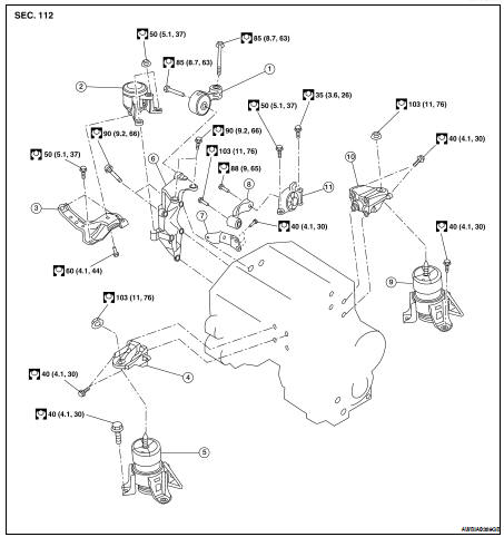
1. Torque rod
2. RH engine mounting insulator
3. RH engine mount support
4. Front engine mounting bracket
5. Front engine mounting insulator
6. RH engine mount bracket
7. Lower torque rod bracket
8. Lower torque rod
9. Rear engine mounting insulator
10. Rear engine mounting bracket
11. Rear lower insulator
WARNING: • Place chocks at front and back of rear wheels.
• For engines not equipped with engine slingers, attach proper slingers and bolts as described in the NISSAN Parts Catalog.
CAUTION: • Do not start working until exhaust system and coolant are cool.
• If items or work required are not covered by the engine main body section, follow the applicable procedures.
• Use the correct supporting points for lifting and jacking. Refer to GI-33, "Garage Jack and Safety Stand".
• In removing the drive shafts, be careful not to damage any transaxle grease seals.
• Before separating the engine and transaxle, remove the crankshaft position sensor (POS).
• Do not damage the edge of the crankshaft position sensor (POS) or the ring gear teeth.
REMOVAL
1. Release fuel pressure. Refer to EC-1579, "Inspection".
2. Drain coolant. Refer to CO-35, "Changing Engine Coolant".
3. Drain power steering fluid. Refer to ST-8, "Draining".
4. Drain transaxle fluid. Refer to TM-17, "Draining" (M/T), TM-241, "Changing" (CVT).
5. Drain clutch fluid (M/T). Refer to CL-7, "Air Bleeding Procedure".
6. Remove hood assembly. Refer to DLK-208, "HOOD ASSEMBLY : Removal and Installation".
7. Remove the engine cover, and the engine under cover using power tool.
8. Remove air intake duct and air cleaner case assembly with mass air flow sensor. Refer to EM-129, "Removal and Installation".
9. Remove battery and tray. Refer to PG-68, "Removal and Installation" (Coupe models) or PG-139, "Removal and Installation" (Sedan models).
10. Remove CVT control unit if equipped.
11. Remove cowl top. Refer to EXT-18, "Removal and Installation".
12. Remove strut bar using power tools. Refer to FSU-12, "Exploded View".
13. Remove IPDM E/R.
14. Remove the following parts: • Evap vacuum hose
• Brake booster vacuum hose
• Heater hoses (engine side)
15. Disconnect the clutch operating cylinder fluid line (M/T only). Refer to CL-12, "Exploded View".
16. Disconnect transaxle shift control cables.
17. Remove upper and lower radiator hoses.
18. Remove power steering reservoir.
19. Disconnect fuel hose quick connection at vehicle piping side. Refer to EM-146, "Removal and Installation".
20. Remove engine mount stay.
21. Remove RH upper engine mount insulator.
22. Remove LH insulator nut.
23. Remove the front drive shafts. Refer to FAX-11, "Removal and Installation (Left Side)" and FAX-12, "Removal and Installation (Right Side)".
24. Remove the front exhaust tube using power tools. Refer to EX-11, "Exploded View".
25. Remove the cooling fan assembly. Refer to CO-40, "Removal and Installation".
26. Discharge and recover the R134a refrigerant. Refer to HA-24, "HFC-134a (R-134a) Service Procedure".
27. Remove the A/C compressor using power tools. Refer to HA-36, "Removal and Installation for Compressor - VQ35DE Models".
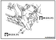
28. Install engine slingers into front of LH cylinder head and rear of RH cylinder head.
• (A): RH cylinder head
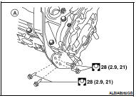
• (B): LH cylinder head
29. Remove rear cover plate.
30. Remove the torque converter bolts (CVT models).
31. Position a suitable support table under suspension member and engine assembly.
32. Disconnect the LH transaxle mount and the RH engine mount.
33. For additional safety, secure the engine in position with suitable tool.
34. Remove suspension member bolts. Refer to FSU-12, "Exploded View".
35. Carefully lower the engine, transaxle assembly and suspension member using Tool, avoiding interference with the vehicle body.
CAUTION: • Before and during this procedure, always check if any harnesses are left connected.
• Avoid any damage to, or any oil/grease smearing or spills onto the engine mounting insulators.
Tool number : KV101J0010 (J-47242)
36. Remove the starter motor. Refer to STR-51, "Removal and Installation".
37. Remove the crankshaft position sensor (POS).
38. Remove engine and transaxle harness.
39. Separate the engine and transaxle and mount the engine on a suitable engine stand.
40. Drain engine oil. LU-24, "Changing Engine Oil"
INSTALLATION
Installation is in the reverse order of removal.
NOTE: Tighten transmission bolts to specification. Refer to TM-26, "Removal and Installation" (M/T), TM-259, "Removal and Installation" (CVT).
INSPECTION AFTER INSTALLATION
• Before starting engine, check the levels of engine coolant, engine oil and working fluid. If less than required quantity, fill to the specified level.
• Use procedure below to check for fuel leakage.
• Turn ignition switch ON (with engine stopped). With fuel pressure applied to fuel piping, check for fuel leakage at connection points.
• Start engine. With engine speed increased, check again for fuel leakage at connection points.
• Run engine to check for unusual noise and vibration.
• Warm up engine thoroughly to make sure there is no leakage of engine coolant, engine oil, working fluid, fuel and exhaust gas.
• Bleed air from passages in pipes and tubes of applicable lines, such as in cooling system.
• After cooling down engine, again check amounts of engine coolant, engine oil and working fluid. Refill to specified level, if necessary.
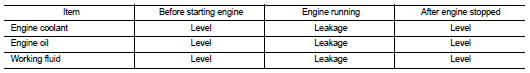
• Summary of the inspection items:

 Cylinder head
 Disassembly and assembly