Nissan Altima (L32) 2007-2012 Service Manual: Disassembly and assembly
FRONT SEAT
DRIVER SIDE
Exploded View
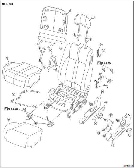
1. Headrest
2. Headrest holder (locked)
3. Headrest holder (free)
4. Seatback board
5. Seatback/frame assembly
6. Inner finisher
7. Seat belt buckle
8. Seat cushion trim
9. Seat harness
10. Seat cushion pad
11. Front leg covers
12. Lumbar lever
13. Power seat outer finisher
14. Seat switch assembly
15. Seat slide switch
16. Power seat recline lever
17. Manual seat lifter finisher
18. Manual seat lifter lever
19. Manual seat recline lever
20. Manual seat outer finisher
21. Manual slide cover
22. Power seat rear leg covers
23. Entry knob
24. Bezel
Disassembly and Assembly
SEAT CUSHION TRIM AND PAD
Disassembly
CAUTION: • During installation, the wire harness clips must be reinstalled in the holes they were originally in. Do not add additional clips. NOTE: If the vehicle has been involved in a collision, the seat must be inspected for damage. Refer to SR-21, "For Side and Rollover Collision".
1. Remove the front seat assembly. Refer to SE-23, "Removal and Installation" 2. Remove the front seat finishers and seat outer finisher.
3. Pull up (A) on the seat cushion trim flap (1).
4. Remove two rear clips retaining the seat cushion trim flap, remove seat cushion assembly.
5. Remove the retainer on the seat cushion frame, then remove the harness connector for the seat heater.
6. After removing the seat cushion trim and pad, remove the hog rings to separate the trim from the pad and seat cushion heater unit.
Assembly
Assembly is in the reverse order of disassembly.
PASSENGER SIDE
Exploded View
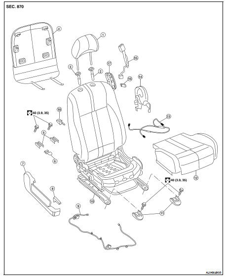
1. Headrest
2. Headrest holder (free)
3. Headrest holder (locked)
4. Seatback board
5. Rear leg covers
6. Clip harness
7. Outer finisher
8. Seatback lever
9. Power seat harness
10. Seatback/frame assembly
11. Front leg covers
12. Seat cushion assembly
13. SRS seat harness
14. Inner finisher
15. Seat belt buckle
16. Release handle
17. Release handle cover
18. Kick lever
Disassembly
Disassembly and Assembly
CAUTION: • During installation, the wire harness clips must be reinstalled in the holes they were originally in. Do not add additional clips.
NOTE: If the vehicle has been involved in a collision, the seat must be inspected for damage. Refer to SR-21, "For Side and Rollover Collision".
1. Remove the front seat assembly. Refer to SE-23, "Removal and Installation" 2. Remove the front seat finishers and seat outer finisher.
3. Pull up (A) on the seat cushion trim flap (1).
4. Remove two rear clips retaining the seat cushion trim flap, remove seat cushion assembly.
5. Remove the retainer on the seat cushion frame, then remove the harness connector for the seat heater.
6. After removing the seat cushion trim and pad, remove the hog rings to separate the trim from the pad and seat cushion heater unit.
Assembly
Assembly is in the reverse order of disasembly.
 Rear seat
 Seat Sedan