Nissan Altima (L32) 2007-2012 Service Manual: Electrical units location
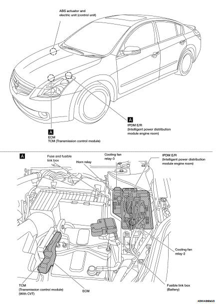
Electrical Units Location
ENGINE COMPARTMENT
PASSENGER COMPARTMENT
LUGGAGE COMPARTMENT
HARNESS CONNECTOR
Description
HARNESS CONNECTOR (TAB-LOCKING TYPE)
• The tab-locking type connectors help prevent accidental looseness or disconnection.
• The tab-locking type connectors are disconnected by pushing or lifting the locking tab(s). Refer to the figure below.
Refer to the next page for description of the slide-locking type connector.
CAUTION: Do not pull the harness or wires when disconnecting the connector.
[Example]
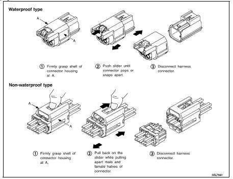
HARNESS CONNECTOR (SLIDE-LOCKING TYPE)
• A new style slide-locking type connector is used on certain systems and components, especially those related to OBD.
• The slide-locking type connectors help prevent incomplete locking and accidental looseness or disconnection.
• The slide-locking type connectors are disconnected by pushing or pulling the slider. Refer to the figure below.
CAUTION: • Do not pull the harness or wires when disconnecting the connector.
• Be careful not to damage the connector support bracket when disconnecting the connector.
[Example]
HARNESS CONNECTOR (LEVER LOCKING TYPE)
• Lever locking type harness connectors are used on certain control units and control modules such as ECM, ABS actuator and electric unit (control unit), etc.
• Lever locking type harness connectors are also used on super multiple junction (SMJ) connectors.
• Always confirm the lever is fully locked in place by moving the lever as far as it will go to ensure full connection.
CAUTION:
• Always confirm the lever is fully released (loosened) before attempting to disconnect or connect these connectors to avoid damage to the connector housing or terminals.
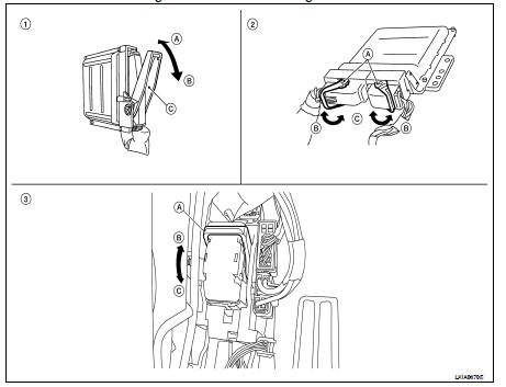
1. Control unit with single lever
A. Fasten
B.Loosen
C.Lever
2. Control unit with dual lever
A. Fasten
B.Loosen
C.Lever
3. SMJ connector
A. Fasten
B.Loosen
C.Lever
HARNESS CONNECTOR (DIRECT-CONNECT SRS COMPONENT TYPE)
• SRS direct-connect type harness connectors are used on certain SRS components such as air bag modules and seat belt pre-tensioners.
• Always pull up to release black locking tab prior to removing connector from SRS components.
• Always push down to lock black locking tab afte4r installing connector to SRS components.n When locked, the black locking tab is level with the connector housing.
CAUTION: • Do not pull the harness or wires when removing connectors from SRS components.
 Ground
 Standardized relay