Nissan Altima (L32) 2007-2012 Service Manual: Front wiper auto stop signal circuit
Component Function Check
1. CHECK FRONT WIPER (AUTO STOP) OPERATION
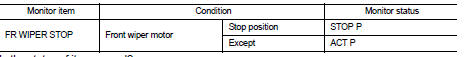
1. Select "FRONT WIPER STOP" of IPDM E/R DATA MONITOR item.
2. Operate the front wiper.
3. With the front wiper operation, check the monitor status.
Is the status of item normal?
YES >> Auto stop signal circuit is normal.
NO >> Refer to WW-24, "Diagnosis Procedure".
Diagnosis Procedure
1. CHECK FRONT WIPER MOTOR (AUTO STOP) OUTPUT VOLTAGE
1. Turn the ignition switch OFF.
2. Disconnect front wiper motor.
3. Turn the ignition switch ON.
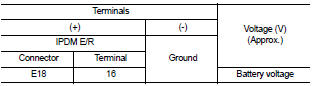
4. Check voltage between IPDM E/R harness connector and
ground.
Is the measurement normal?
YES >> GO TO 2
NO >> Replace IPDM E/R. Refer to PCS-48, "Removal and Installation".
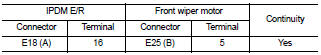
2. CHECK FRONT WIPER MOTOR (AUTO STOP) CIRCUIT CONTINUITY
1. Turn the ignition switch OFF.
2. Disconnect IPDM E/R.
3. Check continuity between IPDM E/R harness connector (A) and
front wiper motor harness connector (B).
Does continuity exist?
YES >> GO TO 3
NO >> Repair or replace harness.
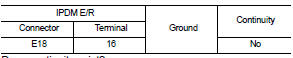
3. CHECK FRONT WIPER MOTOR (AUTO STOP) SHORT CIRCUIT
Check continuity between IPDM E/R harness connector and ground.
Does continuity exist?
YES >> Repair or replace harness.
NO >> Replace front wiper motor. Refer to WW-116, "FRONT
WIPER DRIVE ASSEMBLY : Removal and Installation".
Component Function Check
1. CHECK FRONT WIPER HI OPERATION
1. Start IPDM E/R auto active test. Refer to PCS-14, "Diagnosis Description".
2. Check that the front wiper operates at the ...
Diagnosis Procedure
1.CHECK FRONT WIPER MOTOR (GND) OPEN CIRCUIT
1. Turn the ignition switch OFF.
2. Disconnect front wiper motor.
3. Check continuity between front wiper motor harness connec ...
Other materials: ProPILOT Assist (if so equipped)
WARNING
Failure to follow the warnings and instructions
for proper use of the ProPILOT
Assist system could result in serious
injury or death.
ProPILOT Assist is not a self-driving
system. Within the limits of its capabilities,
as described in this manual, it
helps the driver with certain drivin ...
Bluetooth Hands-Free Phone System
WARNING
Use a phone after stopping your vehicle
in a safe location. If you have to
use a phone while driving, exercise
extreme caution at all times so full
attention may be given to vehicle
operation.
If you are unable to devote full attention
to vehicle operation while talking
on the phon ...
AEB with Pedestrian Detection system
operation
For vehicles with the 7 inch (18 cm) display
Vehicle ahead detection indicator
AEB with Pedestrian Detection emergency
warning indicator
AEB with Pedestrian Detection system
warning light
The AEB system operates at speeds above
approximately 3 mph (5 km/h). For the pedestrian
detection funct ...

 Front wiper motor hi circuit
 Front wiper motor ground circuit