Nissan Altima (L32) 2007-2012 Service Manual: Intake door motor
Description
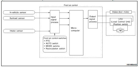
SYSTEM DESCRIPTION
Component Parts
Intake door control system components are: • Front air control
• Intake door motor (LCU)
• In-vehicle sensor
• Ambient sensor
• Sunload sensor
• Intake sensor
System Operation
The intake door control determines intake door position based on the ambient temperature, the intake air temperature and the in-vehicle temperature. When shifting mode position D/F, when the DEF or OFF switches are pressed, or when A/C switch is OFF, the front air. sets the intake door at the FRESH position.
Intake Door Control Specification
COMPONENT DESCRIPTION
Intake Door Motor
The intake door motor (1) is attached to the blower unit. It rotates so that air is drawn from inlets set by the front air control. Motor rotation is conveyed to a lever which activates the intake door.
Diagnosis Procedure
SYMPTOM: • Intake door does not change.
• Intake door motor does not operate normally.
INSPECTION FLOW
1. CONFIRM SYMPTOM BY PERFORMING OPERATION CHECK - REC (
 )
)
1. Press the vent mode.( ).
).
2. Press REC (  ) switch. The REC (
 ) indicator should illumination.
3. Press REC ( ) switch again. The
REC (
) switch again. The
REC (  ) indicator should go out.
4. Listen for intake door position change (you should sound change slightly).
Can a symptom be duplicated? YES >> GO TO 3
NO >> GO TO 2
2. PERFORM COMPLETE OPERATIONAL CHECK
Perform a complete operational check and check for any symptoms. Refer to HAC-5, "Description and Conditions".
Is the inspection result normal? YES >> Refer to HAC-83, "Symptom Matrix Chart".
NO >> System OK.
3. CHECK FOR SERVICE BULLETINS
Check for any service bulletins.
>> GO TO 4
4. CHECK INTAKE DOOR MOTOR OPERATION
Check and verify intake door mechanism for smooth operation.
Is the inspection result normal? YES >> GO TO 5
NO >> Repair as necessary.
5. CHECK LAN SYSTEM CIRCUIT
Perform diagnostic procedure for the LAN system. Refer to HAC-28, "Diagnosis Procedure".
Is the inspection result normal? YES >> GO TO 6
NO >> Repair as necessary.
6. CHECK AMBIENT SENSOR CIRCUIT
Perform diagnostic procedure for the mode door motor. Refer to HAC-32, "Diagnosis Procedure".
Is the inspection result normal? YES >> GO TO 7
NO >> Repair as necessary.
7. CHECK IN-VEHICLE SENSOR CIRCUIT
Perform diagnostic procedure for the in-vehicle sensor circuit. Refer to HAC-53, "Diagnosis Procedure".
Is the inspection result normal? YES >> GO TO 8
NO >> Repair as necessary.
8. CHECK SUNLOAD SENSOR CIRCUIT
Perform diagnostic procedure for the sunload sensor circuit. Refer to HAC-56, "Diagnosis Procedure".
Is the inspection result normal? YES >> GO TO 9
NO >> Repair as necessary.
9. CHECK INTAKE SENSOR CIRCUIT
Perform diagnostic procedure for the intake sensor circuit. Refer to HAC-59, "Diagnosis Procedure".
Is the inspection result normal? YES >> GO TO 10
NO >> Repair as necessary.
10. CHECK AIR MIX DOOR MOTORS PBR CIRCUIT
Perform diagnostic procedure for the intake sensor circuit. Refer to HAC-35, "Diagnosis Procedure".
Is the inspection result normal? YES >> GO TO 11
NO >> Repair as necessary.
11. RECHECK FOR SYMPTOMS
Perform a complete operational check and check for any symptoms. Refer to HAC-5, "Description and Conditions".
Does another symptom exist? YES >> Repair as necessary.
NO >> Replace front air control. Refer to VTL-8, "Removal and Installation".
DIAGNOSIS PROCEDURE FOR INTAKE DOOR MOTOR
SYMPTOM: Intake door motor does not operate normally.
Perform diagnosis procedure. Refer to HAC-28, "Diagnosis Procedure".
 Air mix door motor
 Blower motor