Nissan Altima (L32) 2007-2012 Service Manual: Blower motor
Description
SYSTEM DESCRIPTION
Component Parts
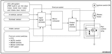
Fan speed control system components are: • Front air control
• A/C LAN system (PBR built-in mode door motor, air mix door motors and intake door motor)
• In-vehicle sensor
• Ambient sensor
• Sunload sensor
• Intake sensor
• Fan control amp.
System Operation
Automatic Mode
In the automatic mode, the blower motor speed is calculated by the front air control based on the input from the PBR, in-vehicle sensor, sunload sensor, intake sensor and ambient sensor.
When the air flow is increased, the duty ratio of the blower fan motor’s drive signal is changed at 8%/sec. to prevent a sudden increase in air flow.
In addition to manual air flow control and the usual automatic air flow control, starting air flow control, low water temperature starting control and high passenger compartment temperature starting control are available.
Starting Fan Speed Control
Start up from COLD SOAK Condition (Automatic mode) In a cold start up condition where the engine coolant temperature is below 56°C (133°F), the blower will not operate for a short period of time (up to 150 seconds). The exact start delay time varies depending on the ambient and engine coolant temperature.
In the most extreme case (very low ambient) the blower starting delay will be 150 seconds as described above. After this delay, the blower will operate at low speed until the engine coolant temperature rises above 56°C (133°F), at which time the blower speed will increase to the objective speed.
Start up from usual or HOT SOAK Condition (Automatic mode)
The blower will begin operation momentarily after the AUTO switch is pressed. The blower speed will gradually rise to the objective speed over a time period of 3 seconds or less (actual time depends on the objective blower speed).
Blower Speed Compensation
Sunload
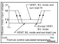
When the in-vehicle temperature and the set temperature are very close, the blower will be operating at low speed. The low speed will vary depending on the sunload. During conditions of low or no sunload, the blower speed is at duty ratio 25%. During high sunload conditions, the front air control. raise the blower speed (duty ratio 49%).
Blower Speed Control Specification
Component Function Check
INSPECTION FLOW
1. CONFIRM SYMPTOM BY PERFORMING OPERATION CHECK - FRONT BLOWER
1. Rotate the blower control dial clockwise. Blower should operate.
2. Rotate the blower control dial clockwise, and continue checking blower speed until all speeds are checked.
Can a symptom be duplicated? YES >> GO TO 3
NO >> GO TO 2
2. PERFORM COMPLETE OPERATIONAL CHECK
Perform a complete operational check and check for any symptoms. Refer to HAC-83, "Symptom Matrix Chart".
Is the inspection result normal? YES >> Refer to HAC-83, "Symptom Matrix Chart".
NO >> System OK.
3. CHECK FOR SERVICE BULLETINS
Check for any service bulletins.
>> GO TO 4
4. CHECK ENGINE COOLANT TEMPERATURE.
Check engine coolant temperature.
Is engine coolant temperature below 56°C (133°F)? YES >> GO TO 5
NO >> Blower motor operation is normal.
5. CHECK BLOWER MOTOR STARTING SPEED.
Check blower motor starting blower speed control.
Is blower motor operation under starting blower speed control? YES >> GO TO 6
NO >> Check blower motor circuit. Refer to HAC-42, "Diagnosis Procedure".
6. CHECK AMBIENT SENSOR CIRCUIT
Perform diagnostic procedure for the mode door motor. Refer toHAC-32, "Diagnosis Procedure".
Is the inspection result normal? YES >> GO TO 7
NO >> Repair as necessary.
7. CHECK IN-VEHICLE SENSOR CIRCUIT
Perform diagnostic procedure for the in-vehicle sensor circuit. Refer to HAC-53, "Diagnosis Procedure".
Is the inspection result normal? YES >> GO TO 8
NO >> Repair as necessary.
8. CHECK SUNLOAD SENSOR CIRCUIT
Perform diagnostic procedure for the sunload sensor circuit. Refer to HAC-56, "Diagnosis Procedure".
Is the inspection result normal? YES >> GO TO 9
NO >> Repair as necessary.
9. CHECK INTAKE SENSOR CIRCUIT
Perform diagnostic procedure for the intake sensor circuit. Refer to HAC-59, "Diagnosis Procedure".
Is the inspection result normal? YES >> GO TO 10
NO >> Repair as necessary.
10. RECHECK FOR SYMPTOMS
Perform a complete operational check and check for any symptoms. Refer to HAC-5, "Description and Conditions".
Does another symptom exist? YES >> Repair as necessary.
NO >> Replace front air control. Refer to VTL-8, "Removal and Installation".
Diagnosis Procedure
SYMPTOM: Blower motor operation is malfunctioning.
DIAGNOSIS PROCEDURE FOR BLOWER MOTOR
SYMPTOM: Blower motor operation is malfunctioning under starting blower speed control.
1.CHECK POWER SUPPLY FOR BLOWER MOTOR
1. Disconnect fuse block (J/B) connector.
2. Press ignition switch ON.
3. Check voltage between fuse block (J/B) harness connector E6 terminal P6 and ground.
Is the inspection result normal? YES >> GO TO 2
NO >> Check power supply circuit and 15A fuses [Nos. 21 and 22, located in the fuse block (J/B)].
• If OK, check for open circuit in wiring harness.
Repair or replace as necessary.
• If OK, check fuses and check wiring harness for possible open or short circuit.
• If OK, GO TO 5
2.CHECK BODY GROUND CIRCUIT FOR BLOWER MOTOR
1. Disconnect blower motor connector.
2. Press ignition switch OFF.
3. Check continuity between blower motor harness connector M31 terminal 1 and ground.
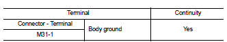
Is the inspection result normal? YES >> Reconnect blower motor harness connector and GO TO 3
NO >> Repair harness or connector.
3.CHECK BLOWER MOTOR CONTROL CIRCUIT BETWEEN BLOWER MOTOR AND FRONT AIR CONTROL
1. Disconnect front air control harness connector.
2. Check continuity between blower motor harness connector M31 (A) terminal 3 and front air control harness connector M37 (B) terminal 1.
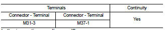
Is the inspection result normal? YES >> GO TO 4
NO >> Repair harness or connector.
4.CHECK POWER SUPPLY FOR FRONT AIR CONTROL
1. Press ignition switch ON.
2. Check voltage between front air control harness connector M37 terminals 39, 19, 40 and ground.
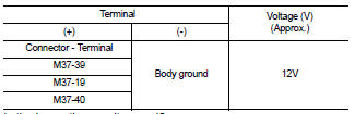
Is the inspection result normal? YES >> 1. Replace front air control. Refer to VTL-8, "Removal and Installation".
2. Confirm that blower motor operation is normal.
NO >> • Check for open circuit in wiring harness.
Repair or replace as necessary.
• If OK, replace fuse and check wiring harness for short circuit.
Repair or replace an necessary.
5.CHECK POWER SUPPLY FOR FRONT BLOWER MOTOR RELAY
1. Connect fuse block (J/B) connector.
2. Press ignition switch ON.
3. Turn blower motor control dial to any speed except OFF.
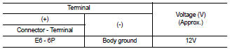
4. Check voltage between fuse block (J/B) E6 terminal 6P and ground.
6P - Ground : Battery Voltage
Is the inspection result normal? YES >> GO TO 9
NO >> GO TO 6
6.CHECK POWER SUPPLY FOR FRONT BLOWER MOTOR RELAY FOR AN OPEN
1. Press ignition switch OFF.
2. Disconnect BCM harness connector M19.
3. Disconnect fuse block (J/B) connector.
4. Check continuity between BCM harness connector M19 (A) terminal 90 and fuse block (J/B) harness connector E6 (B) terminal 6P.
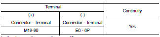
Is the inspection result normal? YES >> GO TO 7
NO >> Repair harness or connector.
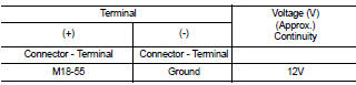
7.CHECK BLOWER FAN SWITCH SIGNAL FOR VOLTAGE
1. Disconnect BCM harness connector M18.
2. Press ignition switch ON.
3. Check voltage between BCM harness connector M18 terminal 55 and ground.
Is the inspection result normal? YES >> Replace BCM. Refer to BCS-96, "Removal and Installation".
NO >> GO TO 8
8.CHECK BLOWER FAN SWITCH SIGNAL CIRCUIT FOR AN OPEN
1. Press ignition switch OFF.
2. Disconnect front air control harness connector.
3. Check continuity between BCM harness connector M18 (A) terminal 55 and front air control harness connector M37 (B) terminal 24.
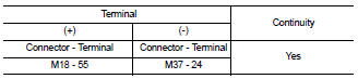
Is the inspection result normal? YES >> Replace front air control. Refer to VTL-8, "Removal and Installation".
NO >> Repair harness or connector.
9.CHECK FRONT BLOWER MOTOR RELAY GROUND
1. Press ignition switch OFF.
2. Disconnect fuse block (J/B) harness connector M5.
3. Check continuity between fuse block (J/B) harness connector M5 terminal 7M and ground.
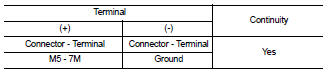
Is the inspection result normal? YES >> Replace front blower motor relay.
NO >> Repair harness or connector.
 Intake door motor
 Magnet clutch