Nissan Altima (L32) 2007-2012 Service Manual: Intake manifold
Removal and Installation
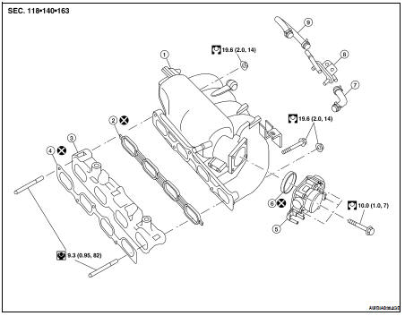
1. Intake manifold
2. Rubber seal
3. Intake manifold adapter
4. Gasket
5. Electric throttle control actuator
6. Rubber seal
7. PCV hose
8. EVAP canister purge volume control solenoid valve
9. EVAP hose
REMOVAL
WARNING: To avoid the danger of being scalded, never drain the coolant when the engine is hot.
1. Release the fuel pressure. Refer to EC-550, "Inspection" (California), EC-1038, "Inspection" (Except California).
2. Drain coolant when engine is cooled. Refer to CO-12, "Changing Engine Coolant".
3. Disconnect the MAF sensor electrical connector.
4. Remove air cleaner and air duct assembly. Refer to EM-25, "Removal and Installation".
5. Remove cowl top finisher. Refer to EXT-18, "Removal and Installation".
6. Disconnect the following components at the intake side: • PCV hose
• EVAP hose and EVAP canister purge volume control solenoid
• Electric throttle control actuator
• Brake booster vacuum hose
7. Disconnect the fuel quick connector on the engine side.
• Using Tool perform the following steps to disconnect the quick connector.
Tool number : 16441 6N210 (J-45488)
a. Remove quick connector cap.
b. With the sleeve side of Tool facing quick connector, install Tool onto fuel tube.
c. Insert Tool into quick connector until sleeve contacts and goes no further. Hold the Tool on that position.

CAUTION: Inserting the Tool hard will not disconnect quick connector.
Hold Tool where it contacts and goes no further.
d. Pull the quick connector straight out from the fuel tube.
CAUTION: • Pull quick connector holding it at the (A) position, as shown.
• Do not pull with lateral force applied. O-ring inside quick connector may be damaged.
• Prepare container and cloth beforehand as fuel will leak out.
• Avoid fire and sparks.
• Be sure to cover openings of disconnected pipes with plug or plastic bag to avoid fuel leakage and entry of foreign materials.
8. When removing fuel hose quick connector at vehicle piping side, perform as follows.
a. Remove quick connector cap.
b. Hold the sides of the connector, push in tabs and pull out the tube. (The figure is shown for reference only.) • If the connector and the tube are stuck together, push and pull several times until they start to move. Then disconnect them by pulling.
CAUTION: • The tube can be removed when the tabs are completely depressed. Do not twist it more than necessary.
• Do not use any tools to remove the quick connector.
• Keep the resin tube away from heat. Be especially careful when welding near the tube.
• Prevent acid liquid such as battery electrolyte etc. from getting on the resin tube.
• Do not bend or twist the tube during installation and removal.
• Do not remove the remaining retainer on tube.
• When the tube is replaced, also replace the retainer with a new one.
Retainer color: Green.
• To keep clean the connecting portion and to avoid damage and foreign materials, cover them completely with plastic bags or something similar.
9. Disconnect electric throttle control actuator coolant hoses.
10. Loosen bolts diagonally, and remove the electric throttle control actuator.
CAUTION: Handle carefully to avoid any damage.
11. Remove the bolts and nuts in the order shown and remove the intake manifold assembly, using power tools.
CAUTION: Cover engine openings to avoid entry of foreign materials.
Inspection After Removal
Surface Distortion
• Using straightedge and feeler gauge, inspect surface distortion of intake manifold adapter and intake manifold surface. Refer to EM-99, "Standard and Limit".
INSTALLATION
Installation is in the reverse order of removal. Follow the tightening sequences below.
Tightening Intake Manifold Bolts and Nuts • Tighten in numerical order as shown.
CAUTION: After tightening the five bolts in the order shown, the 1, 6 position designates that the first bolt tightened is to be retightened to specification.
• Installation of Electric Throttle Control Actuator: - Tighten the bolts of electric throttle control actuator equally and diagonally in several steps.
- After installation perform procedure in "INSPECTION AFTER INSTALLATION".
CONNECTING QUICK CONNECTOR ON THE FUEL HOSE (ENGINE SIDE)
1. Make sure no foreign substances are deposited in and around the fuel tube and quick connector, and there is no damage to them.
2. Thinly apply new engine oil around the fuel tube tip end.
3. Align center to insert quick connector straight into fuel tube.
• Insert fuel tube into quick connector until the top spool on fuel tubes is inserted completely and the second level spool is positioned slightly below the quick connector bottom end.
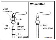
CAUTION: • Hold at position (A) as shown, when inserting the fuel tube into the quick connector.
• Carefully align to center to avoid inclined insertion to prevent damage to the O-ring inside the quick connector.
• Insert the fuel tube until you hear a “click” sound and actually feel the engagement.
• To avoid misidentification of engagement with a similar sound, be sure to perform the next step.
4. Before clamping the fuel hose with the hose clamp, pull the quick connector hard by hand, holding at the (A) position, as shown. Make sure it is completely engaged (connected) so that it does not come off of the fuel tube.
NOTE: Recommended pulling force is 50 N (5.1 kg, 11.2 lb).
5. Install quick connector cap on quick connector joint.
• Direct arrow mark on quick connector cap to upper side (fuel hose side).
6. Install fuel hose to hose clamp.
CONNECTING QUICK CONNECTOR ON THE FUEL HOSE (VEHICLE PIPING SIDE)
1. Make sure no foreign substances are deposited in and around the fuel tube and quick connector, and there is no damage to them.
2. Align center to insert quick connector straight into fuel tube.
• Insert fuel tube until a click is heard.
• Install quick connector cap on quick connector joint. Direct arrow mark on quick connector cap upper side.
• Install fuel hose to hose clamp.
INSPECTION AFTER INSTALLATION
Make sure there is no fuel leakage at connections as follows: 1. Apply fuel pressure to fuel lines by turning ignition switch ON (with engine stopped). Then check for fuel leaks at connections.
2. Start the engine and rev it up and check for fuel leaks at connections.
• Perform procedures for “Throttle Valve Closed Position Learning” after finishing repairs. Refer to EC-29, "THROTTLE VALVE CLOSED POSITION LEARNING : Description" (California), EC-565, "THROTTLE VALVE CLOSED POSITION LEARNING : Description" (Except California).
• If electric throttle control actuator is replaced, perform procedures for “Idle Air Volume Learning” after finishing repairs. Refer to EC-30, "IDLE AIR VOLUME LEARNING : Description" (California), EC-566, "IDLE AIR VOLUME LEARNING : Description" (Except California).
WARNING: Do not touch engine immediately after stopping as engine is extremely hot.
NOTE: Use mirrors for checking on connections out of the direct line of sight.
 Air cleaner and air duct
 Exhaust manifold and three way
catalyst
Exhaust manifold and three way
catalyst