Nissan Altima (L32) 2007-2012 Service Manual: Intelligent key system/engine start function
System Diagram

System Description
INPUT/OUTPUT SIGNAL CHART
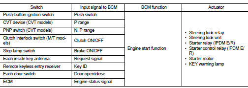
SYSTEM DESCRIPTION
• The engine start function of Intelligent Key system is a system that makes it possible to start and stop the engine without removing the key. It verifies the electronic ID using two-way communications when pressing the push-button ignition switch while carrying the Intelligent Key, which operates based on the results of electronic ID verification for Intelligent Key using two-way communications between the Intelligent Key and the vehicle.
NOTE: The driver should carry the Intelligent Key at all times.
• Intelligent Key has 2 IDs [for Intelligent Key and for NVIS (NATS)]. It can perform the door lock/unlock operation and the push-button ignition switch operation when the registered Intelligent Key is carried.
• When the Intelligent Key battery is discharged, it can be used as emergency back-up by inserting the Intelligent Key to the key slot. At that time, perform the NVIS (NATS) ID verification. If it is used when the Intelligent Key is carried, perform the Intelligent Key ID verification.
• If the ID is successfully verified, and when push-button ignition switch is pressed, steering lock will be released and initiating the engine will be possible.
• If the door lock/unlock operation is performed when the Intelligent Key battery is discharged, all doors lock/ unlock can be performed by operating the driver door key cylinder using the mechanical key set in the Intelligent Key.
• Intelligent Key can be registered up to 4 keys (Including the standard Intelligent Key) on request from the owner.
NOTE: • Refer to DLK-246, "INTELLIGENT KEY : System Description" for any functions other than engine start function of Intelligent Key system.
PRECAUTIONS FOR INTELLIGENT KEY SYSTEM
• In the Intelligent Key system of model L32, the transponder [the chip for NVIS (NATS) ID verification] is integrated into the Intelligent Key. (For the conventional models, it is integrated into the mechanical key.) Therefore, the mechanical key cannot perform the ID verification, and thus it cannot start the engine. Instead, the NVIS (NATS) ID verification can be performed by inserting the Intelligent Key into the key slot, and then it can start the engine.
OPERATION WHEN INTELLIGENT KEY IS CARRIED
1. When the push-button ignition switch is pressed and brake pedal is depressed, the BCM signals the inside key antenna and transmits the request signal to the Intelligent Key.
2. The Intelligent Key sends the request signal and transmits the Intelligent Key ID signal to the BCM via the remote keyless entry receiver.
3. The BCM receives the Intelligent Key ID signal and verifies it with the registered ID.
4. BCM transmits the steering lock unlock signal to steering lock unit and IPDM E/R if the verification results are OK.
5. IPDM E/R turns the steering lock relay ON and supplies power to the steering lock unit.
6. Release of the steering lock.
7. BCM transmits the power supply stop signal to IPDM E/R when it confirms that the steering lock is in the unlock condition.
8. IPDM E/R turns the steering lock relay OFF and stops power supply to the steering lock unit.
9. BCM turns ACC relay ON and transmits the ignition power supply ON signal to IPDM E/R.
10. IPDM E/R turns the ignition relay ON and starts the ignition power supply.
11. BCM confirms that the shift position is P or N (CVT models).
12. BCM transmits the starter request signal via CAN communication to IPDM E/R and turns the starter relay in IPDM E/R ON if BCM judges that the engine start condition is satisfied.
13. IPDM E/R turns the starter control relay ON when receiving the starter request signal.
14. Battery power is supplied through the starter relay and the starter control relay to operate the starter motor and to start the cranking.
CAUTION: If a malfunction is detected in the Intelligent Key system, the “KEY” warning lamp in the combination meter illuminates. At that time, the engine cannot be started. 15. When BCM received feedback signal from ECM acknowledging the engine has been initiated, the BCM transmits a stop signal to IPDM E/R and stops the cranking by turning OFF the starter motor relay. (If the engine initiating has failed, the cranking will stop automatically within 5 seconds.) CAUTION: When the Intelligent Key is carried outside of the vehicle (inside key antenna detection area) with the power supply in ACC or ON position, even if the engine start condition* is satisfied, the engine cannot be started. *: For the engine start condition, refer to “PUSH-BUTTON IGNITION SWITCH OPERATION PROCEDURE”.
OPERATION RANGE
Engine can be started when Intelligent Key is inside the vehicle. However, sometimes engine might not start when Intelligent Key is on instrument panel or in glove box.
OPERATION WHEN KEY SLOT IS USED
When the Intelligent Key battery is discharged, it performs the NVIS (NATS) ID verification between the integrated transponder and BCM by inserting the Intelligent Key into the key slot, and then the engine can be started.
For details relating to starting the engine using key slot, refer to SEC-215, "System Description".
BATTERY SAVER SYSTEM
When all the following conditions are met for 60 minutes, the battery saver system will cut off the power supply to prevent battery discharge.
• The ignition switch is in the ACC position
• All doors are closed
• CVT selector lever is in the P position
• No Intelligent Key failures (Intelligent Key warning indicator is not ON)
Reset Condition of Battery Saver System
CVT models
In order to prevent the battery from discharging, the battery saver system will cut off the power supply when all doors are closed, the selector lever is on P position and the ignition switch is left on ACC position for 1 hour. If any of the following conditions are met the battery saver system is released and the steering will change automatically to lock position from OFF position.
• Opening any door
• Operating with request switch on door lock
• Operating with Intelligent Key on door lock
Press push-button ignition switch and ignition switch will change to ACC position from OFF position.
M/T models
If any of the conditions above is met the battery saver system is released but the steering will not lock.
In this case, the steering operation OFF to LOCK is prohibited.
STEERING LOCK OPERATION
Steering is locked by steering lock unit when ignition switch is in the OFF position, CVT selector lever is in the P position and any of the following conditions are met.
• Opening door
• Closing door
• Door is locked with request switch
• Door is locked with Intelligent Key
PUSH-BUTTON IGNITION SWITCH OPERATION PROCEDURE
The power supply position changing operation can be performed with the following operations.
NOTE: • When an Intelligent Key is within the detection area of inside key antenna or when it is inserted to the key slot, it is equivalent to the operations below.
• When starting the engine, the BCM monitors under the engine start conditions, - Brake pedal operating condition (CVT models) - CVT selector lever position (CVT models) - Clutch pedal operating condition (M/T models) - Vehicle speed
- Steering lock condition
- Engine status
• Unless each start condition is fulfilled, the engine will not respond regardless of how many times the engine switch is pressed. At that time, illumination repeats the position in the order of LOCK→ACC→ON→OFF.
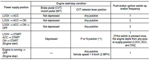
*1: When the CVT selector lever position is N position, the engine start condition is different according to the vehicle speed.
• At vehicle speed of 4 km/h (2 MPH) or less, the engine can start only when the brake pedal is depressed.
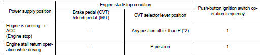
• At vehicle speed of 4 km/h (2 MPH) or more, the engine can start even if the brake pedal is not depressed. (It is the same as “Engine stall return operation while driving”.) *2: When the CVT selector lever position is in any position other than P position and when the vehicle speed is 5 km/h (3 MPH) or more, the engine stop condition is different.
• Press and hold the push-button ignition switch for 2 seconds or more. (When the push-button ignition switch is pressed for too short a time, the operation may be invalid, so properly press and hold to prevent an incorrect operation.) • Press the push-button ignition switch 3 times or more within 1.5 seconds. (Emergency stop operation)
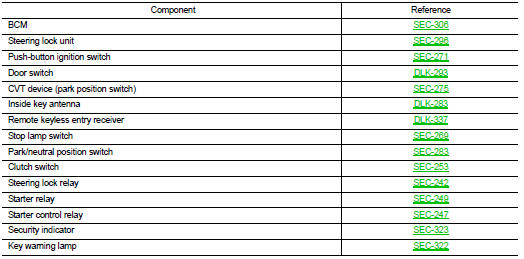
Component Parts Location
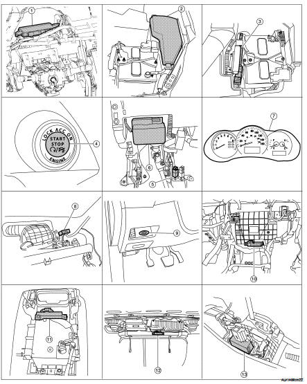
1. Body control module (view with instrument panel removed)
2. IPDM E/R
3. ECM
4. Push button ignition switch
5. Stop lamp switch (view with lower driver instrument panel removed)
6. Steering lock unit (steering column)
7. Combination meter
8. Remote keyless entry receiver (view with instrument panel removed)
9. Key slot
10. Instrument panel antenna (view with instrument panel removed)
11. Front console antenna (bottom view of console)
12. Rear parcel shelf antenna
13. CVT device (park position switch)
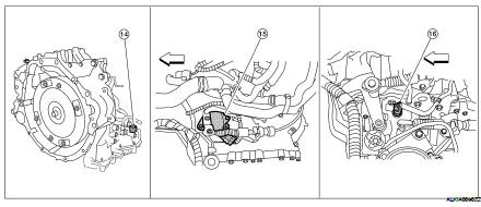
14. Park neutral position switch connector (switch inside trans) (CVT/VQ)
15. Park neutral position switch (CVT/ QR)
16. Park neutral position switch (M/T)
Component Description
 Function diagnosis
 NVIS (Nissan vehicle immobilizer system-nats)