Nissan Altima (L32) 2007-2012 Service Manual: IPDM-E branch line circuit
Diagnosis Procedure
INSPECTION PROCEDURE
1.CHECK CONNECTOR
1. Turn the ignition switch OFF.
2. Disconnect the battery cable from the negative terminal.
3. Check the terminals and connectors of the IPDM E/R for damage, bend and loose
connection (unit side
and connector side).
Is the inspection result normal?
YES >> GO TO 2.
NO >> Repair the terminal and connector.
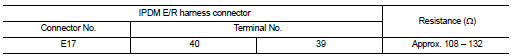
2.CHECK HARNESS FOR OPEN CIRCUIT
1. Disconnect the connector of IPDM E/R.
2. Check the resistance between the IPDM E/R harness connector terminals.
Is the measurement value within the specification?
YES >> GO TO 3.
NO >> Repair the IPDM E/R branch line.
3.CHECK POWER SUPPLY AND GROUND CIRCUIT
Check the power supply and the ground circuit of the IPDM E/R. Refer to
PCS-23, "Diagnosis Procedure" .
Is the inspection result normal?
YES (Present error)>>Replace the IPDM E/R. Refer to PCS-48, "Removal and
Installation".
YES (Past error)>>Error was detected in the IPDM E/R branch line.
NO >> Repair the power supply and the ground circuit.
Diagnosis Procedure
INSPECTION PROCEDURE
1.CHECK CONNECTOR
1. Turn the ignition switch OFF.
2. Disconnect the battery cable from the negative terminal.
3. Check the following terminals and c ...
Diagnosis Procedure
INSPECTION PROCEDURE
1.CONNECTOR INSPECTION
1. Turn the ignition switch OFF.
2. Disconnect the battery cable from the negative terminal.
3. Disconnect all the unit connect ...
Other materials: Precautions on child restraints
WARNING
Failure to follow the warnings and instructions
for proper use and installation
of child restraints could result in serious
injury or death of a child or other
passengers in a sudden stop or collision:
The child restraint must be used
and installed properly. Always follow
all of ...
LED Daytime Running Lights (DRL)
system
The LED DRL automatically illuminate at
100% intensity when the engine is started
and the parking brake released. The LED
Daytime Running Lights (DRL) operate with
the headlight switch in any position. When
you turn the headlight switch to the
position for full illumination, the LED DRL
illuminate ...
Headlight control switch
Type A (if so equipped)
Lighting
Rotate the switch to the
position,
and the front parking, tail, license plate,
and instrument panel lights will come
on. The will illuminate in the
meter.
Rotate the switch to the
position,
and the headlights will come on and all
the other lights re ...
 TCM branch line circuit
 Can communication circuit