Nissan Altima (L32) 2007-2012 Service Manual: Magnet clutch
Description
SYSTEM DESCRIPTION
Front air control controls A/C compressor operation by ambient temperature and signal from ECM.
Low Temperature Protection Control Front air control will turn the A/C compressor ON or OFF as determined by a signal detected by ambient sensor.
When ambient temperature is greater than -2°C (28°F), the A/C compressor turns ON. The A/C compressor turns OFF when ambient temperature is less than -5°C (23°F).
Component Function Check
INSPECTION FLOW
1. CONFIRM SYMPTOM BY PERFORMING OPERATION CHECK - MAGNET CLUTCH
1. Press ignition switch ON.
2. Press vent switch (  ).
).
3. Press A/C switch.
4. Confirm that the A/C compressor clutch engages (sound or visual inspection). (Discharge air and blower speed will depend on ambient, in-vehicle and set temperatures).
Can a symptom be duplicated? YES >> GO TO 3
NO >> GO TO 2
2. PERFORM COMPLETE OPERATIONAL CHECK
Perform a complete operational check and check for any symptoms. Refer to HAC-5, "Description and Conditions".
Is the inspection result normal? YES >> Refer to HAC-83, "Symptom Matrix Chart".
NO >> System OK.
3. CHECK FOR SERVICE BULLETINS
Check for any service bulletins.
>> GO TO 4
4. CHECK MAGNET CLUTCH MECHANISM
Check for magnet clutch operation.
Does the magnet clutch engage? YES >> GO TO 5
NO >> Check magnet clutch circuit. Refer to HAC-47, "Diagnosis Procedure".
5. CHECK AMBIENT SENSOR CIRCUIT
Perform diagnostic procedure for the mode door motor. Refer to HAC-32, "Diagnosis Procedure".
Is the inspection result normal? YES >> GO TO 6
NO >> Repair as necessary.
6. CHECK IN-VEHICLE SENSOR CIRCUIT
Perform diagnostic procedure for the in-vehicle sensor circuit. Refer to HAC-53, "Diagnosis Procedure".
Is the inspection result normal? YES >> GO TO 7
NO >> Repair as necessary.
7. CHECK SUNLOAD SENSOR CIRCUIT
Perform diagnostic procedure for the sunload sensor circuit. Refer to HAC-56, "Diagnosis Procedure".
Is the inspection result normal? YES >> GO TO 8
NO >> Repair as necessary.
8. CHECK INTAKE SENSOR CIRCUIT
Perform diagnostic procedure for the intake sensor circuit. Refer to HAC-59, "Diagnosis Procedure".
Is the inspection result normal? YES >> GO TO 9
NO >> Repair as necessary.
9. CHECK AIR MIX DOOR MOTOR PBR CIRCUITS
Perform diagnostic procedure for the air mix door motor circuit. Refer to HAC-35, "Diagnosis Procedure".
Is the inspection result normal? YES >> GO TO 10
NO >> Repair as necessary.
10. RECHECK FOR SYMPTOMS
Perform a complete operational check and check for any symptoms. Refer to HAC-5, "Description and Conditions".
Does another symptom exist? YES >> Repair as necessary.
NO >> Replace front air control. Refer to VTL-8, "Removal and Installation".
Diagnosis Procedure
DIAGNOSIS PROCEDURE FOR MAGNET CLUTCH
SYMPTOM: Magnet clutch does not engage when A/C switch is ON.
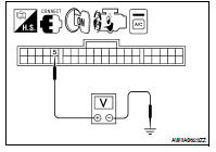
1.CHECK POWER SUPPLY FOR A/C COMPRESSOR
1. Disconnect A/C compressor connector.
2. Start engine and press A/C switch.
3. Check voltage between A/C compressor harness connector F3 terminal 1 and ground.
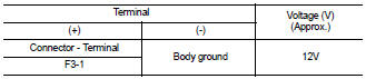
Is the inspection result normal? YES >> Check magnet clutch coil.
1. If NG, replace magnet clutch. Refer to HA-35, "Removal and Installation for Compressor - QR25DE Models" or HA-36, "Removal and Installation for Compressor - VQ35DE Models".
2. If OK, check A/C compressor mounting points for looseness or corrosion and repair as necessary.
NO >> GO TO 2
2.CHECK CIRCUIT CONTINUITY BETWEEN A/C RELAY IN IPDM E/R AND A/C COMPRESSOR
1. Disconnect IPDM E/R connector F10 and A/C compressor connector F3.
2. Check continuity between A/C compressor harness connector F3 (A) terminal 1 and IPDM E/R harness connector F10 (B) terminal 48.
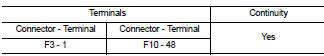
If OK, check harness for short to ground.
Is the inspection result normal? YES >> GO TO 3
NO >> Repair harness or connector.
3.CHECK FUSE IN IPDM E/R
Check 10A fuse (No. 41 located in the IPDM E/R).
Is the inspection result normal? YES >> GO TO 4
NO >> Replace fuse and check IPDM E/R for short circuit. Replace if necessary.
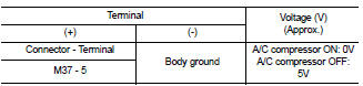
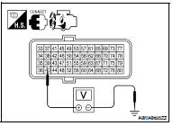
4.CHECK A/C COMPRESSOR ON SIGNAL
Check voltage between front air control connector M37 terminal 5 and ground, with A/C compressor ON and with A/C compressor OFF.
Is the inspection result normal? YES >> GO TO 5
NO >> • When A/C compressor is ON and voltage is not approx. 0V, Replace front air control. Refer to VTL-8, "Removal and Installation".
• When A/C compressor is OFF and voltage is not approx. 5V, BCM is malfunctioning.
5.CHECK CONTINUITY BETWEEN BCM AND FRONT AIR CONTROL
1. Disconnect BCM connector M18 and front air control connector.
2. Check continuity between BCM harness connector M18 (A) terminal 33 and front air control connector M37 (B) terminal 5.
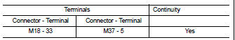
Is the inspection result normal? YES >> GO TO 6
NO >> Repair harness or connector.
6.CHECK REFRIGERANT PRESSURE SENSOR INPUT SIGNAL
1. Reconnect all disconnected connectors.
2. Start the engine.
3. Check voltage between ECM harness connector F13 terminal 39 and ground.
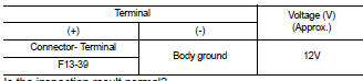
Is the inspection result normal? YES >> GO TO 7
NO >> 1. Repair harness or connector.
2. Confirm that magnet clutch operation is normal.
7.CHECK REFRIGERANT PRESSURE SENSOR
Refer toEC-975, "Diagnosis Procedure" (QR25DE) or EC-1503, "Diagnosis Procedure"(VQ35DE).
Is the inspection result normal? YES >> GO TO 8
NO >> Replace refrigerant pressure sensor. Refer to HA-44, "Removal and Installation for Refrigerant Pressure Sensor".
8.CHECK CAN COMMUNICATION CIRCUITS
Check CAN communication circuits between BCM to ECM and between ECM to IPDM E/R. Refer to LAN-13, "CAN Diagnosis with CONSULT-III".
Is the inspection result normal? YES >> ECM malfunctioning.
NO >> Repair or replace component based on the result of diagnosis.
 Blower motor
 Ambient sensor