Nissan Altima (L32) 2007-2012 Service Manual ≻ Lan system can ≻ Component diagnosis ≻ Malfunction area chart
Nissan Altima (L32) 2007-2012 Service Manual: Malfunction area chart
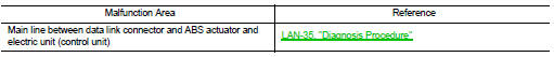
Main Line
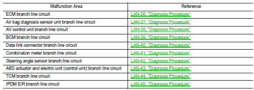
Branch Line
Short Circuit

Main Line
Branch Line
Short Circuit
 Can communication system
 Main line between dlc and abs circuit