Nissan Altima (L32) 2007-2012 Service Manual: Oil pan and oil strainer
Removal and Installation

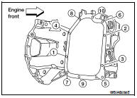
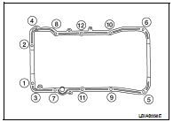
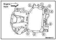
1. Oil pan baffle
2. O-ring
3. Gasket
4. Oil pressure switch
5. Oil cooler gasket
6. Oil cooler
7. Oil cooler connection
8. Oil filter
9. Lower oil pan
10. Oil strainer
11. Rear plate cover
12. Upper oil pan
REMOVAL
WARNING: • You should not remove the oil pan until the exhaust system and cooling system have completely cooled off.
• When removing the front and rear engine through bolts and nuts, lift the engine up slightly for safety.
For engine slingers, refer to EM-202, "Removal and Installation".
CAUTION: When removing the upper oil pan from the engine, first remove the crankshaft position sensor (POS).
Be careful not to damage sensor edges or signal plate teeth.
1. Remove the front RH wheel and tire using power tool. Refer to WT-66.
2. Disconnect the battery negative terminal. Refer to PG-68, "Removal and Installation" (Coupe models) or PG-139, "Removal and Installation" (Sedan models).
3. Remove the oil dipstick.
4. Drain the engine coolant. Refer to CO-35, "Changing Engine Coolant".
5. Remove the engine undercover.
6. Remove the RH inner fender splash shield.
7. Remove the drive belt. Refer to EM-121, "Removal and Installation".
8. Remove the front exhaust tube. Refer to EX-11, "Exploded View".
9. Remove coolant pipe bolts.
10. Remove the A/C compressor with piping attached, and position it out of the way securely with wire.
CAUTION: Do not pull on or crimp the A/C lines and hoses.
11. Disconnect the coolant lines from the engine oil cooler and plug them to prevent coolant loss.
12. Remove the oil filter and engine oil cooler from the upper oil pan.
13. Remove the oil pressure switch, and the crankshaft position sensor (POS) from the upper oil pan.
14. Remove the front drive shaft (RH). Refer to FAX-12, "Removal and Installation (Right Side)".
15. Disconnect the heated oxygen sensors and air flow ratio (A/F) sensors and remove the two catalytic convertors from the exhaust manifolds using power tool. Refer to EM-136, "Removal and Installation".
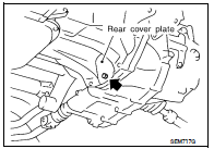
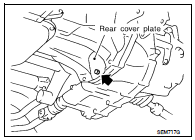
16. Remove the rear plate cover from the upper oil pan.
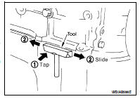
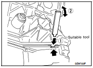
17. Loosen the lower oil pan bolts using power tool in order as shown. Remove the lower oil pan.
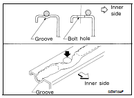
a. Insert Tool between the lower oil pan and the upper oil pan.
Tool number : KV10111100 (J37228)
• Be careful not to damage the mating surface.
• Do not insert a screwdriver, this will damage the mating surfaces.
b. Slide (2) the Tool by tapping (1) its side with a hammer to remove the lower oil pan from the upper oil pan.
18. Remove the four upper oil pan to transaxle bolts.
19. Remove the upper oil pan.
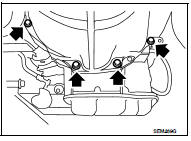
a. Loosen the bolts in the order as shown, using power tool.
b. Insert an appropriate size tool into the notch (1) of the upper oil pan as shown.
c. Pry off the upper oil pan by moving the tool up and down (2) as shown.
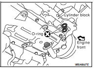
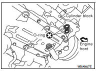
20. Remove the O-ring seals from the bottom of the cylinder block and oil pump housing, use new O-rings for installation.
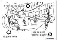
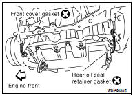
21. Remove front cover gasket and rear oil seal retainer gasket.
22. Remove the oil strainer.
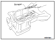
23. If re-installing the original oil pan, remove the old sealant from the mating surfaces using a scraper.
• Also remove the old sealant from mating surface of the cylinder block.
• Remove the old sealant from the bolt holes and threads.
CAUTION: Do not scratch or damage the mating surfaces when cleaning off the old sealant.
INSPECTION AFTER REMOVAL
Clean oil strainer if any object is attached.
INSTALLATION
CAUTION: Wait at least 30 minutes before refilling the engine with oil.
1. Install oil strainer and tighten bolt to specified torque. Refer to EM-139, "Removal and Installation".
2. Apply Genuine Silicone RTV Sealant or equivalent, to the front cover gasket and the rear oil seal retainer gasket as shown.
Refer to GI-15, "Recommended Chemical Products and Sealants".
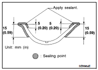
3. Install the front cover gasket and rear oil seal retainer gasket as shown.
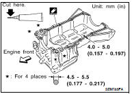
4. Apply a bead of sealant to the cylinder block mating surface of the upper oil pan to a limited portion as shown.
• Use Genuine Silicone RTV Sealant, or equivalent. Refer to GI- 15, "Recommended Chemical Products and Sealants".
• Be sure the sealant is applied to a limited portion as shown, and the sealant is 4.0 - 5.0 mm (0.157 - 0.197 in) or 4.5 - 5.5 mm (0.177 - 0.217 in) wide.
• Attaching should be done within 5 minutes after coating.
5. Install new O-rings on the cylinder block and oil pump body.
6. Install the upper oil pan.
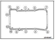
• Tighten upper oil pan bolts in the order as shown.
• Wait at least 30 minutes before refilling the engine with oil.
7. Install the four upper oil pan to transaxle bolts.
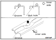
8. Apply a continuous bead of sealant to the lower oil pan.
• Use Genuine Silicone RTV Sealant, or equivalent. Refer to GI- 15, "Recommended Chemical Products and Sealants".
• Be sure the sealant is 4.5 - 5.5 mm (0.177 - 0.217 in) wide.
• Installation must be done within 5 minutes after applying sealant.
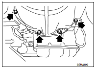
9. Install the lower oil pan. Tighten the lower oil pan bolts in order as shown.
• Wait at least 30 minutes before refilling the engine with oil.
10. Install rear plate cover.
11. Installation of the remaining components is in the reverse order of removal.
INSPECTION AFTER INSTALLATION
• Start the engine and check for leaks. Refer to LU-24, "Changing Engine Oil".
• Inspect the engine oil level. Refer to LU-24, "Changing Engine Oil".
 Exhaust manifold and three way
catalyst
Exhaust manifold and three way
catalyst Ignition coil