Nissan Altima (L32) 2007-2012 Service Manual: Exhaust manifold and three way catalyst
Removal and Installation
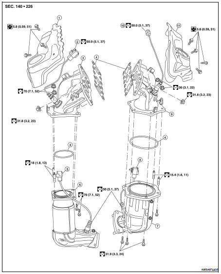
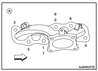
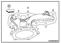
1. Exhaust manifold heat shield (RH)
2. Air fuel ratio (A/F) sensor 1 (bank 1)
3. Exhaust manifold (RH)
4. Gaskets
5. Heated oxygen sensor 2 (bank 1)
6. Three way catalyst (manifold) (bank 1)
7. Three way catalyst (manifold) (bank 2)
8. Heated oxygen sensor 2 (bank 2)
9. Exhaust manifold (LH)
10. Air fuel ratio (A/F) sensor 1 (bank 2)
11. Exhaust manifold heat shield (LH)
REMOVAL
WARNING:
• Perform the work when the exhaust and cooling system have completely cooled down.
• When removing the front and rear engine mounting through bolts and nuts, lift the engine up slightly for safety. For engine slingers, refer to EM-202, "Removal and Installation".
1. Remove the engine and transaxle assembly. Refer to EM-202, "Removal and Installation".
2. Remove the RH and LH three way catalyst supports.
3. Remove heated oxygen sensor 2 (bank 1), heated oxygen sensor 2 (bank 2), air fuel ratio (A/F) sensor 1 (bank 1) and air fuel ratio (A/F) sensor 1 (bank 2).
a. Remove harness connector of each sensor, and disconnect the harness from the bracket and middle clamp.
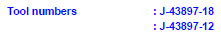
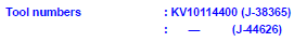
b. Remove both heated oxygen sensors and air fuel ratio (A/F) sensors using Tool.
CAUTION: • Be careful not to damage heated oxygen sensors or air fuel ratio (A/F) sensors.
• Discard any heated oxygen sensor which has been dropped from a height of more than 0.5 m (19.7 in) onto a hard surface such as a concrete floor; replace with a new sensor.
4. Remove exhaust manifold and three way catalyst heat shields with power tool.
5. Remove the three way catalyst (manifold) (bank 1) and three way catalyst (manifold) (bank 2) by loosening the bolts first and then removing the nuts and through bolts.
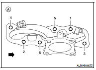
6. Remove the exhaust manifolds RH (A) and LH (B). Loosen the exhaust manifold nuts in the order as shown.

INSPECTION AFTER REMOVAL
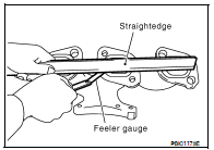
Surface Distortion
• Use a reliable straightedge and feeler gauge to check the flatness of the exhaust manifold mating surfaces.
Limit : 0.3mm (0.012 in)
INSTALLATION
Installation is in the reverse order of removal.
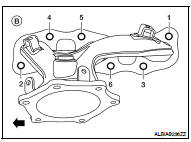
• Install the exhaust manifold nuts in the order as shown RH (A) and LH (B).

CAUTION: • Before installing a heated oxygen sensor or air fuel ratio (A/F) sensor, clean the exhaust manifold threads using the oxygen sensor thread cleaner tool, and apply anti-seize lubricant.
• Do not over-tighten the air fuel ratio (A/F) sensor or heated oxygen sensors. Doing so may cause damage.
 Intake manifold
 Oil pan and oil strainer