Nissan Altima (L32) 2007-2012 Service Manual: On-vehicle maintenance
REAR SUSPENSION ASSEMBLY
On-vehicle Service
• Check the suspension parts for excessive play, cracks, wear or damage. Shake each rear wheel to check for excessive play.
• Retighten all nuts and bolts to the specified torque.
• Make sure that the cotter pin is installed.
• Check the shock absorber for oil leakage or other damage.
• Check the wheelarch height. Refer to RSU-19, "Wheelarch Height (Unladen*1)".
• Check the suspension ball joint for grease leakage and the ball joint dust cover for cracks or other damage.
Inspection
SHOCK ABSORBER ASSEMBLY
• Check for smooth operation through a full stroke for both compression and extension.
• Check for oil leakage on the welded or gland packing portions.
• Check the shock absorber piston rod for cracks, deformation, or other damage and replace if necessary.
SUSPENSION ARM
• Check the suspension arm for damage, cracks, deformation and replace if necessary.
• Check the rubber bushings for damage, cracks and deformation. Replace suspension arm if necessary.
• Check the ball joint. Replace the suspension arm assembly if any of the following conditions exist: - Ball stud is worn.
- Joint is hard to swing.
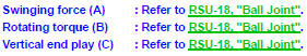
- Check if the swinging force (A), rotating torque (B), or vertical end play (C) is out of specification using Tool.
Tool number : ST3127S000 (J-25765-A)
NOTE: Before checking specifications, turn the ball joint at least 10 revolutions so the ball joint is properly broken in.
RADIUS ROD
• Check the radius rod for any deformation, cracks, or damage and replace if necessary.
• After installing the radius rod, check the wheel alignment and adjust if necessary. Refer to RSU-18, "Rear Wheel Alignment (Unladen*)".
FRONT LOWER LINK
• Check the front lower link for any deformation, cracks, or damage and replace if necessary.
UPPER AND LOWER RUBBER SEATS
• Check the upper and lower rubber seats for deterioration, or cracks and replace if necessary.
REAR LOWER LINK AND COIL SPRING
• Check the rear lower link and coil spring for any deformation, cracks, or other damage and replace if necessary.
STABILIZER BAR
• Check the stabilizer bar and clamps for any deformation, cracks, or damage and replace if necessary.
• Check the rubber bushings for deterioration, or cracks and replace if necessary.
Inspection and Adjustment
Before checking the rear wheel alignment, make a preliminary inspection.
• Measure the wheel alignment under unladen conditions.
NOTE: Unladen conditions mean that fuel, engine coolant, and lubricants are full. That the spare tire, jack, hand tools, and mats are in their designated positions.
PRELIMINARY INSPECTION
• Check the tires for wear and for improper inflation.
• Check the wheels for deformation, cracks, and other damage. Remove the wheel and check the wheel runout. Refer to WT-64, "Inspection".
• Check the rear wheel bearings for looseness.
• Check the rear suspension for looseness.
• Check that the rear shock absorbers work properly.
• Check the wheelarch height in the unladen condition. Refer to RSU-19, "Wheelarch Height (Unladen*1)".
GENERAL INFORMATION AND RECOMMENDATIONS
1. A Four-Wheel Thrust Alignment should be performed.
• This type of alignment is recommended for any NISSAN vehicle.
• The four-wheel “thrust” process helps ensure that the vehicle is properly aligned and the steering wheel is centered.
• The alignment machine itself should be capable of accepting any NISSAN vehicle.
• The alignment machine should be checked to ensure that it is level.
2. Make sure the alignment machine is properly calibrated.
• Your alignment machine should be regularly calibrated in order to give correct information.
• Check with the manufacturer of your specific alignment machine for their recommended Service/Calibration Schedule.
THE ALIGNMENT PROCESS
IMPORTANT: Use only the alignment specifications listed in this Service Manual. Refer to RSU-19, "Wheelarch Height (Unladen*1)".
1. When displaying the alignment settings, many alignment machines use “indicators”: (Green/red, plus or minus, Go/No Go). Do NOT use these indicators.
• The alignment specifications programmed into your alignment machine that operate these indicators may not be correct.
• This may result in an ERROR.
2. Some newer alignment machines are equipped with an optional “Rolling Compensation” method to “compensate” the sensors (alignment targets or head units). Do NOT use this “Rolling Compensation” method.
• Use the “Jacking Compensation” method. After installing the alignment targets or head units, raise the vehicle and rotate the wheels 1/2 turn both ways.
• See Instructions in the alignment machine you are using for more information.
CAMBER
• Measure the camber of both the right and left wheels using a suitable alignment gauge and adjust using the following procedure.

• If the camber is not within specification, adjust the camber by turning the adjusting bolts in the same direction.
1. Turn the adjusting bolts in the same direction to calibrate.
NOTE: Camber changes about 5° with each graduation of the adjusting bolt.
2. Tighten the adjusting bolt nuts to the specified torque.
Adjusting bolt nuts : Refer to RSU-10, "Exploded View".
TOE-IN
Measure the toe-in using the following procedure. If out of specification, inspect and replace any damaged or worn rear suspension parts before adjusting.
WARNING: • Always perform the following procedure on a flat surface.
• Make sure that no person is in front of the vehicle before pushing it.
1. Bounce rear of vehicle up and down to stabilize the posture.
2. Push the vehicle straight ahead about 5 m (16 ft).
3. Put a mark on base line of the tread (rear side) of both tires at the same height of hub center. This mark is a measuring point.
4. Measure distance (A) from rear side.
5. Push the vehicle slowly ahead to rotate the wheels 180° degrees (1/2 a turn).
• If the wheels have rotated more than 180° degrees (1/2 a turn), try the above procedure again from the beginning. Never push vehicle backward.
6. Measure distance (B) from front side.
Total toe-in : Refer to RSU-18, "Rear Wheel Alignment (Unladen*)".
7. Adjust toe-in by turning adjusting bolts.
NOTE: Toe changes about 1.5 mm (0.059 in) [One side] with each graduation of the adjusting bolt.
8. Tighten the adjusting bolt nuts to the specified torque.
Adjusting bolt nuts : Refer to RSU-10, "Exploded View".
 Preparation
 Removal and installation