Nissan Altima (L32) 2007-2012 Service Manual: Removal and installation
REAR SUSPENSION ASSEMBL
Exploded View
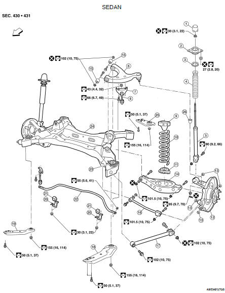
1. Cap
2. Shock absorber insulator
3. Shock absorber seal
4. Bound bumper
5. Shock absorber
6. Suspension arm
7. Connecting rod mount bracket
8. Connecting rod
9. Upper rubber seat
10. Coil spring
11. Lower rubber seat
12. Knuckle
13. Knuckle bushing
14. Rear lower link
15. Suspension arm bushing
16. Front lower link
17. Radius arm
18. Front member stay (LH)
19. Front member stay (RH)
20. Stabilizer bar clamp
21. Bushing
22. Stabilizer bar
23. Member stopper
24. Rear suspension member
25. Rear member stay
26. Ball seat
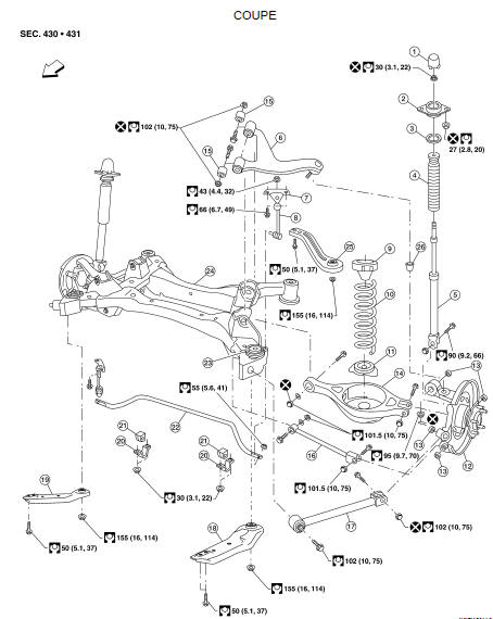

Removal and Installation
Removal
CAUTION: Before removing the rear suspension assembly, disconnect the ABS wheel sensor from the assembly.
Failure to do so may result in damage to the sensor wires and the sensor becoming inoperative.
1. Remove the center exhaust tube with muffler(s). Refer to EX-6, "Removal and Installation" (QR25DE) or EX-12, "Removal and Installation" (VQ35DE).
2. Remove brake caliper assembly and reposition aside, without disconnecting the hydraulic hose, using power tools. Refer to BR-35, "BRAKE CALIPER ASSEMBLY : Exploded View".
• Leave the brake hydraulic hose connected to the brake caliper.
• Do not depress the brake pedal, or the caliper piston will pop out.
• Do not pull or twist the brake hydraulic hose.
3. Remove brake rotor. Refer to BR-35, "BRAKE CALIPER ASSEMBLY : Exploded View".
4. Disconnect parking brake cable from knuckle. Refer to PB-6, "PEDAL TYPE : Exploded View" (pedal type), PB-7, "LEVER TYPE : Exploded View" (lever type).
5. Remove rear wheel sensors. Refer to BRC-63, "Removal and Installation" (ABS), BRC-134, "Removal and Installation" (TCS/ABS), BRC-236, "Removal and Installation" (VDC/TCS/ABS).
6. Remove lower shock absorber nuts using power tools.
7. Remove lower control arm link adjusting bolt and arm. Refer to RSU-13, "Removal and Installation".
8. Remove upper ball joint nut and cotter pin. Refer to RSU-10, "Exploded View".
9. Disconnect radius rod member side. Refer to RSU-15, "Removal and Installation".
10. Disconnect lower link adjusting bolt. Refer to RSU-14, "Removal and Installation".
11. Remove knuckle. Refer to RSU-10, "Exploded View".
12. Remove stabilizer bar. Refer to RSU-16, "Removal and Installation".
13. Disconnect lower link adjusting bolt. Refer to RSU-14, "Removal and Installation".
14. Disconnect member harness.
15. Support the rear suspension assembly using a suitable jack.
16. Remove the suspension member nuts and member stay bolts using power tools.
17. Lower the rear suspension assembly.
Installation
Installation is in the reverse order of removal.
• Check the rear wheel alignment and adjust if necessary. Refer to RSU-18, "Rear Wheel Alignment (Unladen*)".
 On-vehicle maintenance
 On-vehicle repair