Nissan Altima (L32) 2007-2012 Service Manual: On-vehicle repair
ACCELERATOR CONTROL SYSTEM
Exploded View
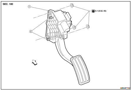
1. Accelerator pedal and accelerator position sensor assembly.
2. Locating pins

Removal and Installation
REMOVAL
1. Disconnect the battery negative terminal.
2. Disconnect the accelerator position sensor electrical connector.
3. Remove the three accelerator pedal nuts.
4. Remove the accelerator pedal and accelerator position sensor assembly.
• For electrical inspection of the accelerator pedal position sensor. Refer to EC-429, "Component Inspection" (QR25DE for California), EC-938, "Component Inspection" (QR25DE Except for Calfornia), EC- 1461, "Component Inspection" (VQ35DE).
CAUTION: • Do not disassemble the pedal assembly. Do not remove the accelerator pedal position sensor from the pedal assembly.
• Avoid impact from dropping during handling.
• Keep the pedal assembly away from water.
INSTALLATION
Installation is in the reverse order of removal.
• Align and install accelerator pedal and accelerator position sensor assembly with locating pins in locating pin holes.
• Check the accelerator pedal for smooth operation. There should be no binding or sticking when applying or releasing the accelerator pedal.
• Check that the accelerator pedal moves through the full specified distance of pedal travel.

CAUTION: When the harness connector of the accelerator pedal position sensor is disconnected, perform the “Accelerator pedal released position learning”. Refer to EC-29, "ACCELERATOR PEDAL RELEASED POSITION LEARNING : Special Repair Requirement" (QR25DE for California), EC-565, "ACCELERATOR PEDAL RELEASED POSITION LEARNING : Special Repair Requirement" (QR25DE except for California), EC-1053, "ACCELERATOR PEDAL RELEASED POSITION LEARNING : Special Repair Requirement" (VQ35DE).
 Precaution
 Service data and specifications
(SDS)
Service data and specifications
(SDS)