Nissan Altima (L32) 2007-2012 Service Manual: P1720 VSS
Description
ECM receives two vehicle speed signals via the CAN communication line. One is sent from “ABS actuator and electric unit (control unit)” via the combination meter, and the other is from TCM (Transmission control module).
ECM uses these signals for engine control.
DTC Logic
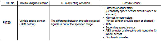
DTC DETECTION LOGIC
NOTE: • If DTC P1720 is displayed with DTC UXXXX first perform the trouble diagnosis for DTC UXXXX. Refer to EC-1179, "DTC Logic".
• If DTC P1720 is displayed with DTC P0607, first perform the trouble diagnosis for DTC P0607. Refer to EC-1378, "DTC Logic".
DTC CONFIRMATION PROCEDURE
1.PRECONDITIONING
If DTC Confirmation Procedure has been previously conducted, always perform the following before conducting the next test.
1. Turn ignition switch OFF and wait at least 10 seconds.
2. Turn ignition switch ON.
3. Turn ignition switch OFF and wait at least 10 seconds.
>> GO TO 2.
2.PERFORM DTC CONFIRMATION PROCEDURE
1. Start engine.
2. Drive vehicle at a speed of 20 km/h (12 MPH) or more for at least 5 seconds without depressing the brake pedal.
3. Check 1st trip DTC.
Is 1st trip DTC detected? YES >> Go to EC-1426, "Diagnosis Procedure".
NO >> INSPECTION END
Diagnosis Procedure
1.CHECK DTC WITH TCM
Check DTC with TCM. Refer to TM-221, "DTC Index".
Is the inspection result normal? YES >> GO TO 2.
NO >> Perform trouble shooting relevant to DTC indicated.
2.CHECK DTC WITH “ABS ACTUATOR AND ELECTRIC UNIT (CONTROL UNIT)”
Refer to BRC-223, "DTC No. Index".
Is the inspection result normal? YES >> GO TO 3.
NO >> perform trouble shooting relevant to DTC indicated.
3.CHECK COMBINATION METER FUNCTION
Refer to MWI-95, "DTC Index".
>> INSPECTION END
 P1715 Input speed sensor (primary speed sensor)
 P1800 Vias control solenoid valve 1