Nissan Altima (L32) 2007-2012 Service Manual: P2014 tumble control valve position sensor
Description
Tumble control valve position sensor is built into the tumble control valve actuator (2).
1 : Intake manifold adapter
3 : Tumble control valve
The sensor consists of a permanent magnet and Hall IC. It senses the valve shaft movement and feeds the voltage signals to the ECM.
DTC Logic
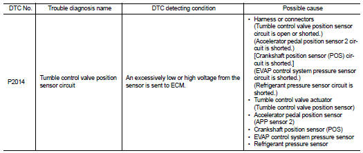
DTC DETECTION LOGIC
DTC CONFIRMATION PROCEDURE
1.PRECONDITIONING
If DTC Confirmation Procedure has been previously conducted, always turn ignition switch OFF and wait at least 10 seconds before conducting the next test.
TESTING CONDITION: Before performing the following procedure, confirm that battery voltage is more than 11V at idle.
>> GO TO 2.
2.PERFORM DTC CONFIRMATION PROCEDURE
1. Start engine and let it idle for 5 seconds.
2. Check 1st trip DTC.
Is 1st trip DTC detected? YES >> Go to EC-414, "Diagnosis Procedure".
NO >> INSPECTION END
Diagnosis Procedure
1.CHECK GROUND CONNECTION
1. Turn ignition switch OFF.
2. Check ground connection E9. Refer to Ground Inspection in GI-45, "Circuit Inspection".
Is the inspection result normal? YES >> GO TO 2.
NO >> Repair or replace ground connection.
2.CHECK TUMBLE CONTROL VALVE POSITION SENSOR POWER SUPPLY CIRCUIT-I
1. Reconnect ECM harness connector disconnected.
2. Turn ignition switch ON.
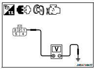
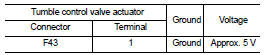
3. Check the voltage between tumble control valve actuator harness connector and ground.
Is the inspection result normal? YES >> GO TO 8.
NO >> GO TO 3.
3.CHECK TUMBLE CONTROL VALVE POSITION SENSOR POWER SUPPLY CIRCUIT-II
1. Turn ignition switch OFF.
2. Disconnect ECM harness connector.
3. Check the continuity between tumble control valve actuator harness connector and ECM harness connector.
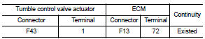
Is the inspection result normal? YES >> GO TO 4.
NO >> Repair open circuit.
4.CHECK TUMBLE CONTROL VALVE POSITION SENSOR POWER SUPPLY CIRCUIT-III
Check harness for short to power and short to ground, between the following terminals.
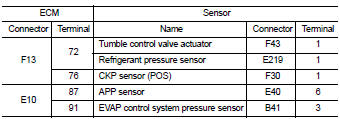
Is the inspection result normal? YES >> GO TO 5.
NO >> Repair short to ground or short to power in harness or connectors.
5.CHECK COMPONENTS
Check the following.
• Refrigerant pressure sensor (Refer to EC-482, "Diagnosis Procedure".) • Crankshaft position sensor (POS) (Refer to EC-281, "Component Inspection".) • EVAP control system pressure sensor (Refer to EC-318, "Component Inspection".) Is the inspection result normal? YES >> GO TO 6.
NO >> Replace malfunctioning components.
6.CHECK APP SENSOR
Refer to EC-429, "Component Inspection".
Is the inspection result normal? YES >> GO TO 10.
NO >> GO TO 7.
7.REPLACE ACCELERATOR PEDAL ASSEMBLY
1. Replace accelerator pedal assembly.
2. Go to EC-429, "Special Repair Requirement".
>> INSPECTION END
8.CHECK TUMBLE CONTROL VALVE POSITION SENSOR GROUND CIRCUIT FOR OPEN AND SHORT
1. Turn ignition switch OFF.
2. Disconnect ECM harness connector.
3. Check the continuity between tumble control valve actuator harness connector and ECM harness connector.
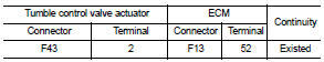
4. Also check harness for short to ground and short to power.
Is the inspection result normal? YES >> GO TO 9.
NO >> Repair open circuit or short to ground or short to power in harness or connectors.
9.CHECK TUMBLE CONTROL VALVE POSITION SENSOR INPUT SIGNAL CIRCUIT FOR OPEN AND SHORT
1. Check the continuity between tumble control valve actuator harness connector and ECM harness connector.
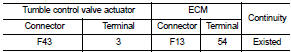
2. Also check harness for short to ground and short to power.
Is the inspection result normal? YES >> GO TO 10.
NO >> Repair open circuit or short to ground or short to power in harness or connectors.
10.CHECK INTERMITTENT INCIDENT
Refer to GI-42, "Intermittent Incident".
Is the inspection result normal? YES >> Replace intake manifold adapter.
NO >> Repair or replace harness or connectors.
 P2004 tumble control valve
 P2100, P2103 throttle control motor
relay
P2100, P2103 throttle control motor
relay