Nissan Altima (L32) 2007-2012 Service Manual: Power consumption control system
System Diagram
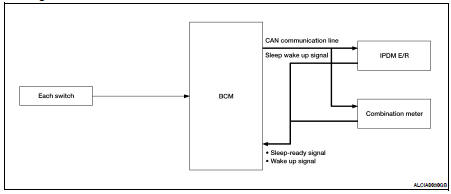
System Description
OUTLINE
• IPDM E/R incorporates a power consumption control function that reduces the power consumption according to the vehicle status.
• IPDM E/R changes its status (control mode) with the sleep wake up signal received from BCM via CAN communication.
Normal mode (wake-up)
- CAN communication is normally performed with other control units.
- Individual unit control by IPDM E/R is normally performed.
Low power consumption mode (sleep)
- Low power consumption control is active.
- CAN transmission is stopped.
SLEEP MODE ACTIVATION
• IPDM E/R judges that the sleep-ready conditions are fulfilled when the ignition switch is OFF and none of the conditions below are present. Then it transmits a sleep-ready signal (ready) to BCM via CAN communication.
- Front wiper fail-safe operation
- Outputting signals to actuators
- Switches or relays operating
- Auto active test is starting
- Emergency OFF
- Output requests are being received from control units via CAN communication.
• IPDM E/R stops CAN communication and enters the low power consumption mode when it receives a sleep wake up signal (sleep) from BCM and the sleep-ready conditions are fulfilled.
WAKE-UP OPERATION
• IPDM E/R changes from the low power consumption mode to the normal mode when it receives a sleep wake-up signal (wake up) from BCM or any of the following conditions is fulfilled. In addition, it transmits a sleep-ready signal (not-ready) to BCM via CAN communication to report the CAN communication start.
- Ignition switch ON
- An output request is received from a control unit via CAN communication.
Component Parts Location
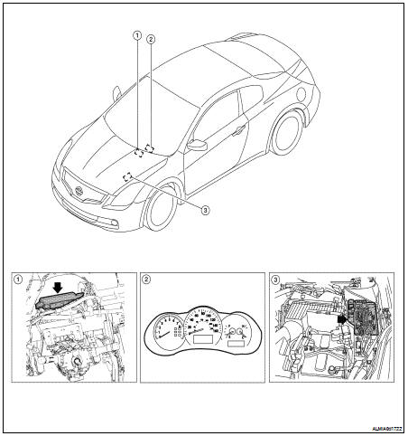
1. BCM M16, M17, M18, M19, M20, M21 (view with instrument panel removed)
2. Combination meter M24
3. IPDM E/R E16, E17, E18, E200, E201, F10
 Signal buffer system
 Diagnosis system (IPDM E/R)