Nissan Altima (L32) 2007-2012 Service Manual: Power control system
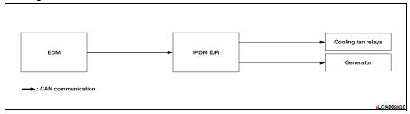
System Diagram
System Description
COOLING FAN CONTROL
IPDM E/R controls cooling fans according to the status of the cooling fan
speed request signal received from
ECM via CAN communication. Refer to LAN-7, "System Description".
GENERATOR CONTROL
IPDM E/R outputs power generation command signal (PWM signal) to the
generator according to the status of
the power generation command value signal received from ECM via CAN
communication. Refer to PCS-10,
"System Description".
System Diagram
System Description
IPDM E/R activates the internal control circuit to perform the relay ON-OFF
control according to the input signals
from various sensors and the request signal ...
System Diagram
System Description
• IPDM E/R reads the status of the oil pressure switch and transmits the oil
pressure switch signal to BCM via
CAN communication. Refer to PCS-11, "Syst ...
 Relay control system
 Signal buffer system