Nissan Altima (L32) 2007-2012 Service Manual: Rear bumper
Removal and Installation
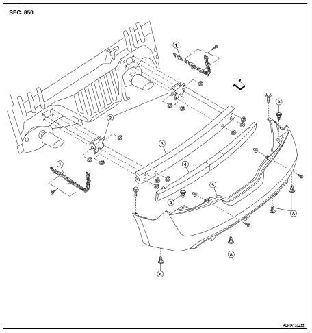
1. Rear bumper side brackets
2. Rear bumper supports
3. Rear bumper reinforcement
4. Rear energy absorbing foam
5. Rear bumper fascia
A. C205 push pin
REMOVAL
1. Remove the LH and RH rear combination lamps. Refer to EXL-260, "Removal
and Installation".
2. Remove both the rear wheels and tires. Refer to WT-66, "Adjustment".
3. Remove the rear bumper fascia clips and screws, then remove the rear bumper
fascia.
4. Remove the rear energy absorbing foam.
5. Remove the rear bumper reinforcement.
6. Remove the rear bumper supports.
INSTALLATION
Installation is in the reverse order of removal.
Removal and Installation
1. Front bumper supports
2. Front bumper side bracket
3. Reinforcement bracket
4. Front bumper reinforcement
5. Front energy absorbing foam
6. Front bumper fascia
7. ...
Removal and Installation
1. Front bumper fascia
2. Front grille
3. License plate bracket
4. Fog lamp finisher (if equipped)
5. Fog lamp (if equipped)
A. Clip C101
Removal
1. Remove the fron ...
Other materials: Programming HomeLink
If you have any questions or are having
difficulty programming your HomeLink
buttons, refer to the HomeLink website at:
www.homelink.com or call 1-800-355-3515.
NOTE:
Place the ignition switch in the ON position
(without starting the engine) when
programming HomeLink. It is also recommended that
ane ...
Seat belt warning light and chime
The driver and front passenger seat is
equipped with an enhanced seat belt reminder
function.
A visual and audible alert will operate at
speeds of approximately 9 mph (15 km/h)
or more under the following conditions:
If the driver seat belt is not fastened.
The front passenger’s seat belt is ...
Precautions on seat belt usage
If you are wearing your seat belt properly
adjusted and you are sitting upright and
well back in your seat with both feet on the
floor, your chances of being injured or killed
in a collision and/or the severity of injury
may be greatly reduced. NISSAN strongly
encourages you and all of your passeng ...

 Front bumper
 Front grille