Nissan Altima (L32) 2007-2012 Service Manual: Rear view monitor system (coupe)
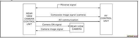
System Diagram
System Description
When the selector is in the R position, the display shows a view to the rear
of the vehicle. Lines which indicate
the vehicle clearance and distances are also displayed.
AV COMMUNICATION LINE
The rear view camera control unit is connected to the AV control unit using
an AV communication line. This
line is used to transmit and receive data.
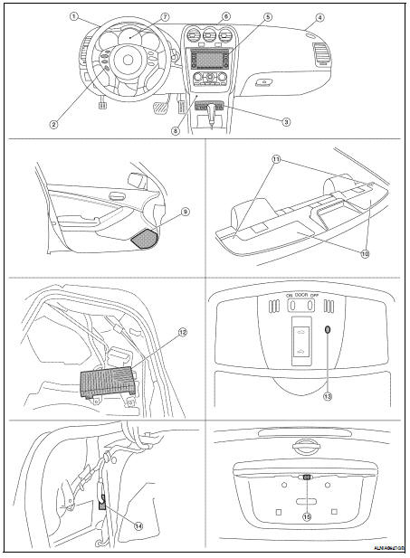
Component Parts Location
1. Front tweeter LH M51
2. Steering wheel audio control switches
3. CD changer M42
4. Front tweeter RH M52
5. AV control unit M46, M47, M48, M81,
M90, M91
6. Center speaker M151
7. Combination meter M24
8. Aux Jack M41
9. Door speaker
LH D3
RH D103
10. Rear subwoofer
LH B25
RH B47
11. Rear tweeter
LH B16
RH B100
12. BOSE speaker amp. B121, B122 (view
with trunk carpet and RH floor spacer
removed)
13. Microphone R7
14. Rear view camera control unit B31
(view with trunk side finisher LH removed)
System Diagram
System Description
NOTE:
Refer to NAVI System Owner's Manual for system operation.
The navigation system periodically calculates the vehicle's current
position according to the f ...
System Diagram
System Description
When the selector is in the R position, the display will show a view to the
rear of the vehicle. Lines which indicate
the vehicle clearance and distances are ...
 Navigation system (sedan)
 Rear view monitor system (sedan)