Nissan Altima (L32) 2007-2012 Service Manual: Shift mechanism
System Diagram
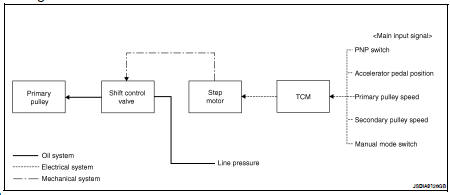
NOTE: The gear ratio is set for every position separately.
System Description
In order to select the gear ratio which can obtain the driving force in accordance with driver's intention and the vehicle condition, TCM monitors the driving conditions, such as the vehicle speed and the throttle position and selects the optimum gear ratio, and determines the gear change steps to the gear ratio. Then send the command to the step motor, and control the flow-in/flow-out of line pressure from the primary pulley to determine the position of the moving-pulley and control the gear ratio.
“D” POSITION
Shifting over all the ranges of gear ratios from the lowest to the highest.
“M” POSITION
When the selector lever is put in the manual shift gate side, the fixed changing gear line is set. By moving the selector lever to + side or - side, the manual mode switch is changed over, and shift change like M/T becomes possible following the changing gear set line step by step.
DOWNHILL ENGINE BRAKE CONTROL (AUTO ENGINE BRAKE CONTROL)
When downhill is detected with the accelerator pedal released, the engine brake will be strengthened up by downshifting so as not to accelerate the vehicle more than necessary.
ACCELERATION CONTROL
According to vehicle speed and a change of accelerator pedal angle, driver's request for acceleration and driving scene are judged. This function assists improvement in acceleration feeling by making the engine speed proportionate to the vehicle speed. And a shift map which can gain a larger driving force is available for compatibility of mileage with driveability.
Component Parts Location - Coupe
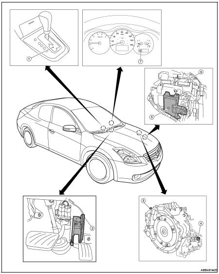
1. Control device assembly (Manual mode select switch and manual mode position select switch)
2. Accelerator pedal position (APP) sensor
3. Secondary speed sensor
4. CVT unit harness connector
5. TCM
6. Battery
7. Shift position indicator Manual mode indicator
Component Parts Location - Sedan

1. Control device assembly (Manual mode select switch and manual mode position select switch)
2. Accelerator pedal position (APP) sensor
3. Secondary speed sensor
4. CVT unit harness connector
5. TCM
6. Battery
7. Shift position indicator Manual mode indicator
Component Description
TRANSAXLE ASSEMBLY
EXCEPT TRANSAXLE ASSEMBLY

 Lock-up and select control system
 Shift lock system