Nissan Altima (L32) 2007-2012 Service Manual: Side curtain air bag module
Exploded View
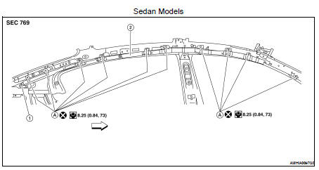
1. Side curtain air bag module connector
2. Side curtain air bag module
A. Side curtain air bag module bolt

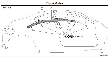
1. Side curtain air bag module
2. Side curtain air bag module inflator
A. Side curtain air bag module bolt
Removal and Installation
REMOVAL
CAUTION: • Before servicing, turn ignition switch OFF, disconnect both battery terminals and wait at least three minutes.
• Do not use air tools or electric tools for servicing.
• Always work from the side of air bag module. Do not work from the front of it.
• Always place the curtain air bag module with air bag deployment side facing upward.
• Do not cause impact to the air bag module by dropping etc. Replace the air bag module if it has been dropped or sustained an impact.
1. Disconnect the negative and positive battery terminals, then wait at least three minutes.
2. Remove the headlining. Refer to INT-20, "Removal and Installation".
3. Disconnect the side curtain air bag module connector.
• For installing/removing direct-connect SRS connectors, refer to SRC-9, "Direct-connect SRS Component Connectors".
4. Remove the bolts, then remove side curtain air bag module.
INSTALLATION
Installation is in the reverse order of removal.
CAUTION: • Be careful not to damage the air bag harness.
• After the work is completed, make sure no system malfunction is detected by air bag warning lamp.
• In case a malfunction is detected by the air bag warning lamp, reset by the self-diagnosis function and delete the memory by CONSULT-lIl.
• If a malfunction is still detected after the above operation, perform self-diagnosis to repair malfunctions.
Refer to SRC-12, "SRS Operation Check".
• Make sure the side curtain air bag module is not twisted at any point along the vehicle when installed.
 Front passenger air bag module
 Crash zone sensor