Nissan Altima (L32) 2007-2012 Service Manual: Sound signal circuit (coupe)
SATELLITE RADIO TUNER
Description
Left and right channel audio signals are supplied from the satellite radio tuner to the audio unit through the sound signal circuits.
Diagnosis Procedure
LEFT CHANNEL
1.CHECK HARNESS
1. Turn ignition switch OFF.
2. Disconnect satellite radio tuner (factory installed) connector B57 and audio unit connector M45.
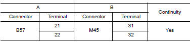
3. Check continuity between satellite radio tuner (factory installed) connector B57 (A) and audio unit connector M45 (B).
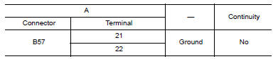
4. Check continuity between satellite radio tuner (factory installed) connector B57 (A) and ground.
Are continuity results as specified? YES >> GO TO 2
NO >> Repair harness or connector.
2.CHECK LEFT CHANNEL AUDIO SIGNAL
1. Connect satellite radio tuner (factory installed) and audio unit.
2. Turn ignition switch ON.
3. Check signal between satellite radio tuner (factory installed) connector B57 terminals 21 and 22 with CONSULT-III or oscilloscope.

Are voltage readings as specified? YES >> Replace audio unit. Refer to AV-215, "Removal and Installation".
NO >> Replace satellite radio tuner. Refer to AV-223, "Removal and Installation - Coupe".
RIGHT CHANNEL
1.CHECK HARNESS
1. Turn ignition switch OFF.
2. Disconnect satellite radio tuner (factory installed) connector B57 and audio unit connector M45.
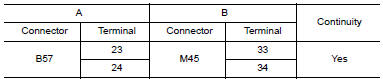
3. Check continuity between satellite radio tuner (factory installed) connector B57 (A) and audio unit connector M45 (B).
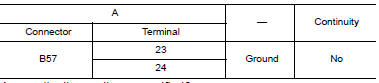
4. Check continuity between satellite radio tuner (factory installed) connector B57 (A) and ground.
Are continuity results as specified? YES >> GO TO 2
NO >> Repair harness or connector.
2.CHECK RIGHT CHANNEL AUDIO SIGNAL
1. Connect satellite radio tuner (factory installed) and audio unit.
2. Turn ignition switch ON.
3. Check signal between satellite radio tuner (factory installed) connector B57 terminals 23 and 24 with CONSULT-III or oscilloscope.

Are voltage readings as specified? YES >> Replace audio unit. Refer to AV-215, "Removal and Installation".
NO >> Replace satellite radio tuner. Refer to AV-223, "Removal and Installation - Coupe".
 Communication signal circuit (sedan) satellite radio tuner
 Sound signal circuit (sedan)