Array ( [2] =>

Foreword
Welcome to the growing family of new NISSAN owners. This vehicle is delivered to you with confidence. It was produced using the latest techniques and strict quality control. This manual was prepared to help you understand the operation and maintenance of your vehicle so that you may enjoy ma ...

[3] =>

Read first—then drive safely
Before driving your vehicle, please read this Owner’s Manual carefully. This will ensure familiarity with controls and maintenance requirements, assisting you in the safe operation of your vehicle. Warning Important safety information reminders for safety! Follow these important driving ru ...

[4] =>

When reading the manual
This manual includes information for all features and equipment available on this model. Features and equipment in your vehicle may vary depending on model, trim level, options selected, order, date of production, region or availability. Therefore, you may find information about features or eq ...

[5] =>

NISSAN customer care program
NISSAN CARES . . . Both NISSAN and your NISSAN dealer are dedicated to serving all your automotive needs. Your satisfaction with your vehicle and your NISSAN dealer are our primary concerns. Your NISSAN dealer is always available to assist you with all your automobile sales and service needs. ...

[7] =>

Air bags, seat belts and child restraints
1. Top tether strap anchor 2. Rear seat belts 3. Roof-mounted curtain side-impact supplemental air bag 4. Front seat-mounted side-impact supplemental air bag 5. Head restraints/headrests 6. Front seat belts 7. Side-impact pressure sensor (driver’s side shown; passenger’s side simil ...

[8] =>

Exterior front
1. Power windows 2. Windshield 3. Windshield wiper and washer switch 4. Engine hood 5. Tie down 6. Fog light switch (if so equipped) 7. Headlight and turn signal switch 8. Replacing bulbs 9. Tire pressure 10. Flat tire 11. Tire chains 12. Mirrors 13. Door locks, NISSAN Intelligen ...

[10] =>

Passenger compartment
1. Interior trunk access 2. Moonroof (if so equipped) 3. Sun visors 4. Interior lights, illuminated entry 5. HomeLink® universal transceiver (if so equipped) 6. Automatic anti-glare rearview mirror (if so equipped) 7. Glove box 8. Cup holders 9. Console box 10. Front seat 11. Re ...

[11] =>

Instrument panel
1. Instrument brightness control/Trip computer reset switch 2. Vents 3. Headlight/fog light (if so equipped)/turn signal switch 4. Driver supplemental air bag/horn 5. Meters and gauges 6. Paddle shift controls (if so equipped) 7. Windshield wiper/washer switch 8. Hazard warning flasher ...

[12] =>

Engine compartment check locations
QR25DE engine 1. Power steering fluid reservoir 2. Engine coolant reservoir 3. Engine oil filler cap 4. Brake fluid reservoir 5. Air cleaner 6. Fuse/fusible link box 7. Battery 8. Engine oil dipstick 9. Radiator cap 10. Drive belt location 11. Windshield-washer fluid reservoir S ...

[15] =>

Seats
WARNING ● Do not ride in a moving vehicle when the seatback is reclined. This can be dangerous. The shoulder belt will not be against your body. In an accident, you could be thrown into it and receive neck or other serious injuries. You could also slide under the lap belt and receive ...

[16] =>

Front manual seat adjustment (if so equipped
Forward and backward Pull the center of the bar up and hold it while you slide the seat forward or backward to the desired position. Release the bar to lock the seat in position. Reclining To recline the seatback, pull the lever up and lean back. To bring the seatback forward, pull the le ...

[17] =>

Front power seat adjustment (if so equipped for driver’s seat)
Operating tips WARNING Before driving the vehicle, return the seatback to an upright seating position after manually releasing it. Also, make sure the seat is locked in place. Failure to do so may cause the seat to move in a collision or sudden stop. This may result in damage to the seat o ...

[18] =>

Folding rear seat
Interior trunk access The trunk can be accessed from the driver side (if so equipped) and passenger side of the rear seat for loading and unloading, as shown. 1. Move the front passenger seat to the most forward position. 2. Open the access cover on the rear parcel shelf. 3. Push down on the ...

[19] =>

Front seat head restraints/headrests
WARNING ● Head restraints/headrests supplement the other vehicle safety systems. They may provide additional protection against injury in certain rear end collisions. Adjust the head restraints/headrests properly, as specified in this section. Check the adjustment after someone else ...

[20] =>

Rear seat head restraints/headrests
WARNING ● Head restraints/headrests supplement the other vehicle safety systems. They may provide additional protection against injury in certain rear end collisions. Adjust the head restraints/headrests properly, as specified in this section. Check the adjustment after someone else ...

[22] =>

Precautions on seat belt usage
If you are wearing your seat belt properly adjusted and you are sitting upright and well back in your seat with both feet on the floor, your chances of being injured or killed in an accident and/or the severity of injury may be greatly reduced. NISSAN strongly encourages you and all of your ...

[25] =>

Three-point type seat belt with retractor
WARNING ● Every person who drives or rides in this vehicle should use a seat belt at all times. ● Do not ride in a moving vehicle when the seatback is reclined. This can be dangerous. The shoulder belt will not be against your body. In an accident, you could be thrown into it and ...

[26] =>

Seat belt extenders
If, because of body size or driving position, it is not possible to properly fit the lap/shoulder belt and fasten it, an extender that is compatible with the installed seat belts is available that can be purchased. The extender adds approximately 8 in (200 mm) of length and may be used for eith ...

[27] =>

Seat belt maintenance
● To clean the seat belt webbing, apply a mild soap solution or any solution recommended for cleaning upholstery or carpet. Then wipe with a cloth and allow the seat belts to dry in the shade. Do not allow the seat belts to retract until they are completely dry. ● If dirt builds ...

[28] =>

Child safety
WARNING Do not allow children to play with the seat belts. Most seating positions are equipped with Automatic Locking Retractor (ALR) mode seat belts. If the seat belt becomes wrapped around a child’s neck with the ALR mode activated, the child can be seriously injured or killed if the seat ...

[30] =>

Small children
Children that are over 1 year old and weigh at least 20 lbs (9 kg) should remain in a rear-facing child restraint as long as possible up to the height or weight limit of the child restraint. Children who outgrow the height or weight limit of the rearfacing child restraint and are at least 1 yea ...

[31] =>

Larger children
Children should remain in a forward-facing child restraint with a harness until they reach the maximum height or weight limit allowed by the child restraint manufacturer. Once a child outgrows the height or weight limit of the harness-equipped forward-facing child restraint, NISSAN recommends ...

[33] =>

Precautions on child restraints
WARNING Failure to follow the warnings and instructions for proper use and installation of child restraints could result in serious injury or death of a child or other passengers in a sudden stop or collision: – The child restraint must be used and installed properly. Always follow all ...

[34] =>

LATCH (Lower Anchors and Tethers for CHildren) System
LATCH system anchor locat Your vehicle is equipped with special anchor points that are used with LATCH (Lower Anchors and Tethers for CHildren) system compatible child restraints. This system may also be referred to as the ISOFIX or ISOFIX compatible system. With this system, you do not ha ...

[35] =>

Rear-facing child restraint installation using LATCH
Refer to all Warnings and Cautions in the “Child Safety” and “Child Restraint” sections before installing a child restraint. Follow these steps to install a rear-facing child restraint using the LATCH system: 1. Position the child restraint on the seat. Always follow the child restra ...

[36] =>

Rear-facing child restraint installation using the seat belts
WARNING The three-point seat belt with Automatic Locking Retractor (ALR) must be used when installing a child restraint. Failure to use the ALR mode will result in the child restraint not being properly secured. The restraint could tip over or be loose and cause injury to a child in a sudde ...

[37] =>

Forward-facing child restraint installation using LATCH
Refer to all Warnings and Cautions in the “Child Safety” and “Child Restraint” sections before installing a child restraint. Follow these steps to install a forward-facing child restraint using the LATCH system: 1. Position the child restraint on the seat. Always follow the child res ...

[38] =>

Forward-facing child restraint installation using the seat belts
WARNING The three-point seat belt with Automatic Locking Retractor (ALR) must be used when installing a child restraint. Failure to use the ALR mode will result in the child restraint not being properly secured. The restraint could tip over or be loose and cause injury to a child in a sudden ...

[39] =>

Installing top tether strap
First, secure the child restraint with the LATCH lower anchors (rear outboard seat positions only) or the seat belt, as applicable. 1. Flip up the anchor cover 1 from the anchor point which is located directly behind the child seat. 2. Position the top tether strap over the top of the hea ...

[40] =>

Booster seats
Precautions on booster seats WARNING If a booster seat and seat belt are not used properly, the risk of a child being injured in a sudden stop or collision greatly increases: – Make sure the shoulder portion of the belt is away from the child’s face and neck and the lap portion of the b ...

[42] =>

Precautions on supplemental restraint system
This Supplemental Restraint System (SRS) section contains important information concerning the following systems: ● Driver and passenger supplemental frontimpact air bag (NISSAN Advanced Air Bag System) ● Front seat-mounted side-impact supplemental air bag ● Roof-mounted cu ...

[43] =>

Front seat-mounted side-impact supplemental air bag and roof-mounted curtain side-impact supplemental air bag systems
The side air bags are located in the outside of the seatback of the front seats. The curtain air bags are located in the side roof rails. However, all of the information, cautions and warnings in this manual still apply and must be followed. The side air bags and curtain air bags are desig ...

[44] =>

Seat belts with pretensioners (Front seats)
WARNING ● The pretensioners cannot be reused after activation. They must be replaced together with the retractor and buckle as a unit. ● If the vehicle becomes involved in a collision but a pretensioner is not activated, be sure to have the pretensioner system checked and, if nec ...

[46] =>

Supplemental air bag warning light
The supplemental air bag warning light, displaying in the instrument panel, monitors the circuits for the air bag systems, pretensioners and all related wiring. When the ignition is placed in the ON or START position, the supplemental air bag warning light illuminates for about 7 second ...

[48] =>

Instrument panel
1. Instrument brightness control/Trip computer reset switch 2. Vents 3. Headlight/fog light (if so equipped)/turn signal switch 4. Driver supplemental air bag/horn 5. Meters and gauges 6. Paddle shift controls (if so equipped) 7. Windshield wiper/washer switch 8. Hazard warning flasher ...

[50] =>

Speedometer and odometer
Speedometer The speedometer indicates vehicle speed. Odometer/Twin trip odometer The odometer 1 and the twin trip odometer 2 are displayed below the Vehicle Information Display when the ignition switch is placed in the ON position. The odometer records the total distance the vehicle ha ...

[52] =>

Engine coolant temperature gauge
The gauge indicates the engine coolant temperature. The engine coolant temperature is within the normal range 1 when the gauge needle points within the zone shown in the illustration. The engine coolant temperature varies with the outside air temperature and driving conditions. CAUTION ...

[53] =>

Fuel gauge
The gauge indicates the approximate fuel level in the tank. The gauge may move slightly during braking, turning, acceleration, or going up or down hills. The gauge needle returns to 0 (Empty) after the ignition switch is placed in the OFF position. The low fuel warning light comes on w ...

[54] =>

Compass display (if so equipped)
This unit measures terrestrial magnetism and indicates the direction of the vehicle’s heading. With the ignition switch placed in the ON position, press the button as described in the chart below to activate various features of the automatic anti-glare rearview mirror. For information ...

[56] =>

Checking bulbs
With all doors closed, apply the parking brake and place the ignition switch to the ON position without starting the engine. The following lights will come on: The following lights (if equipped) come on briefly and then go off: If any light fails to come on, it may indicate a burned-out b ...

[57] =>

Warning lights
For additional information on warnings and indicators, see “Vehicle information display” later in this section. Anti-lock Braking System (ABS) warning light When the ignition switch is placed in the ON position, the Anti-lock Braking System (ABS) warning light illuminates and then turns ...

[58] =>

Indicator lights
For additional information on warnings and indicators, see “Vehicle information display” later in this section. Front fog light indicator light (if so equipped) The front fog light indicator light illuminates when the front fog lights are ON. See “Fog light switch” later in this sec ...

[59] =>

Audible reminders
Brake pad wear warning The disc brake pads have audible wear warnings. When a disc brake pad requires replacement, it makes a high pitched scraping sound when the vehicle is in motion, whether or not the brake pedal is depressed. Have the brakes checked as soon as possible if the warning sou ...

[60] =>

Vehicle Information Display
The vehicle information display is located to the left of the speedometer. It displays such items as: ● Vehicle settings ● Trip computer information ● Drive system warnings and settings (if so equipped) ● Cruise control system information ● NISSAN Intelligent K ...

[61] =>

How to use the vehicle information display
The vehicle information display can be changed using the buttons and ENTER located on the steering wheel. 1. — navigate through the items in vehicle information ENTER — change or select an item in the vehicle information display 2. — go back to the previous menu 3.   ...

[62] =>

Startup display
When the vehicle in placed in the ON or ACC position the screens that display in the vehicle information include: ● Active system status (if so equipped) ● Trip computer ● Tire pressure information (if so equipped) ● Fuel economy ● Warnings Warnings will only di ...

[63] =>

Settings
The setting mode allows you to change the information displayed in the vehicle information display: ● Driver Assistance (if so equipped) ● Main Menu Selection ● Body Color ● Maintenance ● Alarms ● Vehicle Settings ● Language ● Unit ● We ...

[64] =>

Vehicle information display warnings and indicators
1. No Key Detected 2. Key ID Incorrect 3. Shift to Park 4. Push ignition to OFF 5. Key Battery Low 6. Engine start operation for Intelligent Key system 7. Release parking brake 8. Low Fuel 9. Low Washer Fluid 10. Door Open 11. Trunk Open 12. Timer Alert – Time for a driver break? 13 ...

[66] =>

Vehicle security system
audible alarm signals if someone opens the doors, trunk lid or the hood when the system is armed. It is not, however, a motion detection type system that activates when a vehicle is moved or when a vibration occurs. The system helps deter vehicle theft but cannot prevent it, nor can it preve ...

[67] =>

NISSAN vehicle immobilizer system
The NISSAN Vehicle Immobilizer System will not allow the engine to start without the use of a registered key. Never leave these keys in the vehicle. FCC Notice: For USA: This device complies with part 15 of the FCC Rules. Operation is subject to the following two conditions: (1) This devic ...

[68] =>

Windshield wiper and washer switch
WARNING In freezing temperatures the washer solution may freeze on the window and obscure your vision which may lead to an accident. Warm the window with the defroster before you wash the window. CAUTION ● Do not operate the washer continuously for more than 30 seconds. ● Do not ...

[69] =>

Rear window and outside mirror (if so equipped) defroster switch
Type A To defrost the rear window glass and outside mirrors (if so equipped), start the engine and push the rear window defroster switch on. The rear window defroster indicator light on the switch comes on. Push the switch again to turn the defroster off. The rear window defroster automat ...

[71] =>

Xenon headlights (if so equipped)
WARNING HIGH VOLTAGE ● When xenon headlights are on, they produce a high voltage. To prevent an electric shock, never attempt to modify or disassemble. Always have your xenon headlights replaced at a NISSAN dealer. ● Xenon headlights provide considerably more light than conventi ...

[72] =>

Headlight control switch
Lighting 1 When turning the switch to the position, the front parking, tail, license plate and instrument panel lights come on. 2 When turning the switch to the position, the headlights come on and all the other lights remain on. CAUTION Use the headlights with the engine running to a ...

[73] =>

Daytime running light system (Canada only)
The headlights automatically illuminate at a reduced intensity when the engine is started with the parking brake released. The daytime running lights operate with the headlight switch in the OFF position or in the position. Turn the headlight switch to the position for full illumination ...

[76] =>

Fog light switch (if so equipped)
To turn the fog lights on, turn the headlight switch to the position, then turn the fog light switch to the position. To turn the fog lights on with the headlight switch in the AUTOposition, the headlights must be on, then turn the fog light switch to the position. To turn the fog ...

[78] =>

Heated seats (if so equipped)
The front seats are warmed by built-in heaters. 1. Start the engine. 2. Push the LO or HI position of the switch, as desired. The indicator light in the switch will illuminate. The heater is controlled by a thermostat, automatically turning the heater on and off. The indicator light w ...

[79] =>

Heated steering wheel (if so equipped)
The heated steering wheel system is designed to operate only when the surface temperature of the steering wheel is below approximately 68°F (20°C). Push the heated steering wheel switch to warm the steering wheel after the engine starts. The indicator light will come on. If the surfac ...

[80] =>

Warning systems switch (if so equipped)
The warning systems switch is used to temporarily turn off the warning systems (Lane Departure Warning (LDW) and Blind SpotWarning (BSW) systems) that are activated using the settings menu in the vehicle information display. When the warning systems switch is turned off, the indicator 1 on ...

[81] =>

Vehicle Dynamic Control (VDC) off switch
The vehicle should be driven with the Vehicle Dynamic Control (VDC) system on for most driving conditions. If the vehicle is stuck in mud or snow, the VDC system reduces the engine output to reduce wheel spin. The engine speed will be reduced even if the accelerator is depressed to the flo ...

[82] =>

Power outlet
Instrument panel The power outlets are for powering electrical accessories such as cellular telephones. They are rated at 12 volt, 120W (10A) maximum. The power outlets are powered only when the ignition switch is in the ACC or ON position. Open the lower half of the console box to acces ...

[86] =>

Sunglasses holder
To open the sunglasses holder, push and release. Only store one pair of sunglasses in the holder. WARNING Keep the sunglasses holder closed while driving to prevent an accident. CAUTION ● Do not use for anything other than sunglasses. ● Do not leave sunglasses in the sunglass ...

[87] =>

Cup holders
Front Rear The rear center cup holders are located in the rear fold-down armrest. CAUTION ● Avoid abrupt starting and braking when the cup holder is being used to prevent spilling the drink. If the liquid is hot, it can scald you or your passenger. ● Use only soft cups in th ...

[89] =>

Console box
Upper half Pull up on the driver’s side latch to open the upper half of the console box. The upper half of the console box may be used for storage of cellular phones. An access hole is provided at the front of the upper half of the console box for phone cord routing to the power outlet. ...

[91] =>

Windows
POWER WINDOWS WARNING ● Make sure that all passengers have their hands, etc. inside the vehicle while it is in motion and before closing the windows. Use the window lock switch to prevent unexpected use of the power windows. ● Do not leave children unattended inside the vehicle. ...

[92] =>

Moonroof (if so equipped)
AUTOMATIC MOONROOF switch is placed in the ON position. The automatic moonroof is operational for a period of time, even if the ignition switch is placed in the ACC or OFF position. If the driver’s door or the front passenger’s door is opened during this period of time, the power to the ...

[93] =>

Interior light
1 The interior light can be turned ON regardless of door position. The light will go off after a period of time unless the ignition switch is placed in the ON position when any door is opened. 2 The interior lights can be set to operate when the doors are opened. To turn off the interi ...

[97] =>

HomeLink® universal transceiver (if so equipped)
The HomeLink® Universal Transceiver provides a convenient way to consolidate the functions of up to three individual hand-held transmitters into one built-in device. HomeLink® Universal Transceiver: ● Will operate most Radio Frequency (RF) devices such as garage doors, gates, home a ...

[98] =>

Programming HomeLink®
If you have any questions or are having difficulty programming your HomeLink® buttons, refer to the HomeLink® web site at: www.homelink.com or call 1-800-355-3515. NOTE: Place the ignition switch in the ACC position when programming HomeLink®. It is also recommended that a new battery be ...

[99] =>

Programming HomeLink® for Canadian customers and gate openers
Canadian radio-frequency laws require transmitter signals to “time-out” (or quit) after several seconds of transmission – which may not be long enough for HomeLink® to pick up the signal during training. Similar to this Canadian law, some U.S. gate operators are designed to “timeout” ...

[101] =>

Programming trouble-diagnosis
If the HomeLink® does not quickly learn the hand-held transmitter information: ● replace the hand-held transmitter batteries with new batteries. ● position the hand-held transmitter with its battery area facing away from the HomeLink® surface. ● press and hold both the Hom ...

[102] =>

Clearing the programmed information
The following procedure clears the programmed information from both buttons. Individual buttons cannot be cleared. However, individual buttons can be reprogrammed. See “Reprogramming a single HomeLink® button” in this section. To clear all programming: 1. Press and hold the two outer Ho ...

[103] =>

Reprogramming a single HomeLink® button
To reprogram a HomeLink® Universal Transceiver button, complete the following: 1. Press and hold the desired HomeLink® button. DO NOT release the button. 2. The indicator light will begin to flash after 20 seconds. Without releasing the HomeLink® button, proceed with “Programming HomeL ...

[104] =>

If your vehicle is stolen
If your vehicle is stolen, you should change the codes of any non-rolling code device that has been programmed into HomeLink®. Consult the Owner’s Manual of each device or call the manufacturer or dealer of those devices for additional information. When your vehicle is recovered, you will ...

[107] =>

NISSAN Intelligent Key®
Your vehicle can only be driven with the Intelligent Keys which are registered to your vehicle’s Intelligent Key system components and NISSAN Vehicle Immobilizer System components. As many as 4 Intelligent Keys can be registered and used with one vehicle. The new keys must be registered by a ...

[108] =>

NISSAN Vehicle Immobilizer System keys
You can only drive your vehicle using the master keys which are registered to the NISSAN Vehicle Immobilizer System components in your vehicle. The master key can be used for all the locks. Never leave these keys in the vehicle. Additional or replacement keys: If you still have a key, the ke ...

[109] =>

Doors
When the doors are locked using one of the following methods, the doors can not be opened using the inside or outside door handles. The doors must be unlocked to open the doors. WARNING ● Always have the doors locked while driving. Along with the use of seat belts, this provides greater ...

[110] =>

Locking with key
Driver’s side Manual (if so equipped) To lock a door, turn the key toward the front of the vehicle 1 . To unlock, turn the key toward the rear of the vehicle 2 . Power (if so equipped) The power door lock system allows you to lock or unlock all doors at the same time. Turning the key ...

[112] =>

Locking with power door lock switch
Door lock switch To lock all the doors without a key, push the door lock switch (driver’s or front passenger’s side) to the lock position 1 . When locking the door this way, be certain not to leave the key inside the vehicle. To unlock all the doors without a key, push the door lock s ...

[113] =>

Automatic door locks
● All doors lock automatically when the vehicle speed reaches 15 MPH (24 km/h). ● All doors unlock automatically when the ignition is placed in the OFF position. The automatic unlock function can be deactivated or activated. To deactivate or activate the automatic door unlock sys ...

[114] =>

Child safety rear door
Child safety locks help prevent the rear doors from being opened accidentally, especially when small children are in the vehicle. The child safety lock levers are located on the edge of the rear doors. When the lever is in the unlock position 2 , the door can be opened from the outside o ...

[115] =>

NISSAN Intelligent Key® With Door and Trunk Request Switches
WARNING ● Radio waves could adversely affect electric medical equipment. Those who use a pacemaker should contact the electric medical equipment manufacturer for the possible influences before use. ● The Intelligent Key transmits radio waves when the buttons are pressed. The F ...

[116] =>

Operating range
The Intelligent Key functions can only be used when the Intelligent Key is within the specified operating range from the request switch 1 . When the Intelligent Key battery is discharged or strong radio waves are present near the operating location, the Intelligent Key system’s operating ...

[117] =>

Door locks/unlocks precaution
● Do not push the door handle request switch with the Intelligent Key held in your hand as illustrated. The close distance to the door handle will cause the Intelligent Key system to have difficulty recognizing that the Intelligent Key is outside the vehicle. ● After locking with ...

[118] =>

NISSAN Intelligent Key® operation
You can lock or unlock the doors without taking the key out of your pocket or bag. When you carry the Intelligent Key with you, you can lock or unlock all doors by pushing the door handle request switch within the range of operation. Locking doors 1. Move the shift lever to the P (Park) ...

[119] =>

How to use the remote keyless entry function
The remote keyless entry function can operate all door locks using the remote keyless function of the Intelligent Key. The remote keyless function can operate at a distance of 33 ft (10 m) away from the vehicle. The operating distance depends upon the conditions around the vehicle. The remot ...

[120] =>

Warning signals
To help prevent the vehicle from moving unexpectedly by erroneous operation of the Intelligent Key or to help prevent the vehicle from being stolen, a chime or buzzer sounds from inside and outside the vehicle and a warning is displayed in the instrument panel. When a chime or beep sounds or ...

[122] =>

NISSAN Intelligent Key® Without Door and Trunk Request Switches
WARNING ● Radio waves could adversely affect electric medical equipment. Those who use a pacemaker should contact the electric medical equipment manufacturer for the possible influences before use. ● The Intelligent Key transmits radio waves when the buttons are pressed. The F ...

[124] =>

How to use the remote keyless entry function
The remote keyless entry function can operate all door locks using the remote keyless function of the Intelligent Key. The remote keyless function can operate at a distance of 33 ft (10 m) away from the vehicle. The operating distance depends upon the conditions around the vehicle. The remot ...

[125] =>

Warning signals
To help prevent the vehicle from moving unexpectedly by erroneous operation of the Intelligent Key or to help prevent the vehicle from being stolen, a chime or buzzer sounds from inside and outside the vehicle and a warning is displayed in the instrument panel. When a chime or beep sounds or ...

[127] =>

Remote Engine Start (if so equipped)
The button will be on the NISSAN Intelligent Key® if the vehicle has remote engine start. This feature allows the engine to start from outside the vehicle. The following features may be affected when the remote start feature is used: ● Vehicles with a manual climate control sys ...

[129] =>

Remote starting the vehicle
perform the following: 1. Aim the Intelligent Key at the vehicle. 2. Press the LOCK button to lock all doors. 3. Within 5 seconds press and hold the remote start button until the turn signal lights illuminate. If the vehicle is not within view press and hold the remote start butto ...

[130] =>

Extending engine run time
The remote start feature can be extended one time by performing the steps listed in “Remote starting the vehicle” in this section. Run time will be calculated as follows: ● The first 10 minute run time will start when the remote start function is performed. ● The second 10 minu ...

[132] =>

Conditions the remote start will not work
The remote start will not operate if any of the following conditions are present: ● The ignition switch is placed in the ON position. ● The hood is not securely closed. ● The hazard warning lights are on. ● The I–Key Indicator Light remains solid in the vehicle inform ...

[133] =>

Hood
1 Pull the hood lock release handle located below the driver’s side instrument panel; the hood springs up slightly. 2 Push the lever at the front of the hood to the side as illustrated with your fingertips and raise the hood. 3 Remove the support rod from the clamp. 4 Insert the support r ...

[135] =>

Opener operation
Instrument panel WARNING ● Do not drive with the trunk lid open. This could allow dangerous exhaust gases to be drawn into the vehicle. See “Exhaust gas” in the “Starting and driving” section of this manual. Intelligent Key ● Closely supervise children when they are ...

[136] =>

Interior trunk lid release
WARNING Closely supervise children when they are around cars to prevent them from playing and becoming locked in the trunk where they could be seriously injured. Keep the car locked, with the rear seatback and trunk lid securely latched when not in use, and prevent children’s access to ca ...

[139] =>

Fuel-filler cap
WARNING ● Gasoline is extremely flammable and highly explosive under certain conditions. You could be burned or seriously injured if it is misused or mishandled. Always stop the engine and do not smoke or allow open flames or sparks near the vehicle when refueling. ● Do not a ...

[142] =>

Telescopic operation
Pull the lock lever down 1 and adjust the steering wheel forward or backward 3 to the desired position. Push the lock lever up 1 firmly to lock the steering wheel in place. WARNING Do not adjust the steering wheel any closer to you than is necessary for proper steering operation and comfor ...

[143] =>

Sun visors
1 To block glare from the front, swing down the main sun visor. 2 To block glare from the side, remove the main sun visor from the center mount and swing the visor to the side. 3 To extend (if so equipped) the sun visor, slide in or out as needed. CAUTION ● Do not store the sun visor ...

[146] =>

Automatic anti-glare rearview mirror (if so equipped)
The inside mirror is designed so that it automatically dims during night time conditions and according to the intensity of the headlights of the vehicle following you. The automatic anti-glare feature is activated when the ignition switch is in the ON position. The indicator light will illum ...

[147] =>

Outside mirrors
WARNING ● Do not adjust the mirrors while driving. You could lose control of your vehicle and cause an accident. ● Objects viewed in the outside mirror on the passenger side are closer than they appear. Be careful when moving to the right. Using only this mirror could cause a ...

[148] =>

Monitor, climate, audio, phone and voice recognition systems
WARNING ● Positioning of the heating or air conditioning controls and display controls should not be done while driving in order that full attention may be given to the driving operation. ● Do not disassemble or modify this system. If you do, it may result in accidents, fire, o ...

[149] =>

Control panel buttons — color screen with Navigation System (if so equipped)
1. PWR button/VOL (volume) control knob 2. Display screen 3. ENTER / AUDIO button / TUNE / SCROLL knob 4. BACK button 5. MAP button* 6. NAV button* 7. button 8. (brightness control) button 9. button** 10. CAMERA button * For information regarding the Navigation system control butto ...

[150] =>

How to use the touch screen
CAUTION ● The glass display screen may break if it is hit with a hard or sharp object. If the glass screen breaks, do not touch it. Doing so could result in an injury. ● To clean the display, never use a rough cloth, alcohol, benzine, thinner or any kind of solvent or paper towe ...

[152] =>

How to use the APPS button
For more information about the “SiriusXM Travel Link”, and “SiriusXM Traffic” features, see the separate Navigation System Owner’s Manual. For more information about the “My Apps” key, see “NissanConnect APP Smartphone Integration (if so equipped)” in this section. For ...

[153] =>

 button
To change the display brightness, press the button. Pressing the button again will change the display to the day or the night display. If no operation is performed within 5 seconds, the display will return to the previous display. Press and hold the button for more than two seconds to ...

[154] =>

RearView Monitor (if so equipped)
When the shift lever is shifted into the R (Reverse) position, the monitor display shows the view to the rear of the vehicle. The system is designed as an aid to the driver in detecting large stationary objects to help avoid damaging the vehicle. The system will not detect small objects belo ...

[155] =>

How to read the displayed lines
Guiding lines which indicate the vehicle width and distances to objects with reference to the vehicle bumper line A are displayed on the monitor. Distance guide lines: Indicate distances from the vehicle body. ● Red line 1 : approx. 1.5 ft (0.5 m) ● Yellow line 2 : approx. 3 ...

[156] =>

Difference between predicted and actual distances
The distance guide line and the vehicle width guide line should be used as a reference only when the vehicle is on a level, paved surface. The distance viewed on the monitor is for reference only and may be different than the actual distance between the vehicle and displayed objects. Backing ...

[157] =>

How to adjust the screen (if so equipped)
settings, press the SETTING button while the RearView Monitor screen is displayed. Each time the SETTING button is pressed, the next setting item is selected. Turn the TUNE·SCROLL/TUNE·FOLDER control knob to adjust each item. Available setting items: ● Brightness ● Contrast &# ...

[158] =>

Operating tips
CAUTION ● Do not use alcohol, benzine or thinner to clean the camera. This will cause discoloration. To clean the camera, wipe with a cloth dampened with a diluted mild cleaning agent and then wipe with a dry cloth. ● Do not damage the camera as the monitor screen may be adversel ...

[159] =>

Rear and rear-wide view monitor with moving object detection (MOD) (if so equipped)
When the shift lever is shifted into the R (Reverse) position, the monitor display shows view to the rear of the vehicle. The system is designed as an aid to the driver in detecting large stationary objects to help avoid damaging the vehicle. The system will not detect small objects below th ...

[160] =>

How to switch the display
A : Original screen before the RearView Monitor is operated B : Rear-wide view screen C : Rear view screen 1 : Shift lever is moved into the R (Reverse) position 2 : Shift lever is moved out of the R (Reverse) position 3 : Select the “View” key on the screen ● When the shift lev ...

[161] =>

How to park with predicted course lines
WARNING ● Always turn and check that it is safe to do so before backing up. Always back up slowly. ● Use the displayed lines as a reference. The lines are highly affected by the number of occupants, fuel level, vehicle position, road conditions and road grade. ● If the ti ...

[163] =>

Operating tips
● When the shift lever is shifted to R (Reverse), the monitor screen automatically changes to the RearView Monitor mode. However, the radio can be heard. ● It may take some time until the RearView Monitor is displayed after the shift lever has been shifted to R (Reverse). Objects ...

[164] =>

Moving Object Detection (MOD) (if so equipped)
The Moving Object Detection (MOD) system can inform the driver of moving objects behind the vehicle when backing out of garages, maneuvering in parking lots and in other such instances. The MOD system detects moving objects by using image processing technology on the image shown in the displ ...

[165] =>

Vents
Side Adjust air flow direction by moving the vent slides. Open or close the vents by using the dial. Move the dial toward the to open the vents or toward the to close them. Center Rear ...

[166] =>

Heater and Air Conditioner (manual) (if so equipped)
1. Fan speed control / system OFF dial / air conditioning (A/C) button 2. Air flow control buttons 3. Temperature control dial / MAX A/C button 4. Air recirculation button 5. Rear window defroster button 6. Front windshield defrost button WARNING ● The air conditioner cooling functi ...

[167] =>

Controls
Fan control dial The fan control dial turns the fan on and off, and controls fan speed. Air flow control buttons The air flow control buttons allow you to select the air flow outlets. MAX A/C -  Air flows from center and side vents with maximum cooling. - Air flows from center and s ...

[168] =>

Heater operation
Heating This mode is used to direct heated air to the foot outlets. Some air also flows from the defrost outlets and the side vent outlets. 1. Press the button to the OFF position for normal heating. 2. Press  the air flow control button. 3. Turn the fan control dial to the desired ...

[169] =>

Air conditioner operation
Start the engine, turn the fan control dial to the desired position, and press the button to activate the air conditioner. When the air conditioner is on, cooling and dehumidifying functions are added to the heater operation. The air conditioner cooling function operates only when the engin ...

[170] =>

Air flow charts
The following charts show the button and dial positions for MAXIMUM AND QUICK heating, cooling or defrosting. The air recirculation button should always be in the OFF position for heating and defrosting. ...

[171] =>

Heater and Air Conditioner (automatic) (if so equipped)
1. (front defroster) button 2. Temperature control dial (driver’s side)/ AUTO (automatic) climate control button 3. Display screen 4. Temperature control dial (passenger’s side)/DUAL (passenger’s side temperature control) button 5. Fresh air intake button 6. Air recirculation butt ...

[172] =>

Automatic operation
Cooling and/or dehumidified heating (AUTO) This mode may be used all year round as the system automatically works to keep a constant temperature. Air flow distribution and fan speed are also controlled automatically. 1. Press the AUTO button on. The indicator on the button will illuminate. ...

[173] =>

Manual operation
Fan speed control Press the fan control buttons to manually control the fan speed. Press the AUTO button to return to automatic control of the fan speed. Air recirculation Press the air recirculation button to recirculate interior air inside the vehicle. The indicator light on the b ...

[174] =>

Operating tips
● When the engine coolant temperature and outside air temperature are low, the air flow from the foot outlets may not operate for a maximum of 150 seconds. However, this is not a malfunction. After the coolant temperature warms up, air flow from the foot outlets will operate normally. ...

[175] =>

Servicing air conditioner
The air conditioner system in your NISSAN vehicle is charged with a refrigerant designed with the environment in mind. This refrigerant does not harm the earth’s ozone layer. Special charging equipment and lubricant is required when servicing your NISSAN air conditioner. Using imprope ...

[177] =>

Radio
With the ignition placed in the ACC or ON position, press the PWR (power)/VOL (volume) knob to turn the radio on. If you listen to the radio with the engine not running, the ignition should be placed in the ACC position. Radio reception is affected by station signal strength, distance from r ...

[178] =>

FM radio reception
Range: FM range is normally limited to 25 – 30 mi (40 – 48 km), with monaural (single channel) FM having slightly more range than stereo FM. External influences may sometimes interfere with FM station reception even if the FM station is within 25 mi (40 km). The strength of the FM signal is ...

[179] =>

AM radio reception
AM signals, because of their low frequency, can bend around objects and skip along the ground. In addition, the signals can be bounced off the ionosphere and bent back to earth. Because of these characteristics, AM signals are also subject to interference as they travel from transmitter to r ...

[180] =>

Satellite radio reception (if so equipped)
When the satellite radio is used for the first time or the battery has been replaced, the satellite radio may not work properly. This is not a malfunction. Wait more than 10 minutes with satellite radio ON and the vehicle outside of any metal or large building for satellite radio to receive a ...

[181] =>

Audio operation precautions
Compact disc (CD) player CAUTION ● Do not force a compact disc into the CD insert slot. This could damage the CD and/or CD player. ● Trying to load a CD with the CD door closed could damage the CD and/or CD player. ● Only one CD can be loaded into the CD player at a time ...

[182] =>

FM/AM radio with compact disc (CD) player (if so equipped)
1. CD eject button 2. CD insert slot 3. SCAN button 4. DISP button 5. RPT/RDM button 6. TUNE/FOLDER knob / MENU button 7. AUX IN jack 8. AUX button 9. CD button 10. AM button 11. FM button 12. VOL (volume) control knob / power button 13. Station select (1 - 6) buttons 14. TRACK butto ...

[183] =>

FM/AM radio with compact disc (CD) player (Type A) (if so equipped)
1. CD eject button 2. CD button 3. Display screen 4. CD insert slot 5. SEEK button 6. SCAN button 7. TRACK button 8. BACK button 9. iPod MENU button 10.TUNE/FOLDER knob, ENTER/SETTING button 11.Station select (1 - 6) buttons 12.RDM button 13.RPT button 14.VOL (volume) knob / butto ...

[184] =>

FM/AM radio with compact disc (CD) player (Type B) (if so equipped)
1. CD eject button 2. CD button 3. Display screen 4. CD insert slot 5. SEEK button 6. SCAN button 7. TRACK button 8. BACK button 9. APPS button 10.TUNE/FOLDER knob, ENTER/SETTING button 11.Station select (1 - 6) buttons 12.RDM button 13.RPT button 14.VOL (volume) knob / button ...

[185] =>

FM/AM/SAT radio with compact disc (CD) player (Type C) (if so equipped)
1. CD eject button 2. XM button* 3. Display screen 4. CD insert slot 5. SEEK button 6. SCAN button 7. CAT button 8. BACK button 9. APPS button 10.TUNE/SCROLL knob, ENTER/SETTING button 11.Station select (1 - 6) buttons 12.RDM button 13.RPT button 14.VOL (volume) knob / button 1 ...

[186] =>

FM/AM/SAT radio with compact disc (CD) player (if so equipped)
1. VOL (volume) / POWER button 2. CD eject button 3. CD insert slot 4. TUNE/SCROLL knob, ENTER/AUDIO button 5. BACK button 6. button 7. Display screen 8. AUX button 9. Forward seek button 10. Backward seek button 11.CD button 12.FM-AM button 13.SXM button button is a button to ...

[187] =>

USB interface (models without Navigation System) (if so equipped)
Connecting a device to the USB input jack WARNING Do not connect/disconnect or operate the USB device while driving. Doing so can be a distraction. If distracted you could lose control of your vehicle and cause an accident or serious injury. CAUTION ● Do not force the USB device int ...

[188] =>

USB interface (models with Navigation System)
Connecting a device to the USB input jack WARNING Do not connect/disconnect or operate the USB device while driving. Doing so can be a distraction. If distracted you could lose control of your vehicle and cause an accident or serious injury. CAUTION ● Do not force the USB device int ...

[189] =>

iPod®* player operation without Navigation System (if so equipped)
Connecting iPod® WARNING Do not connect/disconnect or operate the USB device while driving. Doing so can be a distraction. If distracted you could lose control of your vehicle and cause an accident or serious injury. CAUTION ● Do not force the USB device into the USB port. Insertin ...

[190] =>

iPod®* player operation with Navigation System (if so equipped)
Connecting iPod® WARNING Do not connect/disconnect or operate the USB device while driving. Doing so can be a distraction. If distracted you could lose control of your vehicle and cause an accident or serious injury. CAUTION ● Do not force the USB device into the USB port. Insertin ...

[191] =>

Bluetooth® streaming audio without Navigation System (Type A) (if so equipped)
If you have a compatible Bluetooth® audio device that is capable of playing audio files, the device can be connected to the vehicle’s audio system so that the audio files on the device play through the vehicle’s speakers. Connecting Bluetooth® audio To connect your Bluetooth® audio de ...

[192] =>

Bluetooth® streaming audio without Navigation System (Type B) (if so equipped)
If you have a compatible Bluetooth® audio device that is capable of playing audio files, the device can be connected to the vehicle’s audio system so that the audio files on the device play through the vehicle’s speakers. Connecting Bluetooth® audio To connect your Bluetooth® audio de ...

[193] =>

Bluetooth® streaming audio with Navigation System (if so equipped)
If you have a compatible Bluetooth® audio device that is capable of playing audio files, the device can be connected to the vehicle’s audio system so that the audio files on the device play through the vehicle’s speakers. Connecting Bluetooth® audio To connect your Bluetooth® audio de ...

[194] =>

CD care and cleaning
● Handle a CD by its edges. Do not bend the disc. Never touch the surface of the disc. ● Always place the discs in the storage case when they are not being used. ● To clean a disc, wipe the surface from the center to the outer edge using a clean, soft cloth. Do not wipe the ...

[195] =>

Steering wheel switch for audio control
1. Source select and power on switch 2. Menu control switch/ENTER button 3. (Back) switch 4. Volume control switch POWER on switch With the ignition switch in the ACC or ON position, push the SOURCE switch to turn the audio system on. SOURCE select switch Push the source select switch to ...

[201] =>

Car phone or CB radio
When installing a CB, ham radio or car phone in your vehicle, be sure to observe the following precautions; otherwise, the new equipment may adversely affect the engine control system and other electronic parts. WARNING ● A cellular phone should not be used for any purpose while driving ...

[202] =>

Bluetooth® Hands-Free Phone System without Navigation System (Type A) (if so equipped)
WARNING ● Use a phone after stopping your vehicle in a safe location. If you have to use a phone while driving, exercise extreme caution at all times so full attention may be given to vehicle operation. ● If you are unable to devote full attention to vehicle operation while talkin ...

[203] =>

Regulatory Information
FCC Regulatory information – CAUTION: To maintain compliance with FCC’s RF exposure guidelines, use only the supplied antenna. Unauthorized antenna, modification, or attachments could damage the transmitter and may violate FCC regulations. – Operation is subject to the following two cond ...

[204] =>

Using the system
The NISSAN Voice Recognition system allows hands-free operation of the Bluetooth® Phone System. If the vehicle is in motion, some commands may not be available so full attention may be given to vehicle operation. Initialization When the ignition switch is placed in the ON position, NISSAN ...

[205] =>

Control buttons
The control buttons for the Bluetooth® Hands-Free Phone System are located on the steering wheel. PHONE/SEND Press the button to initiate a VR session or answer an incoming call. You can also use the button to interrupt the system feedback and give a command at once. See “List o ...

[206] =>

Getting started
The following procedures will help you get started using the Bluetooth® Hands-Free Phone System with NISSAN Voice Recognition. For additional command options, refer to “List of voice commands” in this section. Choosing a language You can interact with the Bluetooth® Hands- Free Phone ...

[207] =>

List of voice commands
When you press and release the button on the steering wheel, you can choose from the commands on the Main Menu. The following pages describe these commands and the commands in each sub-menu. Remember to wait for the tone before speaking. After the main menu, you can say “Help” to h ...

[208] =>

Voice Adaptation (VA) mode
Voice Adaptation allows up to two out-of-dialect users to train the system to improve recognition accuracy. By repeating a number of commands, the users can create a voice model of their own voice that is stored in the system. The system is capable of storing a different voice adaptation model ...

[209] =>

Manual control
While using the Voice Recognition system, it is possible to select menu options by using the steering wheel controls instead of speaking voice commands. The manual control mode does not allow dialing a phone number by digits. The user may select an entry from the Phonebook or Recent Calls list ...

[211] =>

Bluetooth® Hands-Free Phone System without Navigation System (Type B) (if so equipped
WARNING ● Use a phone after stopping your vehicle in a safe location. If you have to use a phone while driving, exercise extreme caution at all times so full attention may be given to vehicle operation. ● If you are unable to devote full attention to vehicle operation while talkin ...

[212] =>

Regulatory Information
FCC Regulatory information – CAUTION: To maintain compliance with FCC’s RF exposure guidelines, use only the supplied antenna. Unauthorized antenna, modification, or attachments could damage the transmitter and may violate FCC regulations. – Operation is subject to the following two cond ...

[213] =>

Using the system
The NISSAN Voice Recognition system allows hands-free operation of the Bluetooth® Phone System. If the vehicle is in motion, some commands may not be available so full attention may be given to vehicle operation. Initialization When the ignition switch is placed in the ON position, NISS ...

[214] =>

Control buttons
The control buttons for the Bluetooth® Hands- Free Phone System are located on the steering wheel. PHONE/SEND Press the button to initiate a VR session or answer an incoming call. You can also use the button to interrupt the system feedback and give a command at once. See “List ...

[215] =>

Connecting procedure
NOTE: The connecting procedure must be performed when the vehicle is stationary. If the vehicle starts moving during the procedure, the procedure will be cancelled. To connect a phone to the Bluetooth® Hands- Free Phone System: 1. Press the SETTING button. 2. Use the TUNE/FOLDER knob to s ...

[216] =>

Voice commands
Voice commands can be used to operate the Bluetooth® Hands-Free Phone System. Press the button and say “Phone” to bring up the phone command menu. The available options are: ● Call ● Phonebook ● Recent Calls ● Messaging (if available) ● Show Application ...

[217] =>

Making a call
To make a call from a phone connected to the vehicle’s Bluetooth® Hands-Free Phone System: 1. Press the button on the steering wheel. 2. The system will prompt you for a command. Say “Call”. 3. Select one of the available voice commands to continue: ● “(A Name)” — Spea ...

[219] =>

During a call
While a call is active, press the button to access additional options. Speak one of the following commands: ● “Send” – Speak this command followed by the digits to enter digits during the phone call. ● “Mute On” or “Mute Off” – Speak the command to mute or unmu ...

[221] =>

Text messaging
WARNING ● Laws in some jurisdictions may restrict the use of some of the applications and features, such as social networking and texting. ● Laws in some jurisdictions may restrict the use of “Text-to-Speech”. Check local regulations before using this feature. ● Use th ...

[222] =>

Bluetooth® settings
To access and adjust the settings for the Bluetooth® Hands-Free Phone System: 1. Press the SETTING button. 2. Use the TUNE/SCROLL knob to select “Bluetooth” and then press the ENTER button: ● Bluetooth Select “On” or “Off” to turn the vehicle’s Bluetooth® system on or ...

[223] =>

Manual control
While using the Voice Recognition system, it is possible to select menu options by using the steering wheel controls instead of speaking voice commands. To activate manual control mode, press the PHONE/SEND ( ) button on the steering wheel to access the phone menu and then press either up or ...

[224] =>

Bluetooth® Hands-Free Phone System with Navigation System (if so equipped)
WARNING ● Use a phone after stopping your vehicle in a safe location. If you have to use a phone while driving, exercise extreme caution at all times so full attention may be given to vehicle operation. ● If you are unable to devote full attention to vehicle operation while talkin ...

[225] =>

Regulatory Information
FCC Regulatory information – CAUTION: To maintain compliance with FCC’s RF exposure guidelines, use only the supplied antenna. Unauthorized antenna, modification, or attachments could damage the transmitter and may violate FCC regulations. – Operation is subject to the following two cond ...

[226] =>

Voice commands
You can use voice commands to operate various Bluetooth® Hands-Free Phone System features using the NISSAN Voice Recognition system. For more details, see “NISSAN Voice Recognition System” in this section. Voice Prompt Interrupt While using the voice recognition system, the system voic ...

[227] =>

Connecting Procedure
NOTE: The connecting procedure must be performed when the vehicle is stationary. If the vehicle starts moving during the procedure, the procedure will be cancelled. 1. Press the [ ] button on the control panel. 2. Select the “Settings” key. 3. Select the “Phone & Bluetooth” ...

[228] =>

Vehicle phonebook
To access the vehicle phonebook: 1. Press the button on the control panel. 2. Select the “Phonebook” key. 3. Choose the desired entry from the displayed list. 4. The number of the entry will be displayed on the screen. Touch the number to initiate dialing. NOTE: To scroll quickly th ...

[229] =>

Making a call
To make a call, follow the procedure below: 1. Press the   button on the control panel. The “Phone” screen will appear on the display. 2. Select one of the following options to make a call: ● “Phonebook”: Select the name from an entry stored in the vehicle phonebook. &# ...

[230] =>

Receiving a call
When a call is placed to the connected phone, the display will change to phone mode. To accept the incoming call, either: ● Press the button on the steering wheel, or ● Touch the icon on the screen. To reject the incoming call, either: ● Press the button on the steer ...

[233] =>

Text messaging
WARNING ● Laws in some jurisdictions may restrict the use of some of the applications and features, such as social networking and texting. ● Laws in some jurisdictions may restrict the use of “Text-to-Speech”. Check local regulations before using this feature. ● Use th ...

[235] =>

Phone settings
To access the phone settings: 1. Press the [ ] button. 2. Select the “Settings” key. 3. Select the “Phone & Bluetooth” key. 4. Select the “Phone Settings” key and adjust the following settings as desired: ● Sort Phonebook By: Select “First Name” or “Last Name” to ...

[236] =>

NISSAN Voice Recognition System (if so equipped)
The NISSAN Voice Recognition system allows hands-free operation of the systems equipped on this vehicle, such as the phone and navigation systems. To operate NISSAN Voice Recognition, press the button located on the steering wheel. When prompted, speak the command for the system you wi ...

[237] =>

Using the system
Initialization When the ignition switch is in the ON position, NISSAN Voice Recognition is initialized, which takes a few seconds. When completed, the system is ready to accept voice commands. If the button is pressed before the initialization completes, the system will announce: “Voice ...

[238] =>

System features
NISSAN Voice Recognition can activate the following systems: ● Bluetooth Hands-Free Phone System ● Navigation ● Audio ● Information ● My Apps For additional information on the navigation system, see the separate Navigation System Owner’s Manual. How to s ...

[239] =>

Bluetooth® Hands-Free Phone System voice commands
To access the Bluetooth® Hands-Free Phone System voice commands: 1. Press the button. 2. Say “Call” and then a name in the vehicle phonebook to call that entry. Otherwise, say “Phone” to access various phone commands. If the Bluetooth® has been set to “Off”, the system announ ...

[241] =>

Audio system voice commands
To access the audio system voice commands: 1. Press the button. 2. Say “Audio” 3. Speak a command from the following available commands: ● Play (AM, FM, etc.) Allows user to select radio band ● Tune AM (number) Allows user to tune directly to a desired AM frequency ● ...

[247] =>

Precautions when starting and driving
WARNING ● Do not leave children or adults who would normally require the assistance of others alone in your vehicle. Pets should also not be left alone. They could accidentally injure themselves or others through inadvertent operation of the vehicle. Also, on hot, sunny days, temperatu ...

[248] =>

Exhaust gas (carbon monoxide)
WARNING ● Do not breathe exhaust gases; they contain colorless and odorless carbon monoxide. Carbon monoxide is dangerous. It can cause unconsciousness or death. ● If you suspect that exhaust fumes are entering the vehicle, drive with all windows fully open, and have the vehicl ...

[249] =>

Three-way catalyst
The three-way catalyst is an emission control device installed in the exhaust system. Exhaust gases in the three-way catalyst are burned at high temperatures to help reduce pollutants. WARNING ● The exhaust gas and the exhaust system are very hot. Keep people, animals or flammable mater ...

[250] =>

Tire Pressure Monitoring System (TPMS)
Each tire, including the spare (if provided), should be checked monthly when cold and inflated to the inflation pressure recommended by the vehicle manufacturer on the vehicle placard or tire inflation pressure label. (If your vehicle has tires of a different size than the size indicated on th ...

[251] =>

Avoiding collision and rollover
WARNING Failure to operate this vehicle in a safe and prudent manner may result in loss of control or an accident. Be alert and drive defensively at all times. Obey all traffic regulations. Avoid excessive speed, high speed cornering, or sudden steering maneuvers, because these driving practi ...

[252] =>

Off-road recovery
If the right side or left side wheels unintentionally leave the road surface, maintain control of the vehicle by following the procedure below. Please note that this procedure is only a general guide. The vehicle must be driven as appropriate based on the conditions of the vehicle, road and t ...

[253] =>

Rapid air pressure loss
Rapid air pressure loss or a “blow-out” can occur if the tire is punctured or is damaged due to hitting a curb or pothole. Rapid air pressure loss can also be caused by driving on under-inflated tires. Rapid air pressure loss can affect the handling and stability of the vehicle, especial ...

[254] =>

Drinking alcohol/drugs and driving
WARNING Never drive under the influence of alcohol or drugs. Alcohol in the bloodstream reduces coordination, delays reaction time and impairs judgement. Driving after drinking alcohol increases the likelihood of being involved in an accident injuring yourself and others. Additionally, if you ...

[255] =>

Push-Button Ignition Switch
WARNING Do not operate the push-button ignition switch while driving the vehicle except in an emergency. (The engine will stop when the ignition switch is pushed 3 consecutive times in quick succession or the ignition switch is pushed and held for more than 2 seconds.) If the engine stops whi ...

[256] =>

Operating range
The Intelligent Key functions can only be used when the Intelligent Key is within the specified operating range. When the Intelligent Key battery is almost discharged or strong radio waves are present near the operating location, the Intelligent Key system’s operating range becomes narro ...

[257] =>

Push-button ignition switch positions
LOCK (Normal parking position): The ignition switch can only be locked in this position. The ignition switch will be unlocked when it is pushed to the ACC position while carrying the Intelligent Key. The ignition switch will lock when any door is opened or closed with the ignition switche ...

[259] =>

NISSAN Intelligent Key® battery discharge
If the battery of the NISSAN Intelligent Key® is discharged, or environmental conditions interfere with the Intelligent Key operation, start the engine according to the following procedure: 1. Place the shift lever in the P (Park) position. 2. Firmly apply the foot brake. 3. Touch the ignit ...

[260] =>

NISSAN vehicle immobilizer system
The NISSAN Vehicle Immobilizer system will not allow the engine to start without the use of the registered key. If the engine fails to start using a registered key (for example, when interference is caused by another registered key, an automated toll road device or automatic payment device o ...

[261] =>

Before starting the engine
● Make sure the area around the vehicle is clear. ● Check fluid levels such as engine oil, coolant, brake fluid, and windshield-washer fluid as frequently as possible, or at least whenever you refuel. ● Check that all windows and lights are clean. ● Visually inspect ti ...

[262] =>

Starting the engine
1. Apply the parking brake. 2. Move the shift lever to P (Park) or N (Neutral). P (Park) is recommended. The starter is designed not to operate if the shift lever is in any of the driving positions. 3. Push the ignition switch to the ON position. Depress the brake pedal and push the ign ...

[263] =>

Driving the vehicle
CONTINUOUSLY VARIABLE TRANSMISSION (CVT) WARNING ● Do not depress the accelerator pedal while shifting from P (Park) or N (Neutral) to R (Reverse), D (Drive), Ds (Drive Sport) or manual shift mode (if so equipped). Always depress the brake pedal until shifting is completed. Failure to ...

[264] =>

Parking brake
WARNING ● Be sure the parking brake is fully released before driving. Failure to do so can cause brake failure and lead to an accident. ● Do not release the parking brake from outside the vehicle. ● Do not use the shift lever in place of the parking brake. When parking, be ...

[265] =>

Blind Spot Warning (BSW) System / Lane Departure Warning (LDW) System (if so equipped)
The Blind Spot Warning (BSW) system helps alert the driver of other vehicles in adjacent lanes when changing lanes. The Lane Departure Warning (LDW) system helps alert the driver when the vehicle is traveling close to either the left or the right of a traveling lane. The BSW/LDW systems u ...

[266] =>

BSW system operation
The BSW system operates above approximately 20 MPH (32 km/h). When the camera unit detects vehicles in the detection zone, the Blind spot indicator light located inside the outside mirrors will illuminate. If the turn signal is then activated, the system chimes (twice) and the Blind spot i ...

[267] =>

BSW driving situations
Another vehicle approaching from behind The Blind spot indicator light illuminates if a vehicle enters the detection zone from behind in an adjacent lane. However, if the overtaking vehicle is traveling much faster than your vehicle, the indicator light may not illuminate before the detec ...

[268] =>

LDW system operation
The LDW system operates above approximately 45 MPH (70 km/h). When the vehicle approaches either the left or the right of the traveling lane, the LDW system will chime a sound and the LDW light on the instrument panel will blink to alert the driver The LDW system is not designed to operate ...

[270] =>

BSW/LDW automatic deactivation
When dirt, rain or snow cannot be removed by the automatic washer and blower and accumulates on the camera, making it impossible to detect the vehicles or the lane markers, the BSW and/or LDW system will be turned off automatically. The BSW light (white) and/or LDW light (white) will blink, ...

[271] =>

Camera unit maintenance
The rear camera unit 1 for the LDW/BSW systems is located above the rear licence plate. To maintain the proper operation of the LDW/BSW systems and help keep the system functioning, be sure to observe the following: ● Always keep the camera unit clean. ● Do not attach “licence ...

[273] =>

Precautions on cruise control
1. CANCEL switch 2. ACCEL/RES switch 3. COAST/SET switch 4. ON/OFF switch ● If the cruise control system malfunctions, it cancels automatically. The SET indicator light in the instrument panel then blinks to warn the driver. ● If the SET indicator light blinks, turn the cruise ...

[274] =>

Cruise control operations
The cruise control allows driving at a speed between 25 - 89 MPH (40 - 144 km/h) without keeping your foot on the accelerator pedal. To turn on the cruise control, push the ON·OFF switch on. The CRUISE indicator light in the instrument panel will illuminate. To set cruising speed, accelerat ...

[275] =>

Break-in schedule
CAUTION During the first 1,200 miles (2,000 km), follow these recommendations to obtain maximum engine performance and ensure the future reliability and economy of your new vehicle. Failure to follow these recommendations may result in shortened engine life and reduced engine performance. & ...

[276] =>

Fuel efficient driving tips
Follow these easy-to-use Fuel Efficient Driving Tips to help you achieve the most fuel economy from your vehicle. 1. Use Smooth Accelerator and Brake Pedal Application ● Avoid rapid starts and stops ● Use smooth, gentle accelerator and brake application whenever possible ● ...

[277] =>

Increasing fuel economy
● Keep your engine tuned up. ● Follow the recommended scheduled maintenance. ● Keep the tires inflated to the correct pressure. Low tire pressure increases tire wear and lowers fuel economy. ● Keep the wheels in correct alignment. Improper alignment increases tire wea ...

[278] =>

Parking/parking on hills
WARNING ● Do not stop or park the vehicle over flammable materials such as dry grass, waste paper or rags. They may ignite and cause a fire. ● Safe parking procedures require that both the parking brake be set and the transmission placed into P (Park). Failure to do so could ca ...

[279] =>

Power steering
WARNING ● If the engine is not running or is turned off while driving, the power assist for the steering will not work. Steering will be harder to operate. ● When the power steering warning light illuminates with the engine running, there will be no power assist for the steering. ...

[281] =>

Brake precautions
Vacuum assisted brakes The brake booster aids braking by using engine vacuum. If the engine stops, you can stop the vehicle by depressing the brake pedal. However, greater foot pressure on the brake pedal will be required to stop the vehicle and stopping distance will be longer. Using the b ...

[282] =>

Anti-lock Braking System (ABS)
WARNING ● The Anti-lock Braking System (ABS) is a sophisticated device, but it cannot prevent accidents resulting from careless or dangerous driving techniques. It can help maintain vehicle control during braking on slippery surfaces. Remember that stopping distances on slippery surfac ...

[283] =>

Vehicle Dynamic Control (VDC) system
The Vehicle Dynamic Control (VDC) system uses various sensors to monitor driver inputs and vehicle motion. Under certain driving conditions, the VDC System helps to perform the following functions: ● Controls brake pressure to reduce wheel slip on one slipping drive wheel so power is tr ...

[289] =>

Tire equipment
1. SUMMER tires have a tread designed to provide superior performance on dry pavement. However, the performance of these tires will be substantially reduced in snowy and icy conditions. If you operate your vehicle on snowy or icy roads, NISSAN recommends the use of MUD & SNOW or ALL SEA ...

[291] =>

Driving on snow or ice
WARNING ● Wet ice (32°F, 0°C and freezing rain), very cold snow or ice can be slick and very hard to drive on. The vehicle will have much less traction or “grip” under these conditions. Try to avoid driving on wet ice until the road is salted or sanded. ● Whatever the condi ...

[292] =>

Engine block heater (if so equipped)
Engine block heaters are used to assist with cold temperature starting. The engine block heater should be used when the outside temperature is 20°F (-7°C) or lower. WARNING ● Do not use your engine block heater with an ungrounded electrical system or a 2-pronged adapter. You can be ...

[295] =>

Hazard warning flasher switch
Push the switch on to warn other drivers when you must stop or park under emergency conditions. All turn signal lights flash. WARNING ● If stopping for an emergency, be sure to move the vehicle well off the road. ● Do not use the hazard warning flashers while moving on the hig ...

[297] =>

Tire Pressure Monitoring System (TPMS)
This vehicle is equipped with the Tire Pressure Monitoring System (TPMS). It monitors tire pressure of all tires except the spare. When the low tire pressure warning light is lit, and the “Tire Pressure Low - Add Air” warning appears in the vehicle information display, one or more of your ...

[298] =>

Changing a flat tire
If you have a flat tire, follow the instructions below: Stopping the vehicle 1. Safely move the vehicle off the road and away from traffic. 2. Turn on the hazard warning flashers. 3. Park on a level surface and apply the parking brake. Move the shift lever to P (Park). 4. Turn off the engine. ...

[299] =>

Jump starting
To start your engine with a booster battery, the instructions and precautions below must be followed. WARNING ● If done incorrectly, jump starting can lead to a battery explosion, resulting in severe injury or death. It could also damage your vehicle. ● Explosive hydrogen gas is a ...

[301] =>

If your vehicle overheats
If your vehicle is overheating (indicated by an extremely high temperature gauge reading), or if you feel a lack of engine power, detect abnormal noise, etc. take the following steps. WARNING ● Do not continue to drive if your vehicle overheats. Doing so could cause engine damage or a v ...

[302] =>

Towing your vehicle
When towing your vehicle, all State (Provincial in Canada) and local regulations for towing must be followed. Incorrect towing equipment could damage your vehicle. Towing instructions are available from a NISSAN dealer. Local service operators are generally familiar with the applicable laws an ...

[303] =>

Towing recommended by NISSAN
NISSAN recommends that your vehicle be towed with the driving (front) wheels off the ground or place the vehicle on a flat bed truck as illustrated. CAUTION ● Never tow Continuously Variable Transmission (CVT) models with the front wheels on the ground or four wheels on the ground ( ...

[304] =>

Vehicle recovery (freeing a stuck vehicle)
Pulling a stuck vehicle WARNING To avoid vehicle damage, serious personal injury or death when recovering a stuck vehicle: ● Contact a professional towing service to recover the vehicle if you have any questions regarding the recovery procedure. ● Do not use the vehicle tie-down ...

[306] =>

Cleaning exterior
In order to maintain the appearance of your vehicle, it is important to take proper care of it. To protect the paint surfaces, please wash your vehicle as soon as you can: ● after a rainfall to prevent possible damage from acid rain. ● after driving on coastal roads. ● whe ...

[307] =>

Washing
Wash dirt off with a wet sponge and plenty of water. Clean the vehicle thoroughly using a mild soap, a special vehicle soap or general purpose dishwashing liquid mixed with clean, lukewarm (never hot) water. CAUTION ● Do not use car washes that use acid in the detergent. Some car washes ...

[308] =>

Waxing
Regular waxing protects the paint surface and helps retain new vehicle appearance. Polishing is recommended to remove built-up wax residue and to avoid a weathered appearance before re-applying wax. A NISSAN dealer can assist you in choosing the proper product. ● Wax your vehicle on ...

[311] =>

Glass
When cleaning the rear window, it may be easier to clean if the high-mounted stop light (if so equipped) is removed first. Be careful when removing the high-mounted stop light to reduce the risk of damaging the high-mounted stop light wires. To remove the high-mounted stop light: 1 Push ...

[312] =>

Aluminum alloy wheels (if so equipped)
Wash the wheels regularly with a sponge dampened in a mild soap solution, especially during winter months in areas where road salt is used. If not removed, road salt can discolor the wheels. CAUTION Follow the directions below to avoid staining or discoloring the wheels: ● Do not use a ...

[314] =>

Tire dressings
dressings. Tire manufacturers apply a coating to the tires to help reduce discoloration of the rubber. If a tire dressing is applied to the tires, it may react with the coating and form a compound. This compound may come off the tire while driving and stain the vehicle paint. If you choose ...

[315] =>

Cleaning interior
Occasionally remove loose dust from the interior trim, plastic parts and seats using a vacuum cleaner or soft bristled brush. Wipe the vinyl and leather surfaces with a clean, soft cloth dampened in mild soap solution, then wipe clean with a dry, soft cloth. Regular care and cleaning is requ ...

[316] =>

Air fresheners
Most air fresheners use a solvent that could affect the vehicle interior. If you use an air freshener, take the following precautions: ● Hanging-type air fresheners can cause permanent discoloration when they contact vehicle interior surfaces. Place the air freshener in a location that a ...

[317] =>

Floor mats
WARNING To avoid potential pedal interference that may result in a collision or injury: ● NEVER place a floor mat on top of another floor mat in the driver front position. ● Use only genuine NISSAN floor mats specifically designed for use in your vehicle model. See your NISSAN de ...

[318] =>

Seat belts
The seat belts can be cleaned by wiping them with a sponge dampened in a mild soap solution. Allow the belts to dry completely in the shade before using them. See “Seat belt maintenance” in the “Safety – Seats, seat belts and supplemental restraint system” section of this manual. W ...

[321] =>

Environmental factors influence the rate of corrosion
Moisture Accumulation of sand, dirt and water on the vehicle body underside can accelerate corrosion. Wet floor coverings will not dry completely inside the vehicle and should be removed for drying to avoid floor panel corrosion. Relative humidity Corrosion will be accelerated in areas of ...

[322] =>

To protect your vehicle from corrosion
● Wash and wax your vehicle often to keep the vehicle clean. ● Always check for minor damage to the paint and repair it as soon as possible. ● Keep drain holes at the bottom of the doors open to avoid water accumulation. ● Check the underbody for accumulation of sand, ...

[324] =>

Maintenance requirements
Your NISSAN has been designed to have minimum maintenance requirements with long service intervals to save you both time and money. However, some day-to-day and regular maintenance is essential to maintain your NISSAN’s good mechanical condition, as well as its emissions and engine perform ...

[325] =>

General maintenance
During the normal day-to-day operation of the vehicle, general maintenance should be performed regularly as prescribed in this section. If you detect any unusual sounds, vibrations or smells, be sure to check for the cause or have a NISSAN dealer do it promptly. In addition, you should notify ...

[326] =>

Maintenance precautions
When performing any inspection or maintenance work on your vehicle, always take care to prevent serious accidental injury to yourself or damage to the vehicle. The following are general precautions which should be closely observed. WARNING ● Park the vehicle on a level surface, apply th ...

[327] =>

Engine compartment check locations
QR25DE engine 1. Power steering fluid reservoir 2. Engine coolant reservoir 3. Engine oil filler cap 4. Brake fluid reservoir 5. Air cleaner 6. Fuse block/ Fusible links 7. Battery 8. Engine oil dipstick 9. Radiator cap 10. Drive belt location 11. Windshield-washer fluid reservoir VQ ...

[328] =>

Engine cooling system
The engine cooling system is filled at the factory with a pre-diluted mixture of 50% Genuine NISSAN Engine Coolant (blue) and 50% water to provide year-round anti-freeze and coolant protection. The anti-freeze solution contains rust and corrosion inhibitors. Additional engine cooling system ad ...

[329] =>

Checking engine coolant level
Check the coolant level in the reservoir when the engine is cold. If the coolant level is below the MIN level B , add coolant to the MAX level A . If the reservoir is empty, check the coolant level in the radiator when the engine is cold. If there is insufficient coolant in the radiator, fill ...

[330] =>

Changing engine coolant
A NISSAN dealer can change the engine coolant. The service procedure can be found in the NISSAN Service Manual. Improper servicing can result in reduced heater performance and engine overheating. WARNING ● To avoid the danger of being scalded, never change the coolant when the engin ...

[332] =>

Checking engine oil level
QR25DE engine 1. Park the vehicle on a level surface and apply the parking brake. 2. Start the engine and let it idle until it reaches operating temperature. 3. Turn off the engine. Wait more than 10 minutes for the oil to drain back into the oil pan. 4. Remove the dipstick and wipe it cle ...

[333] =>

Changing engine oil
QR25DE engine 1. Park the vehicle on a level surface and apply the parking brake. 2. Start the engine and let it idle until it reaches operating temperature, then turn it off. 3. Remove the oil filler cap A by turning it counterclockwise. 4. Place a large drain pan under the drain plug B . ...

[334] =>

Changing engine oil filter
1. Park the vehicle on a level surface and apply the parking brake. 2. Turn the engine off. 3. Place a large drain pan under the oil filter A . 4. Loosen the oil filter A with an oil filter wrench by turning it counterclockwise. Then remove the oil filter by turning it by hand. VQ35DE CA ...

[336] =>

Power steering fluid
Check the fluid level in the reservoir. The fluid level should be checked when the fluid is cold at fluid temperatures of 0 to 30ºC (32 to 86ºF). The fluid level can be checked with the level gauge which is attached to the cap. To check the fluid level, remove the cap. The fluid ...

[337] =>

Brake fluid
For further brake fluid specification information, refer to “Capacities and recommended fuel/lubricants” in the “Technical and consumer information” section of this manual. WARNING ● Use only new fluid from a sealed container. Old, inferior or contaminated fluid may damage the ...

[338] =>

Windshield-washer fluid
WINDSHIELD-WASHER FLUID RESERVOIR Fill the windshield-washer fluid reservoir periodically. Add windshield-washer fluid when the low windshield-washer fluid warning light comes on. To fill the windshield-washer fluid reservoir, lift the cap off the reservoir and pour the windshieldwasher ...

[339] =>

Battery
● Keep the battery surface clean and dry. Clean the battery with a solution of baking soda and water. ● Make certain the terminal connections are clean and securely tightened. ● If the vehicle is not to be used for 30 days or longer, disconnect the negative (-) battery ter ...

[340] =>

Variable voltage control system
CAUTION ● Do not ground accessories directly to the battery terminal. Doing so will bypass the variable voltage control system and the vehicle battery may not charge completely. ● Use electrical accessories with the engine running to avoid discharging the vehicle battery. Your ...

[341] =>

Drive belt
QR25DE eng 1. Crankshaft pulley 2. Drive belt Automatic tensioner 3. Water pump pulley 4. Alternator 5. Air conditioner WARNING Be sure the ignition switch is placed in the OFF or LOCK position before servicing drive belt. The engine could rotate unexpectedly. 1. Visually inspect the be ...

[342] =>

Spark plugs
REPLACING SPARK PLUGS Iridium-tipped spark plugs It is not necessary to replace iridium-tipped A spark plugs as frequently as conventional type spark plugs because they last much longer. Follow the maintenance log shown in the “NISSAN Service and Maintenance Guide”. Do not service iridi ...

[343] =>

Air cleaner
QR25DE NOTE: The air cleaner filter should not be cleaned and reused. Replace the air cleaner filter according to the maintenance log shown in the “Warranty Information and Maintenance Booklet.” To remove the air cleaner filter: ● Unlatch the clips and move the air cleaner cover ...

[345] =>

Cleaning
If your windshield is not clear after using the windshield washer or if a wiper blade chatters when running, wax or other material may be on the blade or windshield. Clean the outside of the windshield with a washer fluid or a mild detergent. Your windshield is clean if beads do not form whe ...

[346] =>

Replacing
Replace the wiper blades if they are worn. 1. Lift the wiper arm away from the windshield. 2 Push the release tab, then move the wiper blade down the wiper arm to remove. 3 Remove the wiper blade. 4. Insert the new wiper blade onto the wiper arm until it clicks into place. 5. Rotate the w ...

[349] =>

Brake pad wear indicators
The disc brake pads on your vehicle have audible wear indicators. When a brake pad requires replacement, a high pitched scraping or screeching sound will be heard when the vehicle is in motion. The noise will be heard whether or not the brake pedal is depressed. Have the brakes checked as soon ...

[350] =>

Fuses
Two types of fuses are used. Type A is used in the fuse boxes in the engine compartment. Type B is used in the passenger compartment fuse box. Type A fuses are provided as spare fuses. They are stored in the passenger compartment fuse box. Type A fuses can be installed in the engine com ...

[351] =>

Engine compartment
CAUTION Never use a fuse of a higher or lower amperage rating than specified on the fuse box cover. This could damage the electrical system or cause a fire. If any electrical equipment does not come on, check for an open fuse. 1. Be sure the ignition switch and the headlight switch are O ...

[352] =>

Passenger compartment
Fusible links If the electrical equipment does not operate and fuses are in good condition, check the fusible links. If any of these fusible links are melted, replace with only Genuine NISSAN parts. CAUTION Never use a fuse of a higher or lower amperage rating than specified on the fuse bo ...

[353] =>

Battery replacement
CAUTION Be careful not to allow children to swallow the battery or removed parts. NISSAN INTELLIGENT KEY® Replace the battery in the Intelligent Key as follows: 1. Remove the mechanical key from the Intelligent Key. 2. Insert a small screwdriver A into the slit B of the corner and twist it ...

[355] =>

Headlights
Replacing the xenon headlight bulb (if so equipped) WARNING HIGH VOLTAGE When xenon headlights are on, they produce a high voltage. To prevent an electric shock, never attempt to modify or disassemble. Always have your xenon headlights replaced at a NISSAN dealer. For additional informati ...

[358] =>

Exterior and interior lights
*1 Always check with the Parts Department at a NISSAN dealer for the latest parts information. *2 See a NISSAN dealer for assistance. 1. Front map light 2. Headlamp assembly 3. Park/ Turn signal light 4. Fog light (if so equipped)/ Day time running light (Canada only) 5. Step light 6. ...

[360] =>

Tire pressure
Tire Pressure Monitoring System (TPMS) This vehicle is equipped with the Tire Pressure Monitoring System (TPMS). It monitors tire pressure of all tires except the spare. When the low tire pressure warning light is lit and the “Tire Pressure Low - Add Air” warning appears in the vehicle i ...

[361] =>

Tire labeling
Example Federal law requires tire manufacturers to place standardized information on the sidewall of all tires. This information identifies and describes the fundamental characteristics of the tire and also provides the tire identification number (TIN) for safety standard certification. The ...

[362] =>

Types of tires
WARNING ● When changing or replacing tires, be sure all four tires are of the same type (i.e., Summer, All Season or Snow) and construction. A NISSAN dealer may be able to help you with information about tire type, size, speed rating and availability. ● Replacement tires may have ...

[363] =>

Tire chains
CAUTION Only certain SAE class “S” tire chains can be used on this vehicle. Using the wrong Class “S” chains on this vehicle will cause damage to the vehicle. If you plan to use tire chains/cables, you should use a tire chain that meets the minimum clearances for your vehicle. Use ...

[364] =>

Changing wheels and tires
Tire rotation NISSAN recommends rotating the tires every 7,500 miles (12,000 km). See “Flat tire” in the “In case of emergency” section of this manual for tire replacing procedures. As soon as possible, tighten the wheel nuts to the specified torque with a torque wrench. Wheel ...

[366] =>

Capacities and recommended fuel/lubricants
The following are approximate capacities. The actual refill capacities may be slightly different. When refilling, follow the procedure described in the “Maintenance and do-it-yourself” section to determine the proper refill capacity. *1: For further details, see “Engine oil and oil fil ...

[367] =>

Fuel recommendation
Use unleaded regular gasoline with an octane rating of at least 87 AKI (Anti-Knock Index) number (Research octane number 91). CAUTION ● Using a fuel other than that specified could adversely affect the emission control system, and may also affect the warranty coverage. ● Under no ...

[368] =>

Engine oil and oil filter recommendations
VQ35DE engine mod Selecting the correct oil It is essential to choose the correct grade, quality and viscosity engine oil to ensure satisfactory engine life and performance. See “Capacities and recommended fuel/lubricants” earlier in this section. NISSAN recommends the use of an energy ...

[369] =>

Air conditioner system refrigerant and oil recommendations
The air conditioner system in your NISSAN vehicle must be charged with the refrigerant HFC-134a (R-134a) and NISSAN A/C system oil Type S or the exact equivalents. CAUTION The use of any other refrigerant or oil will cause severe damage to the air conditioning system and will require the repl ...

[374] =>

When traveling or registering your vehicle in another country
When planning to drive your NISSAN vehicle in another country, you should first find out if the fuel available is suitable for your vehicle’s engine. Using fuel with an octane rating that is too low may cause engine damage. All gasoline vehicles must be operated with unleaded gasoline. The ...

[385] =>

Terms
It is important to familiarize yourself with the following terms before loading your vehicle: ● Curb Weight (actual weight of your vehicle) - vehicle weight including: standard and optional equipment, fluids, emergency tools, and spare tire assembly. This weight does not include passen ...

[386] =>

Vehicle load capacity
Do not exceed the load limit of your vehicle shown as “The combined weight of occupants and cargo” on the Tire and Loading Information label. Do not exceed the number of occupants shown as “Seating Capacity” on the Tire and Loading Information label. To get “the combined weight of ...

[387] =>

Loading tips
● The GVW must not exceed GVWR or GAWR as specified on the F.M.V.S.S./C.M.V.S.S. certification label. ● Do not load the front and rear axle to the GAWR. Doing so will exceed the GVWR. WARNING ● Properly secure all cargo with ropes or straps to help prevent it from sliding ...

[388] =>

Measurement of weights
Secure loose items to prevent weight shifts that could affect the balance of your vehicle. When the vehicle is loaded, drive to a scale and weigh the front and the rear wheels separately to determine axle loads. Individual axle loads should not exceed either of the gross axle weight ratings ( ...

[389] =>

Towing a trailer
Do not tow a trailer with your vehicle. FLAT TOWING Towing your vehicle with all four wheels on the ground is sometimes called flat towing. This method is sometimes used when towing a vehicle behind a recreational vehicle, such as a motor home. CAUTION ● Failure to follow these guideli ...

[390] =>

Uniform tire quality grading
DOT (Department of Transportation) Quality Grades: All passenger car tires must conform to federal safety requirements in addition to these grades. Quality grades can be found where applicable on the tire sidewall between tread shoulder and maximum section width. For example: Treadwear 200 ...

[391] =>

Emission control system warranty
Your NISSAN vehicle is covered by the following emission warranties: For USA 1. Emission Defects Warranty 2. Emissions Performance Warranty Details of this warranty may be found with other vehicle warranties in your Warranty Information Booklet which comes with your NISSAN vehicle. If you ...

[392] =>

Reporting safety defects
For USA If you believe that your vehicle has a defect which could cause a crash or could cause injury or death, you should immediately inform the National Highway Traffic Safety Administration (NHTSA) in addition to notifying NISSAN. If NHTSA receives similar complaints, it may open an inv ...

[393] =>

Readiness for inspection/maintenance (I/M) test
Due to legal requirements in some states and Canadian Provinces, your vehicle may be required to be in what is called the “ready condition” for an Inspection/Maintenance (I/M) test of the emission control system. The vehicle is set to the “ready condition” when it is driven through c ...

[394] =>

Event Data Recorders (EDR)
This vehicle is equipped with an Event Data Recorder (EDR). The main purpose of an EDR is to record, in certain crash or near crash-like situations, such as an air bag deployment or hitting a road obstacle, data that will assist in understanding how a vehicle’s systems performed. The EDR is ...

[395] =>

Owner’s Manual/Service Manual order information
Genuine NISSAN Service Manuals for this model year and prior can be purchased. A genuine NISSAN Service Manual is the best source of service and repair information for your vehicle. This manual is the same one used by the factorytrained technicians working at NISSAN dealerships. Genuine NI ...

[398] =>

How to use this manual
Description This volume explains “Removal, Disassembly, Installation, Inspection and Adjustment” and “Trouble Diagnoses”. Terms • The captions WARNING and CAUTION warn you of steps that must be followed to prevent personal injury and/or damage to some part of the vehicle. WARNI ...

[399] =>

How to follow trouble diagnoses
Description NOTICE: Trouble diagnoses indicate work procedures required to diagnose problems effectively. Observe the following instructions before diagnosing. • Before performing trouble diagnoses, read the “Work Flow” in each section. • After repairs, re-check that the problem ...

[400] =>

How to read wiring diagrams
Connector symbols Most of connector symbols in wiring diagrams are shown from the terminal side. • Connector symbols shown from the terminal side are enclosed by a single line and followed by the direction mark. • Connector symbols shown from the harness side are enclosed by a doubl ...

[404] =>

Terminology
SAE J1930 Terminology List All emission related terms used in this publication in accordance with SAE J1930 are listed. Accordingly, new terms, new acronyms/abbreviations and old terms are listed in the following chart. ***: Not applicable ...

[405] =>

Features of new model
IDENTIFICATION INFORMATION Model Variation - Sedan Model Variation - Coupe Identification Number - Sedan 1. Vehicle identification number (under carpet on cross member) 2. Emission control information label 3. Air Conditioner specification label 4. Vehicle identification number plate ...

[407] =>

Precautions
Description Observe the following precautions to ensure safe and proper servicing. These precautions are not described in each individual section. Supplemental Restraint System (SRS) "AIR BAG" and "SEAT BELT PRE-TENSIONER" The Supplemental Restraint System such as “AIR ...

[408] =>

Lifting point
Special Service Tool The actual shapes of Kent-Moore tools may differ from those of special service tools illustrated here. CAUTION: • Every time the vehicle is lifted up, maintain the complete vehicle curb condition. • Since the vehicle's center of gravity changes when removing main ...

[409] =>

Tow truck towing
Tow Truck Towing CAUTION: • Never tow a CVT model with the rear wheels raised and the front wheels on the ground. This may cause serious and expensive damage to the transaxle. If it is necessary to tow the vehicle with the rear wheels raised, always use towing dollies under the front whe ...

[411] =>

Service information for electrical incident
Work Flow Control Units and Electrical Parts PRECAUTIONS • Never reverse polarity of battery terminals. • Install only parts specified for a vehicle. • Before replacing the control unit, check the input and output and functions of the component parts. • Do not apply excessi ...

[412] =>

Consult-iii checking system
Description • When CONSULT-III is connected with a data link connector equipped on the vehicle side, it will communicate with the control unit equipped in the vehicle and then enable various kinds of diagnostic tests. 1 : Hood release handle 2 : Data link connector • Refer to “CONSU ...

[414] =>

Precaution
Precaution for Supplemental Restraint System (SRS) "AIR BAG" and "SEAT BELT PRE-TENSIONER" The Supplemental Restraint System such as “AIR BAG” and “SEAT BELT PRE-TENSIONER”, used along with a front seat belt, helps to reduce the risk or severity of injury to the ...

[415] =>

Preparation
Special Service Tool The actual shapes of the Kent-Moore tools may differ from those of the special service tools illustrated here. Commercial Service Tool ...

[416] =>

Function diagnosis
NOISE, VIBRATION, AND HARSHNESS (NVH) TROUBLESHOOTING NVH Troubleshooting - Engine Noise Use the Chart Below to Help You Find the Cause of the Symptom 1. Locate the area where noise occurs. 2. Confirm the type of noise. 3. Specify the operating condition of engine. 4. Check specified ...

[418] =>

Spark plug
Removal and Installation 1. Ignition coil 2. Spark plug 3. Rocker cover REMOVAL 1. Remove the ignition coil. Refer to EM-35, "Removal and Installation". 2. Remove the spark plug with a suitable spark plug wrench. INSPECTION AFTER REMOVAL • Do not use a wir ...

[419] =>

Drive belts
Checking Drive Belts WARNING: Inspect the drive belt only when the engine is stopped. • Make sure that the stamp mark of drive belt auto-tensioner is within the usable range. NOTE: • Check the drive belt auto-tensioner indicator (notch) when the engine is cold. • When the new d ...

[420] =>

Air cleaner filter
Removal and Installation 1. Air duct hose 2. Air cleaner filter 3. Air cleaner case (front) 4. Front air duct 5. Air cleaner mounting bracket 6. Air cleaner case (rear) 7. Mass air flow sensor A. To electric throttle control actuator B. Air cleaner case side clips CHANGING THE AIR CLEANE ...

[421] =>

Camshaft valve clearance
Camshaft valve clearance • Perform this inspection as follows after removal, installation, or replacement of the camshaft or any valverelated parts, or if there are any unusual engine conditions due to changes in valve clearance over time (starting, idling, and/or noise). 1. Warm up the ...

[422] =>

Compression pressure
CHECKING COMPRESSION PRESSURE 1. Warm up the engine to full operating temperature. 2. Release the fuel pressure. Refer to EC-550, "Inspection" (California), EC-1038, "Inspection" (Except California). 3. Remove the ignition coil and spark plug from each cylinder. Refer ...

[424] =>

Air cleaner and air duct
Removal and Installation 1. Air duct hose 2. Front air duct 3. Air cleaner mounting bracket 4. Air cleaner assembly 5. Mass air flow sen A. To electric throttle control actuator REMOVAL 1. Remove front air duct. 2. Disconnect the air duct hose clamps at the electric throttle control act ...

[425] =>

Intake manifold
Removal and Installation 1. Intake manifold 2. Rubber seal 3. Intake manifold adapter 4. Gasket 5. Electric throttle control actuator 6. Rubber seal 7. PCV hose 8. EVAP canister purge volume control solenoid valve 9. EVAP hose REMOVAL WARNING: To avoid the danger of being scalded, nev ...

[426] =>

Exhaust manifold and three way catalyst
Removal and Installation 1. Exhaust manifold cover (upper) 2. Exhaust manifold stay 3. Manifold yoke (type B) 4. Manifold yoke (type A) 5. Exhaust manifold cover (lower) 6.. Exhaust manifold and three way catalyst assembly 7.  Exhaust manifold gasket 8. Air fuel ratio (A/F) sensor 1 ...

[427] =>

Oil pan and oil strainer
Removal and Installation 1. Oil level gauge guide 2. Oil pan, upper 3. Cylinder block 4. Oil filter 5. Oil strainer 6. Drain plug 7. Oil pan, lower 8. Rear plate cover 9. O-ring A. To oil pan, lower REMOVAL WARNING: To avoid the danger of being scalded, never drain the engine oil when ...

[429] =>

Fuel injector and fuel tube
Removal and Installation 1. Fuel tube protector 2. Fuel tube 3. Upper O-ring (black) 4. Clip 5. Fuel injector 6. Lower O-ring (green) 7. Intake manifold adapter A. Follow installation procedure CAUTION: • Apply new engine oil before installing the parts, as shown above. • Do not r ...

[430] =>

Rocker cover
Removal and Installation 1. Oil filler cap 2. Rocker cover 3. Rocker cover gasket A. Follow installation for tightening steps REMOVAL 1. Disconnect the battery negative terminal. Refer to PG-68, "Removal and Installation" (Coupe models) or PG-139, "Removal and Installation& ...

[431] =>

Camshaft
Removal and Installation 1. Camshaft bracket (No.1) 2. Washer 3. Front cover (partial view) 4. Chain guide 5. Chain tensioner 6. O-ring(s) 7. Chain tensioner spring 8. Chain tensioner plunger 9. IVT control solenoid valve 10. IVT control cover 11. Camshaft sprocket (EXH) 12. Camshaft ...

[432] =>

Timing chain
Removal and Installation 1. O-rings 2. Camshaft sprocket (INT) 3. Camshaft sprocket (EXH) 4. Chain tensioner 5. Spring 6. Chain tensioner plunger 7. Timing chain slack guide 8. Timing chain 9. Front cover 10. Chain guide 11. IVT solenoid valve 12. IVT cover 13. Crankshaft pulley bolt ...

[433] =>

Oil seal
Removal and Installation of Valve Oil Seal REMOVAL 1. Remove camshaft. Refer to EM-41, "Removal and Installation". 2. Remove valve lifter. Refer to EM-41, "Removal and Installation". 3. Rotate crankshaft, and set piston whose oil seal is to removed to top dead center. ...

[434] =>

Cylinder head
Removal and Installation 1. Cylinder head 2. Cylinder head gasket 3. Cylinder head bolt A. Follow installation procedure REMOVAL 1. Remove the engine and transaxle assembly. Refer to EM-72, "Removal and Installation". 2. Remove the timing chain. Refer to EM-52, "Removal ...

[436] =>

Cylinder block
Disassembly and Assembly 1. Cylinder block 2. O-ring 3. Crankshaft position sensor (POS) 4. Knock sensor 5. Cylinder block heater (if equipped) 6. Lower cylinder block 7. Lower cylinder block bolt 8. Snap ring 9. Connecting rod 10. Connecting rod bearing 11. Connecting rod bearing cap ...

[437] =>

How to select piston and bearing
DESCRIPTION *For the service parts, the grade for fitting cannot be selected between a piston pin and a connecting rod. (Only 0 grade is available.) The information at the shipment from the plant is described as a reference. • The identification grade stamped on each part is the grade ...

[438] =>

Service data and specifications (SDS)
Standard and Limit GENERAL SPECIFICATIONS DRIVE BELTS CYLINDER HEAD * Approximately 80°C (176°F) Available Valve Lifter Valve Spring CAMSHAFT AND CAMSHAFT BEARING CYLINDER BLOCK PISTON, PISTON RING, AND PISTON PIN Available Piston Piston Ring CONNECT ...

[439] =>

Precaution
Precaution for Supplemental Restraint System (SRS) "AIR BAG" and "SEAT BELT PRE-TENSIONER" The Supplemental Restraint System such as “AIR BAG” and “SEAT BELT PRE-TENSIONER”, used along with a front seat belt, helps to reduce the risk or severity of injury to the dr ...

[441] =>

Function diagnosis
NOISE, VIBRATION, AND HARSHNESS (NVH) TROUBLESHOOTING NVH Troubleshooting - Engine Noise 1. Camshaft bearing noise 2. Piston pin noise 3. Piston slap noise 4. Main bearing noise 5. Connecting rod bearing noise 6. Drive belt noise (Sticking/Slipping) 7. Drive belt noise (Slipping) 8. Wate ...

[443] =>

Spark plug
Removal and Installation 1. Ignition coil 2. Spark plug 3. Rocker cover RH 4. Rocker cover LH REMOVAL 1. Remove the ignition coil. Refer to EM-145, "Removal and Installation LH" and EM-145, "Removal and Installation RH". 2. Remove the spark plug with a suitable spar ...

[444] =>

Drive belts
Checking Drive Belts 1. Power steering pump 2. Drive belt auto-tensioner 3. Crankshaft 4. Idler pulley 5. A/C compressor pulley 6. Generator pulley 7. Idler pulley 8. Drive belt A. Indicator B. Possible use range (for new belt) C. Belt replacement WARNING: Inspect and check the drive ...

[445] =>

Air cleaner filter
Removal and Installation 1. Air duct hose 2. Duct sub-cover 3. Front air duct 4. Air cleaner case (lower) 5. Grommets 6. Air cleaner case mounting bracket 7. Bracket 8. Air cleaner filter 9. Air cleaner case (upper) 10. Mass air flow sensor A. To electric throttle control actuator B. A ...

[446] =>

Camshaft valve clearance
Valve Clearance CHECKING • Perform inspection as follows after removal, installation or replacement of camshaft or valve related parts, or if there is unusual engine conditions regarding valve clearance. Check valve clearance while engine is cold and not running. 1. Remove the air duct w ...

[447] =>

Compression pressure
On-Vehicle Service CHECKING COMPRESSION PRESSURE 1. Run the engine until it reaches normal operating temperature. 2. Turn the ignition switch to OFF. 3. Release fuel pressure and leave the fuel pump electrically disconnected. Refer to EC-1579, "Inspection". 4. Remove all six ...

[449] =>

Air cleaner and air duct
Removal and Installation 1. Air duct hose 2. Duct sub-cover 3. Front air duct 4. Air cleaner assembly 5. Grommets 6. Air cleaner mounting bracket 7. Bracket 8. Mass air flow sensor A. To electric throttle control actuator REMOVAL 1. Remove front air duct. 2. Disconnect the tube clamp ...

[450] =>

Intake manifold collector
Removal and Installation 1. Power valve (RH) 2. Intake manifold collector 3. Gasket 4. Power valve (LH) 5. Electric throttle control actuator REMOVAL WARNING: • To avoid the danger of being scalded, never drain the coolant when the engine is hot. • The gasket for intake manifold c ...

[451] =>

Intake manifold
Removal and Installation 1. Intake manifold 2. Gasket A. Follow installation procedure REMOVAL WARNING: To avoid the danger of being scalded, never drain the coolant when the engine is hot. 1. Remove the engine cover with power tool. 2. Release the fuel pressure. Refer to EC-1579, &quo ...

[452] =>

Exhaust manifold and three way catalyst
Removal and Installation 1. Exhaust manifold heat shield (RH) 2. Air fuel ratio (A/F) sensor 1 (bank 1) 3. Exhaust manifold (RH) 4. Gaskets 5. Heated oxygen sensor 2 (bank 1) 6. Three way catalyst (manifold) (bank 1) 7. Three way catalyst (manifold) (bank 2) 8. Heated oxygen sensor 2 (ba ...

[453] =>

Oil pan and oil strainer
Removal and Installation 1. Oil pan baffle 2. O-ring 3. Gasket 4. Oil pressure switch 5. Oil cooler gasket 6. Oil cooler 7. Oil cooler connection 8. Oil filter 9. Lower oil pan 10. Oil strainer 11. Rear plate cover 12. Upper oil pan REMOVAL WARNING: • You should not remove the oil ...

[454] =>

Ignition coil
Exploded View 1. Ignition coil 2. Spark plug 3. Rocker cover (RH) 4. Rocker cover (LH) Removal and Installation LH REMOVAL 1. Remove engine room cover. 2. Disconnect ignition coil connector. 3. Remove the ignition coil. CAUTION: Never shock ignition coil. INSTALLATION Installatio ...

[455] =>

Fuel injector and fuel tube
Removal and Installation 1. Fuel feed hose 2. Quick connector cap 3. Fuel tube 4. O-ring 5. Fuel damper 6. Fuel damper cap 7. Clip 8. O-ring (black) 9. Fuel injector 10. O-ring (green) A. Follow installation procedure CAUTION: • Apply new engine oil when installing the parts as spec ...

[456] =>

Rocker cover
Exploded View 1. Rocker cover (RH) 2. Rocker cover gasket (RH) 3. Rocker cover gasket (LH) 4. Rocker cover (LH) A. Follow installation procedure Removal and Installation LH REMOVAL 1. Remove the engine cover, using power tool. 2. Remove front air duct. 3. Remove blow by hose from ...

[457] =>

Front timing chain case
Removal and Installation 1. Gasket 2. IVT control valve cover RH 3. IVT valve RH 4. IVT valve LH 5. Water pump cover 6. IVT control valve cover LH 7. Crankshaft pulley 8. Front oil seal 9. Front timing chain case A. Follow installation procedure NOTE: • This section describes procedu ...

[458] =>

Timing chain
Component 1. Timing chain tensioner 2. Internal chain guide 3. Timing chain tensioner 4. Camshaft sprocket (EXH) 5. Timing chain (secondary) 6. Timing chain (primary) 7. Camshaft sprocket (INT) 8. Camshaft sprocket (INT) 9. Timing chain (secondary) 10. Camshaft sprocket (EXH) 11. Slack ...

[459] =>

Rear timing chain case
Component 1. Timing chain tensioner 2. Internal chain guide 3. Timing chain tensioner 4. Camshaft sprocket (EXH) 5. Timing chain (secondary) 6. Timing chain (primary) 7. Camshaft sprocket (INT) 8. Camshaft sprocket (INT) 9. Timing chain (secondary) 10. Camshaft sprocket (EXH) 11. Slack ...

[460] =>

Camshaft
Removal and Installation 1. Camshaft position sensor bracket (RH) 2. Camshaft brackets 3. No. 1 camshaft bracket (RH) 4. Camshaft (EXH) RH 5. Camshaft (INT) RH 6. Cylinder head (RH) 7. Cylinder head (LH) 8. Camshaft (EXH) LH 9. Camshaft (INT) LH 10. No. 1 camshaft bracket (LH) 11. Cams ...

[461] =>

Oil seal
Removal and Installation of Valve Oil Seal REMOVAL 1. Turn crankshaft until the cylinder requiring new oil seals is at TDC. This will prevent valve from dropping into cylinder. CAUTION: When rotating crankshaft, be careful to avoid scarring the front cover with the timing chain. 2. Remove ...

[462] =>

Cylinder head
Removal and Installation 1. Cylinder head bolt 2. Cylinder head 3. Cylinder head gasket 4. Engine block A. Follow installation procedure REMOVAL 1. Remove the intake and exhaust camshafts. Refer to EM-177, "Removal and Installation". 2. Remove the coolant outlet housing. Refe ...

[463] =>

Removal and installation
ENGINE ASSEMBLY Removal and Installation 1. Torque rod 2. RH engine mounting insulator 3. RH engine mount support 4. Front engine mounting bracket 5. Front engine mounting insulator 6. RH engine mount bracket 7. Lower torque rod bracket 8. Lower torque rod 9. Rear engine mounting insulat ...

[464] =>

Disassembly and assembly
CYLINDER BLOCK Disassembly and Assembly 1. Drive plate reinforcement (CVT) 2. Drive plate (CVT), Flywheel (M/T) 3. Rear oil seal retainer 4. Knock sensor upper main bearing 5. Cylinder block 6. Thrust bearing (upper) 7. Main bearing (upper) 8. Crankshaft 9. Crankshaft key 10. Thrust be ...

[465] =>

Service data and specifications (SDS)
SERVICE DATA AND SPECIFICATIONS (SDS) General Specification Drive Belt Spark Plug Intake Manifold Exhaust Manifold Camshaft VALVE LIFTER VALVE CLEARANCE AVAILABLE VALVE LIFTER Cylinder Head VALVE DIMENSIONS VALVE OIL SEAL VALVE GUIDE VALVE SEAT ...

[467] =>

Precaution
Precaution for Supplemental Restraint System (SRS) "AIR BAG" and "SEAT BELT PRE-TENSIONER" The Supplemental Restraint System such as “AIR BAG” and “SEAT BELT PRE-TENSIONER”, used along with a front seat belt, helps to reduce the risk or severity of injury to the dr ...

[469] =>

Function diagnosis
LUBRICATION SYSTEM Lubrication Circuit Schematic 1. Oil pan 2. Oil strainer 3. Oil pump 4. Regulator valve 5. Oil filter 6. Relief valve (Built in oil filter) 7. Oil cooler 8. Bypass 9. Main gallery 10. Main bearing 11. Timing chain and balancer unit timing chain oil jet 12. Conne ...

[471] =>

Engine oil
Inspection OIL LEVEL • Before starting the engine, check the oil level. If the engine is already started, stop it and allow 10 minutes before checking. • Check that the oil level is within the range on the dipstick. • If it is out of range, add oil as necessary. Refer to LU-9, " ...

[472] =>

Oil filter
Removal and Installation REMOVAL 1. Remove the oil filter using Tool. Tool number : KV10115801 (J-38956) WARNING: • Be careful not to get burned, the engine and engine oil may be hot. CAUTION: • When removing, prepare a shop cloth to absorb any oil leakage or spillage. • Do not all ...

[474] =>

Oil pump
Removal and Installation • The oil pump is part of the front cover. For removal and installation of the oil pump, it is necessary to remove and install the front cover. Refer to EM-52, "Removal and Installation". Disassembly and Assembly 1. Front cover 2. Outer rotor 3. Inner ...

[475] =>

Oil cooler
Removal and Installation 1. Oil pressure switch 2. Oil cooler 3. Gasket 4. Water hose (outlet) 5. Water hose (inlet) A. To water control valve housing B. To heater pipe assembly C. Hose clamp D. Clip WARNING: Be careful not to get burned, engine coolant and engine oil may be hot. CAUTI ...

[478] =>

Precaution
Precaution for Supplemental Restraint System (SRS) "AIR BAG" and "SEAT BELT PRE-TENSIONER" The Supplemental Restraint System such as “AIR BAG” and “SEAT BELT PRE-TENSIONER”, used along with a front seat belt, helps to reduce the risk or severity of injury to the dr ...

[482] =>

Engine oil
Inspection OIL LEVEL NOTE: • Before starting the engine, check the oil level. If the engine is already started, stop it and allow 10 minutes before checking. • Check that the oil level is within the range as indicated on the dipstick. • If it is out of range, add oil as necessary. Re ...

[483] =>

Oil filter
Removal and Installation REMOVAL 1. Remove the engine undercover. 2. Remove the oil filter using Tool (A) as shown. Tool number : KV10115801 (J-38956) WARNING: • Be careful not to get burned, the engine and engine oil may be hot. CAUTION: • When removing, prepare a shop cloth to absor ...

[485] =>

Oil pump
Removal and Installation REMOVAL 1. Remove the timing chain. Refer to EM-163, "Removal". 2. Remove oil pump assembly. INSTALLATION Installation is in the reverse order of removal. Disassembly and Assembly 1. Oil pump housing 2. Outer rotor 3. Inner rotor 4. Oil pump cover 5. ...

[486] =>

Oil cooler
Removal and Installation 1. Oil filter 2. Oil cooler bolt 3. Water pipe 4. Water hose 5. Oil cooler 6. O-ring 7. Oil pan 8. Water pipe 9. Relief valve 10. Water drain plug 11. Copper gasket 12. Water connector WARNING: Be careful not to get burned, engine coolant and engine oil may ...

[489] =>

Precaution
Precaution for Supplemental Restraint System (SRS) "AIR BAG" and "SEAT BELT PRE-TENSIONER" The Supplemental Restraint System such as “AIR BAG” and “SEAT BELT PRE-TENSIONER”, used along with a front seat belt, helps to reduce the risk or severity of injury to the dr ...

[492] =>

Cooling system
Cooling Circuit 1. Thermostat 2. Water control valve 3. Water control valve housing (Water outlet) 4. Cylinder block (Thermostat housing) 5. Water inlet 6. Radiator 7. Water pump 8. Cylinder block 9. Cylinder head A. Open B. Closed C. To electric throttle control D. To oil cooler E. ...

[494] =>

On-vehicle maintenance
ENGINE COOLANT System Inspection • Never remove the radiator cap when the engine is hot. Serious burns could occur from high pressure fluid escaping from the radiator. • Wrap a thick cloth around the cap. Slowly push down and turn it a quarter turn to allow built-up pressure to escap ...

[496] =>

Radiator
Removal and Installation 1. Radiator 2. CVT oil cooler hose (if equipped) 3. Radiator hose (upper) 4. Radiator hose (lower) 5. Cooling fan 6. Reservoir tank 7. Reservoir hose 8. Radiator filler cap 9. Clamps A. To CVT (if equipped) B. To water outlet C. To water inlet WARNING: Never ...

[497] =>

Cooling fan
Removal and Installation 1. Fan blade 2. Fan shroud and motor assembly REMOVAL 1. Drain engine coolant from the radiator. Refer to CO-12, "Changing Engine Coolant". CAUTION: Perform when engine is cold. 2. Remove air cleaner duct assembly. Refer to EM-25, "Removal and In ...

[498] =>

Water pump
Removal and Installation 1. Water pump 2. Gaskets 3. Water pump housing 4. Water pipe 5. O-ring WARNING: Never remove the radiator cap when the engine is hot. Serious burns could occur from high pressure coolant escaping from the radiator. CAUTION: • When removing water pump assemb ...

[499] =>

Thermostat and thermostat housing
Removal and Installation 1. Thermostat 2. O-ring 3. Engine coolant inlet 4. Water control valve 5. Gasket 6. Engine coolant outlet 7. Copper washer 8. Engine coolant temperature sensor 9. Heater pipe A. To electric throttle control B. To oil cooler C. To heater D. To heater E. To ele ...

[500] =>

Water control valve
Removal and Installation 1. Thermostat 2. O-ring 3. Engine coolant inlet 4. Water control valve 5. Gasket 6. Engine coolant outlet 7. Copper washer 8. Engine coolant temperature sensor 9. Heater pipe A. To electric throttle control B. To oil cooler C. To heater D. To heater E. To ele ...

[503] =>

Precaution
Precaution for Supplemental Restraint System (SRS) "AIR BAG" and "SEAT BELT PRE-TENSIONER" The Supplemental Restraint System such as “AIR BAG” and “SEAT BELT PRE-TENSIONER”, used along with a front seat belt, helps to reduce the risk or severity of injury to the dr ...

[508] =>

On-vehicle maintenance
ENGINE COOLANT System Inspection WARNING: • Never remove the radiator cap when the engine is hot. Serious burns could occur from high pressure coolant escaping from the radiator. • Wrap a thick cloth around the cap. Slowly push down and turn it a quarter turn to allow built-up pressur ...

[510] =>

Radiator
Removal and Installation 1. Radiator 2. CVT oil cooler hose (if equipped) 3. Radiator hose (upper) 4. Radiator hose (lower) 5. Cooling fan 6. Reservoir tank 7. Reservoir hose 8. Radiator filler cap 9. Clamps A. To CVT (if equipped) B. To water outlet C. To water inlet WARNING: Never ...

[511] =>

Cooling fan
Removal and Installation 1. Fan blade 2. Fan shroud and motor assembly REMOVAL 1. Drain engine coolant from the radiator. Refer to CO-35, "Changing Engine Coolant". CAUTION: Perform when engine is cold. 2. Remove CVT control module (if equipped). Refer to TM-430, "Removal a ...

[512] =>

Water pump
Removal and Installation 1. Water pump 2. O-rings WARNING: Never remove the radiator cap when the engine is hot. Serious burns could occur from high pressure coolant escaping from the radiator. CAUTION: • When removing water pump assembly, be careful not to get coolant on drive belt. ...

[513] =>

Thermostat and thermostat housing
Removal and Installation 1. Gasket 2. Thermostat assembly WARNING: Never remove the radiator cap when the engine is hot. Serious burns could occur from high pressure coolant escaping from the radiator. REMOVAL CAUTION: Perform when engine is cool. 1. Drain engine coolant from the radiat ...

[514] =>

Water outlet and water piping
Removal and Installation 1. Water outlet 2. Gasket 3. O-ring 4. Heater pipe 5. Water connector 6. Water bypass pipe 7. Engine coolant temperature sensor 8. Washer A. To electric throttle control actuator B. To heater C. To radiator D. From heater or transmission oil cooler (if equippe ...

[518] =>

Diagnosis and repair work flow
Work Flow OVERALL SEQUENCE DETAILED FLOW 1.GET INFORMATION FOR SYMPTOM Get the detailed information from the customer about the symptom (the condition and the environment when the incident/malfunction occurred) using the “Diagnostic Work Sheet”. (Refer to EC-22, "Diagnostic Work ...

[519] =>

Inspection and adjustment
BASIC INSPECTION  Special Repair Requirement 1.INSPECTION START 1. Check service records for any recent repairs that may indicate a related malfunction, or a current need for scheduled maintenance. 2. Open engine hood and check the following: - Harness connectors for improper connecti ...

[520] =>

Additional service when replacing control unit
Description When replacing ECM, this procedure must be performed. Special Repair Requirement 1.PERFORM INITIALIZATION OF NATS SYSTEM AND REGISTRATION OF ALL NATS IGNITION KEY IDS Refer to SEC-15, "ECM RE-COMMUNICATING FUNCTION : Special Repair Requirement" (Coupe) or SEC- 214, &qu ...

[522] =>

Ignition timing
Description This describes how to check the ignition timing. For the actual procedure, follow the instructions in “BASIC INSPECTION”. IGNITION TIMING : Special Repair Requirement 1.CHECK IGNITION TIMING 1. Attach timing light to No. 1 igniton coil (1) wire as shown. 2. Check ignitio ...

[523] =>

Vin registration
Description VIN Registration is an operation to registering VIN in ECM. It must be performed each time ECM is replaced. NOTE: Accurate VIN which is registered in ECM may be required for Inspection & Maintenance (I/M) VIN REGISTRATION : Special Repair Requirement 1.CHECK VIN Check th ...

[524] =>

Accelerator pedal released position learning
Description Accelerator Pedal Released Position Learning is a function of ECM to learn the fully released position of the accelerator pedal by monitoring the accelerator pedal position sensor output signal. It must be performed each time harness connector of accelerator pedal position sensor ...

[525] =>

Throttle valve closed position learning
 Description Throttle Valve Closed Position Learning is a function of ECM to learn the fully closed position of the throttle valve by monitoring the throttle position sensor output signal. It must be performed each time harness connector of electric throttle control actuator or ECM is d ...

[526] =>

Idle air volume learning
 Description Idle Air Volume Learning is a function of ECM to learn the idle air volume that keeps each engine idle speed within the specific range. It must be performed under any of the following conditions: • Each time electric throttle control actuator or ECM is replaced. • Id ...

[527] =>

Mixture ratio self-learning value clear
Description This describes how to erase the mixture ratio self-learning value. For the actual procedure, follow the instructions in “Diagnosis Procedure”. Special Repair Requirement 1.START 1. Start engine and warm it up to normal operating temperature. 2. Select “SELF-LEARNING CO ...

[529] =>

Engine control system
System Diagram System Description ECM performs various controls such as fuel injection control and ignition timing control. Component Parts Location 1. Intake valve timing control solenoid valve 2. Ignition coil (with power transistor) and spark plug 3. Knock sensor, Crankshaft posi ...

[530] =>

Multiport fuel injection system
System Diagram System Description INPUT/OUTPUT SIGNAL CHART *1: This sensor is not used to control the engine system under normal conditions. *2: This signal is sent to the ECM through CAN communication line. *3: ECM determines the start signal status by the signals of engine speed and ...

[531] =>

Electric ignition system
System Diagram System Description INPUT/OUTPUT SIGNAL CHART *1: This signal is sent to the ECM through CAN communication line. *2: ECM determines the start signal status by the signals of engine speed and battery voltage. SYSTEM DESCRIPTION Firing order: 1 - 3 - 4 - 2 The ignition tim ...

[532] =>

Air conditioning cut control
System Diagram System Description INPUT/OUTPUT SIGNAL CHART *1: This signal is sent to the ECM through CAN communication line. *2: ECM determines the start signal status by the signals of engine speed and battery voltage. SYSTEM DESCRIPTION This system improves engine operation when ...

[533] =>

Automatic speed control device (ASCD)
System Diagram System Description INPUT/OUTPUT SIGNAL CHART *: This signal is sent to the ECM through CAN communication line BASIC ASCD SYSTEM Refer to Owner's Manual for ASCD operating instructions. Automatic Speed Control Device (ASCD) allows a driver to keep vehicle at predetermin ...

[534] =>

Can communication
System Description CAN (Controller Area Network) is a serial communication line for real time application. It is an on-vehicle multiplex communication line with high data communication speed and excellent error detection ability. Many electronic control units are equipped onto a vehicle, and ...

[535] =>

Cooling fan control
System Diagram System Description INPUT/OUTPUT SIGNAL CHART *1: The ECM determines the start signal status by the signals of engine speed and battery voltage. *2: This signal is sent to ECM through CAN communication line. SYSTEM DESCRIPTION ECM controls cooling fan speed correspondin ...

[536] =>

Evaporative emission system
System Diagram EVAPORATIVE EMISSION LINE DRAWING 1. Intake manifold collector 2. EVAP service port 3. EVAP canister purge volume control solenoid valve A. From next figure 1. EVAP control system pressure sensor 2. EVAP canister vent control valve 3. EVAP canister A. To previous figu ...

[537] =>

Intake valve timing control
System Diagram System Description INPUT/OUTPUT SIGNAL CHART *: This signal is sent to the ECM through CAN communication line SYSTEM DESCRIPTION This mechanism hydraulically controls cam phases continuously with the fixed operating angle of the intake valve. The ECM receives signals su ...

[538] =>

Tumble control valve control
System Diagram System Description INPUT/OUTPUT SIGNAL CHART *: ECM determines the start signal status by the signals of engine speed and battery voltage. SYSTEM DESCRIPTION Tumble control valve has a valve portion in the intake passage of each cylinder. While idling and during low ...

[539] =>

On board diagnostic (OBD) system
Diagnosis Description INTRODUCTION The ECM has an on board diagnostic system, which detects malfunctions related to engine sensors or actuators. The ECM also records various emission-related diagnostic information including: The above information can be checked using procedures listed in ...

[541] =>

Trouble diagnosis - specification value
Description The specification (SP) value indicates the tolerance of the value that is displayed in “SPEC” of “DATA MONITOR” mode of CONSULT-III during normal operation of the Engine Control System. When the value in “SPEC” of “DATA MONITOR” mode is within the SP value, the En ...

[542] =>

Power supply and ground circuit
Diagnosis Procedure 1.INSPECTION START Start engine. Is engine running? YES >> GO TO 8. NO >> GO TO 2. 2.CHECK ECM POWER SUPPLY CIRCUIT-I 1. Turn ignition switch OFF and then ON. 2. Check the voltage between ECM harness connector and ground. Is the inspection result n ...

[543] =>

U0101 Can comm circuit
Description CAN (Controller Area Network) is a serial communication line for real time application. It is an on-vehicle multiplex communication line with high data communication speed and excellent error detection ability. Many electronic control units are equipped onto a vehicle, and each co ...

[544] =>

U0140 Can comm circuit
Description CAN (Controller Area Network) is a serial communication line for real time application. It is an on-vehicle multiplex communication line with high data communication speed and excellent error detection ability. Many electronic control units are equipped onto a vehicle, and each co ...

[545] =>

U1001 Can comm circuit
Description CAN (Controller Area Network) is a serial communication line for real time application. It is an on-vehicle multiplex communication line with high data communication speed and excellent error detection ability. Many electronic control units are equipped onto a vehicle, and each c ...

[546] =>

P0011 IVT control
DTC Logic DTC DETECTION LOGIC NOTE: If DTC P0011 is displayed with DTC P0075, first perform the trouble diagnosis for EC-362, "DTC Logic". DTC CONFIRMATION PROCEDURE 1.PRECONDITIONING If DTC Confirmation Procedure has been previously conducted, always turn ignition switch OFF a ...

[547] =>

P0031, P0032 A/F sensor 1 heater
Description SYSTEM DESCRIPTION The ECM performs ON/OFF duty control of the A/F sensor 1 heater corresponding to the engine operating condition to keep the temperature of A/F sensor 1 element at the specified range. DTC Logic DTC DETECTION LOGIC DTC CONFIRMATION PROCEDURE 1.PRECONDITI ...

[548] =>

P0037, P0038 HO2S2 heater
Description SYSTEM DESCRIPTION The ECM performs ON/OFF control of the heated oxygen sensor 2 heater corresponding to the engine speed, amount of intake air and engine coolant temperature. OPERATION DTC Logic DTC DETECTION LOGIC DTC CONFIRMATION PROCEDURE 1.PRECONDITIONING If DTC Con ...

[549] =>

P0043, P0044 HO2S3 heater
Description SYSTEM DESCRIPTION The ECM performs ON/OFF control of the heated oxygen sensor 3 heater corresponding to the engine speed, amount of intake air and engine coolant temperature. OPERATION DTC Logic DTC DETECTION LOGIC DTC CONFIRMATION PROCEDURE 1.PRECONDITIONING If DTC C ...

[550] =>

P0075 IVT control solenoid valve
Description Intake valve timing control solenoid valve is activated by ON/OFF pulse duty (ratio) signals from the ECM. The intake valve timing control solenoid valve changes the oil amount and direction of flow through intake valve timing control unit or stops oil flow. The longer pulse wi ...

[551] =>

P0101 maf sensor
Description The mass air flow sensor (1) is placed in the stream of intake air. It measures the intake flow rate by measuring a part of the entire intake flow. The mass air flow sensor controls the temperature of the hot wire to a certain amount. The heat generated by the hot wire is reduced as ...

[552] =>

P0102, P0103 maf sensor
Description The mass air flow sensor (1) is placed in the stream of intake air. It measures the intake flow rate by measuring a part of the entire intake flow. The mass air flow sensor controls the temperature of the hot wire to a certain amount. The heat generated by the hot wire is reduced a ...

[553] =>

P0112, P0113 iat sensor
Description The intake air temperature sensor is built-into mass air flow sensor (1). The sensor detects intake air temperature and transmits a signal to the ECM. The temperature sensing unit uses a thermistor which is sensitive to the change in temperature. Electrical resistance of the therm ...

[554] =>

P0116 ect sensor
Description The engine coolant temperature sensor is used to detect the engine coolant temperature. The sensor modifies a voltage signal from the ECM. The modified signal returns to the ECM as the engine coolant temperature input. The sensor uses a thermistor which is sensitive to the change i ...

[555] =>

P0117, P0118 ECT sensor
Description The engine coolant temperature sensor is used to detect the engine coolant temperature. The sensor modifies a voltage signal from the ECM. The modified signal returns to the ECM as the engine coolant temperature input. The sensor uses a thermistor which is sensitive to the change i ...

[556] =>

P0122, P0123 TP sensor
Description Electric throttle control actuator consists of throttle control motor, throttle position sensor, etc. The throttle position sensor responds to the throttle valve movement. The throttle position sensor has two sensors. These sensors are a kind of potentiometers which transform th ...

[557] =>

P0125 ECT sensor
Description The engine coolant temperature sensor is used to detect the engine coolant temperature. The sensor modifies a voltage signal from the ECM. The modified signal returns to the ECM as the engine coolant temperature input. The sensor uses a thermistor which is sensitive to the change i ...

[558] =>

P0127 IAT sensor
Description The intake air temperature sensor is built-into mass air flow sensor (1). The sensor detects intake air temperature and transmits a signal to the ECM. The temperature sensing unit uses a thermistor which is sensitive to the change in temperature. Electrical resistance of the ther ...

[559] =>

P0128 thermostat function
DTC Logic DTC DETECTION LOGIC NOTE: If DTC P0128 is displayed with DTC P0300, P0301, P0302, P0303 or P0304, first perform the trouble diagnosis for DTC P0300, P0301, P0302, P0303, P0304. Refer to EC-271, "DTC Logic". Engine coolant temperature has not risen enough to open the t ...

[560] =>

P0130 A/F sensor 1
Description The air fuel ratio (A/F) sensor 1 is a planar one-cell limit current sensor. The sensor element of the A/F sensor 1 is composed an electrode layer, which transports ions. It has a heater in the element. The sensor is capable of precise measurement = 1, but also in the lean and r ...

[561] =>

P0131 A/F sensor 1
Description The air fuel ratio (A/F) sensor 1 is a planar one-cell limit current sensor. The sensor element of the A/F sensor 1 is composed an electrode layer, which transports ions. It has a heater in the element. The sensor is capable of precise measurement = 1, but also in the lean and r ...

[562] =>

P0132 A/F sensor 1
Description The air fuel ratio (A/F) sensor 1 is a planar one-cell limit current sensor. The sensor element of the A/F sensor 1 is composed an electrode layer, which transports ions. It has a heater in the element. The sensor is capable of precise measurement = 1, but also in the lean and ...

[563] =>

P0133 A/F sensor 1
Description The air fuel ratio (A/F) sensor 1 is a planar one-cell limit current sensor. The sensor element of the A/F sensor 1 is composed an electrode layer, which transports ions. It has a heater in the element. The sensor is capable of precise measurement = 1, but also in the lean and r ...

[564] =>

P0137 HO2S2
Description The heated oxygen sensor 2, after three way catalyst (manifold), monitors the oxygen level in the exhaust gas on each bank. Even if switching characteristics of the air fuel ratio (A/F) sensor 1 are shifted, the air-fuel ratio is controlled to stoichiometric, by the signal from t ...

[565] =>

P0138 HO2S2
Description The heated oxygen sensor 2, after three way catalyst (manifold), monitors the oxygen level in the exhaust gas on each bank. Even if switching characteristics of the air fuel ratio (A/F) sensor 1 are shifted, the air-fuel ratio is controlled to stoichiometric, by the signal from t ...

[566] =>

P0139 HO2S2
Description The heated oxygen sensor 2, after three way catalyst (manifold), monitors the oxygen level in the exhaust gas on each bank. Even if switching characteristics of the air fuel ratio (A/F) sensor 1 are shifted, the air-fuel ratio is controlled to stoichiometric, by the signal from th ...

[567] =>

P0143 HO2S3
Description The heated oxygen sensor 3, after HC adsorption catalyst (Under floor), monitors the oxygen level in the exhaust gas on each bank. This sensor is made of ceramic zirconia. The zirconia generates voltage from approximately 1V in richer conditions to 0V in leaner conditions. Unde ...

[568] =>

P0144 HO2S3
Description The heated oxygen sensor 3, after HC adsorption catalyst (Under floor), monitors the oxygen level in the exhaust gas on each bank. This sensor is made of ceramic zirconia. The zirconia generates voltage from approximately 1V in richer conditions to 0V in leaner conditions. Unde ...

[569] =>

P0145 HO2S3
Description The heated oxygen sensor 3, after HC adsorption catalyst (Under floor), monitors the oxygen level in the exhaust gas on each bank. This sensor is made of ceramic zirconia. The zirconia generates voltage from approximately 1V in richer conditions to 0V in leaner conditions. Unde ...

[570] =>

P0146 HO2S3
Description The heated oxygen sensor 3, after HC adsorption catalyst (Under floor), monitors the oxygen level in the exhaust gas on each bank. This sensor is made of ceramic zirconia. The zirconia generates voltage from approximately 1V in richer conditions to 0V in leaner conditions. Unde ...

[571] =>

P0171 fuel injection system function
DTC Logic DTC DETECTION LOGIC With the Air/Fuel Mixture Ratio Self-Learning Control, the actual mixture ratio can be brought closely to the theoretical mixture ratio based on the mixture ratio feedback signal from the A/F sensors 1. The ECM calculates the necessary compensation to correct th ...

[572] =>

P0172 fuel injection system function
DTC Logic DTC DETECTION LOGIC With the Air/Fuel Mixture Ratio Self-Learning Control, the actual mixture ratio can be brought closely to the theoretical mixture ratio based on the mixture ratio feedback signal from the A/F sensors 1. The ECM calculates the necessary compensation to correct t ...

[573] =>

P0181 FTT sensor
Description The fuel tank temperature sensor is used to detect the fuel temperature inside the fuel tank. The sensor modifies a voltage signal from the ECM. The modified signal returns to the ECM as the fuel temperature input. The sensor uses a thermistor which is sensitive to the change in te ...

[574] =>

P0182, P0183 FTT sensor
Description The fuel tank temperature sensor is used to detect the fuel temperature inside the fuel tank. The sensor modifies a voltage signal from the ECM. The modified signal returns to the ECM as the fuel temperature input. The sensor uses a thermistor which is sensitive to the change in te ...

[575] =>

P0222, P0223 TP sensor
Description Electric throttle control actuator consists of throttle control motor, throttle position sensor, etc. The throttle position sensor responds to the throttle valve movement. The throttle position sensor has two sensors. These sensors are a kind of potentiometers which transform the ...

[576] =>

P0300, P0301, P0302, P0303, P0304 misfire
DTC Logic DTC DETECTION LOGIC When a misfire occurs, engine speed will fluctuate. If the engine speed fluctuates enough to cause the crankshaft position (CKP) sensor (POS) signal to vary, ECM can determine that a misfire is occurring. The misfire detection logic consists of the following ...

[577] =>

P0327, P0328 KS
Description The knock sensor is attached to the cylinder block. It senses engine knocking using a piezoelectric element. A knocking vibration from the cylinder block is sensed as vibrational pressure. This pressure is converted into a voltage signal and sent to the ECM. DTC Logic DTC DETEC ...

[578] =>

P0335 CKP sensor (POS)
Description The crankshaft position sensor (POS) is located on the oil pan facing the gear teeth (cogs) of the signal plate. It detects the fluctuation of the engine revolution. The sensor consists of a permanent magnet and Hall IC. When the engine is running, the high and low parts of the ...

[579] =>

P0340 CMP sensor (phase)
Description The camshaft position sensor (PHASE) senses the retraction of camshaft (INT) to identify a particular cylinder. The camshaft position sensor (PHASE) senses the piston position. When the crankshaft position sensor (POS) system becomes inoperative, the camshaft position sensor (PHAS ...

[580] =>

P0420 three way catalyst function
DTC Logic DTC DETECTION LOGIC The ECM monitors the switching frequency ratio of air fuel ratio (A/F) sensor 1 and heated oxygen sensor 2. A three way catalyst (manifold) with high oxygen storage capacity will indicate a low switching frequency of heated oxygen sensor 2. As oxygen storage ...

[581] =>

P0441 evap control system
DTC Logic DTC DETECTION LOGIC NOTE: If DTC P0441 is displayed with other DTC such as P2122, P2123, P2127, P2128 or P2138, first perform trouble diagnosis for other DTC. In this evaporative emission (EVAP) control system, purge flow occurs during non-closed throttle conditions. Purge vo ...

[582] =>

P0442 evap control system
DTC Logic DTC DETECTION LOGIC NOTE: If DTC P0442 is displayed with DTC P0456, first perform the trouble diagnosis for DTC P0456. Refer to EC-336, "DTC Logic". This diagnosis detects leaks in the EVAP purge line using engine intake manifold vacuum. If pressure does not increase ...

[583] =>

P0443 evap canister purge volume control solenoid valve
Description The EVAP canister purge volume control solenoid valve uses a ON/ OFF duty to control the flow rate of fuel vapor from the EVAP canister. The EVAP canister purge volume control solenoid valve is moved by ON/OFF pulses from the ECM. The longer the ON pulse, the greater the amount o ...

[584] =>

P0444, p0445 evap canister purge volume control solenoid valve
Description The EVAP canister purge volume control solenoid valve uses a ON/ OFF duty to control the flow rate of fuel vapor from the EVAP canister. The EVAP canister purge volume control solenoid valve is moved by ON/OFF pulses from the ECM. The longer the ON pulse, the greater the amount of ...

[585] =>

P0447 evap canister vent control valve
Description The EVAP canister vent control valve is located on the EVAP canister and is used to seal the canister vent. This solenoid valve responds to signals from the ECM. When the ECM sends an ON signal, the coil in the solenoid valve is energized. A plunger will then move to seal the c ...

[586] =>

P0448 evap canister vent control valve
Description The EVAP canister vent control valve is located on the EVAP canister and is used to seal the canister vent. This solenoid valve responds to signals from the ECM. When the ECM sends an ON signal, the coil in the solenoid valve is energized. A plunger will then move to seal the ca ...

[587] =>

P0451 evap control system pressure sensor
Description The EVAP control system pressure sensor detects pressure in the purge line. The sensor output voltage to the ECM increases as pressure increases. DTC Logic DTC DETECTION LOGIC DTC CONFIRMATION PROCEDURE 1.PRECONDITIONING If DTC Confirmation Procedure has been previously cond ...

[588] =>

P0452 evap control system pressure sensor
Description The EVAP control system pressure sensor detects pressure in the purge line. The sensor output voltage to the ECM increases as pressure increases. DTC Logic DTC DETECTION LOGIC DTC CONFIRMATION PROCEDURE 1.PRECONDITIONING If DTC Confirmation Procedure has been previously cond ...

[589] =>

P0453 evap control system pressure sensor
Description The EVAP control system pressure sensor detects pressure in the purge line. The sensor output voltage to the ECM increases as pressure increases. DTC Logic DTC DETECTION LOGIC DTC CONFIRMATION PROCEDURE 1.PRECONDITIONING If DTC Confirmation Procedure has been previously con ...

[590] =>

P0455 evap control system
DTC Logic DTC DETECTION LOGIC This diagnosis detects a very large leak (fuel filler cap fell off etc.) in EVAP system between the fuel tank and EVAP canister purge volume control solenoid valve. CAUTION: • Use only a genuine NISSAN fuel filler cap as a replacement. If an incorrect fu ...

[591] =>

P0456 evap control system
DTC Logic DTC DETECTION LOGIC This diagnosis detects very small leaks in the EVAP line between fuel tank and EVAP canister purge volume control solenoid valve, using the intake manifold vacuum in the same way as conventional EVAP small leak diagnosis. If ECM judges a leak which correspond ...

[592] =>

P0460 fuel level sensor
Description The fuel level sensor is mounted in the fuel level sensor unit. The sensor detects a fuel level in the fuel tank and transmits a signal to the combination meter. The combination meter sends the fuel level sensor signal to the ECM through CAN communication line. It consists o ...

[593] =>

P0461 fuel level sensor
Description The fuel level sensor is mounted in the fuel level sensor unit. The sensor detects a fuel level in the fuel tank and transmits a signal to the combination meter. The combination meter sends the fuel level sensor signal to the ECM through CAN communication line. It consists o ...

[594] =>

P0462, P0463 fuel level sensor
Description The fuel level sensor is mounted in the fuel level sensor unit. The sensor detects a fuel level in the fuel tank and transmits a signal to the combination meter. The combination meter sends the fuel level sensor signal to the ECM through CAN communication line. It consists of ...

[595] =>

P0500 VSS
Description The vehicle speed signal is sent to the combination meter from the “ABS actuator and electric unit (control unit)” by CAN communication line. The combination meter then sends a signal to the ECM by CAN communication line. DTC Logic DTC DETECTION LOGIC NOTE: • If DTC P0 ...

[596] =>

P0506 ISC System
Description The ECM controls the engine idle speed to a specified level through the fine adjustment of the air, which is let into the intake manifold, by operating the electric throttle control actuator. The operating of the throttle valve is varied to allow for optimum control of the engine ...

[597] =>

P0507 ISC System
Description The ECM controls the engine idle speed to a specified level through the fine adjustment of the air, which is let into the intake manifold, by operating the electric throttle control actuator. The operating of the throttle valve is varied to allow for optimum control of the engine ...

[598] =>

P0550 PSP Sensor
Description Power steering pressure (PSP) sensor is installed to the power steering high-pressure tube and detects a power steering load. This sensor is a potentiometer which transforms the power steering load into output voltage, and emits the voltage signal to the ECM. The ECM controls ...

[599] =>

P0603 ECM Power supply
Description Battery voltage is supplied to the ECM even when the ignition switch is turned OFF for the ECM memory function of the DTC memory, the air-fuel ratio feedback compensation value memory, the idle air volume learning value memory, etc. DTC Logic DTC DETECTION LOGIC DTC CONFIRMAT ...

[600] =>

P0605 ECM
Description The ECM consists of a microcomputer and connectors for signal input and output and for power supply. The ECM controls the engine. DTC Logic DTC DETECTION LOGIC DTC CONFIRMATION PROCEDURE 1.PRECONDITIONING If DTC Confirmation Procedure has been previously conducted, always tur ...

[601] =>

P0607 ECM
Description CAN (Controller Area Network) is a serial communication line for real time application. It is an on-vehicle multiplex communication line with high data communication speed and excellent error detection ability. Many electronic control units are equipped onto a vehicle, and each c ...

[602] =>

P0643 Sensor power supply
DTC Logic DTC DETECTION LOGIC DTC CONFIRMATION PROCEDURE 1.PRECONDITIONING If DTC Confirmation Procedure has been previously conducted, always turn ignition switch OFF and wait at least 10 seconds before conducting the next test. TESTING CONDITION: Before performing the following proced ...

[603] =>

P0850 PNP Switch
Description When the shift lever position is P or N (CVT), Neutral position (M/T), park/neutral position (PNP) switch is ON. ECM detects the position because the continuity of the line (the ON signal) exists. DTC Logic DTC DETECTION LOGIC DTC CONFIRMATION PROCEDURE 1.INSPECTION START ...

[605] =>

P1217 engine over temperature
DTC Logic DTC DETECTION LOGIC NOTE: • If DTC P1217 is displayed with DTC UXXXX, first perform the trouble diagnosis for DTC UXXXX. • If DTC P1217 is displayed with DTC P0607, first perform the trouble diagnosis for DTC P0607. Refer to EC-361, "DTC Logic". If the cooling fa ...

[606] =>

P1225 TP Sensor
Description Electric throttle control actuator consists of throttle control motor, throttle position sensor, etc. The throttle position sensor responds to the throttle valve movement. The throttle position sensor has two sensors. These sensors are a kind of potentiometers which transform the ...

[607] =>

P1226 TP Sensor
Description Electric throttle control actuator consists of throttle control motor, throttle position sensor, etc. The throttle position sensor responds to the throttle valve movement. The throttle position sensor has two sensors. These sensors are a kind of potentiometers which transform the ...

[608] =>

P1421 Cold start control
Description ECM controls ignition timing and engine idle speed when engine is started with prewarming up condition. This control promotes the activation of three way catalyst by heating the catalyst and reduces emissions. DTC Logic DTC DETECTION LOGIC NOTE: If DTC P1421 is displayed wit ...

[609] =>

P1550 battery current sensor
Description The power generation voltage variable control enables fuel consumption to be decreased by reducing the engine load which is caused by the power generation of the generator. The battery current sensor is installed to the battery cable at the negative terminal. The sensor measures ...

[610] =>

P1551, P1552 battery current sensor
Description The power generation voltage variable control enables fuel consumption to be decreased by reducing the engine load which is caused by the power generation of the generator. The battery current sensor is installed to the battery cable at the negative terminal. The sensor measures t ...

[611] =>

P1553 battery current sensor
Description The power generation voltage variable control enables fuel consumption to be decreased by reducing the engine load which is caused by the power generation of the generator. The battery current sensor is installed to the battery cable at the negative terminal. The sensor measures ...

[612] =>

P1554 battery current sensor
Description The power generation voltage variable control enables fuel consumption to be decreased by reducing the engine load which is caused by the power generation of the generator. The battery current sensor is installed to the battery cable at the negative terminal. The sensor measures t ...

[613] =>

P1564 ASCD steering switch
Description ASCD steering switch has variant values of electrical resistance for each button. ECM reads voltage variation of switch, and determines which button is operated. Refer to EC-67, "System Description" for the ASCD function. DTC Logic DTC DETECTION LOGIC NOTE: If DTC P ...

[614] =>

P1572 ASCD brake switch
Description When the brake pedal is depressed, ASCD brake switch is turned OFF and stop lamp switch is turned ON. ECM detects the state of the brake pedal by this input of two kinds (ON/OFF signal). Refer to EC-67, "System Description" for the ASCD function. DTC Logic DTC DET ...

[615] =>

P1574 ASCD vehicle speed sensor
Description The ECM receives two vehicle speed signals via CAN communication line. One is sent from combination meter, and the other is from TCM (Transmission control module). The ECM uses these signals for ASCD control. Refer to EC-67, "System Description" for ASCD functions. D ...

[616] =>

P1715 input speed sensor (primary speed sensor)
Description ECM receives primary speed sensor signal from TCM through CAN communication line. ECM uses this signal for engine control. DTC Logic DTC DETECTION LOGIC NOTE: • If DTC P1715 is displayed with DTC UXXXX, first perform the trouble diagnosis for DTC UXXXX. • If DTC P1715 is ...

[617] =>

P1805 brake switch
Description Brake switch signal is applied to the ECM through the stop lamp switch when the brake pedal is depressed. This signal is used mainly to decrease the engine speed when the vehicle is driving. DTC Logic DTC DETECTION LOGIC DTC CONFIRMATION PROCEDURE 1.PERFORM DTC CONFIRMATION ...

[618] =>

P2004 tumble control valve
Description Tumble control valve (3) is installed in the intake manifold adapter (1). Tumble control valve actuator (2) is connected to the front end of the valve shaft. Tumble control valve actuator consists of motor and position sensor, etc. The motor opens or closes the valve by the ...

[619] =>

P2014 tumble control valve position sensor
Description Tumble control valve position sensor is built into the tumble control valve actuator (2). 1 : Intake manifold adapter 3 : Tumble control valve The sensor consists of a permanent magnet and Hall IC. It senses the valve shaft movement and feeds the voltage signals to the ECM. DTC ...

[620] =>

P2100, P2103 throttle control motor relay
Description Power supply for the throttle control motor is provided to the ECM via throttle control motor relay. The throttle control motor relay is ON/OFF controlled by the ECM. When the ignition switch is turned ON, the ECM sends an ON signal to throttle control motor relay and battery vol ...

[621] =>

P2101 electric throttle control function
Description Electric throttle control actuator consists of throttle control motor, throttle position sensor, etc. The throttle control motor is operated by the ECM and it opens and closes the throttle valve. The current opening angle of the throttle valve is detected by the throttle po ...

[622] =>

P2118 throttle control motor
Description The throttle control motor is operated by the ECM and it opens and closes the throttle valve. The current opening angle of the throttle valve is detected by the throttle position sensor and it provides feedback to the ECM to control the throttle control motor to make the throttl ...

[623] =>

P2119 electric throttle control actuator
Description Electric throttle control actuator consists of throttle control motor, throttle position sensor, etc. The throttle control motor is operated by the ECM and it opens and closes the throttle valve. The throttle position sensor detects the throttle valve position, and the open ...

[624] =>

P2122, P2123 APP sensor
Description The accelerator pedal position sensor is installed on the upper end of the accelerator pedal assembly. The sensor detects the accelerator position and sends a signal to the ECM. Accelerator pedal position sensor has two sensors. These sensors are a kind of potentiometers which tr ...

[625] =>

P2127, P2128 APP sensor
Description The accelerator pedal position sensor is installed on the upper end of the accelerator pedal assembly. The sensor detects the accelerator position and sends a signal to the ECM. Accelerator pedal position sensor has two sensors. These sensors are a kind of potentiometers which tr ...

[626] =>

P2135 TP sensor
Description Electric throttle control actuator consists of throttle control motor, throttle position sensor, etc. The throttle position sensor responds to the throttle valve movement. The throttle position sensor has two sensors. These sensors are a kind of potentiometers which transform the ...

[627] =>

P2138 APP sensor
Description The accelerator pedal position sensor is installed on the upper end of the accelerator pedal assembly. The sensor detects the accelerator position and sends a signal to the ECM. Accelerator pedal position sensor has two sensors. These sensors are a kind of potentiometers which tra ...

[628] =>

P2423 HC adsorption catalyst function
DTC Logic DTC DETECTION LOGIC The ECM monitors the phase gap between heated oxygen sensor 2 signal and heated oxygen sensor 3 signal. The phase gap between heated oxygen sensor 2 signal and heated oxygen sensor 3 signal becomes small as the HC adsorption catalyst (under floor) is deteriorate ...

[629] =>

P2A00 A/F sensor 1
Description The air fuel ratio (A/F) sensor 1 is a planar one-cell limit current sensor. The sensor element of the A/F sensor 1 is composed an electrode layer, which transports ions. It has a heater in the element. The sensor is capable of precise measurement = 1, but also in the lean and r ...

[630] =>

ASCD brake switch
Description When the brake pedal is depressed, ASCD brake switch is turned OFF and stop lamp switch is turned ON. ECM detects the state of the brake pedal by this input of two kinds (ON/OFF signal). Refer to EC-67, "System Description" for the ASCD function. Component Function ...

[631] =>

ASCD indicator
Description The ASCD operation status is indicated by two indicators, (CRUISE and SET on the information display) on the combination meter. CRUISE indicator is displayed to indicate that ASCD system is ready for operation when MAIN switch on ASCD steering switch is turned ON. SET indica ...

[632] =>

Cooling fan
Description The ECM controls the cooling fan corresponding to the vehicle speed, engine colant temperature, refrigerant pressure, and air conditioner ON signal. The control system has 4-step control [HIGH/MIDDLE/LOW/OFF]. COOLING FAN MOTOR The cooling fan operates at each speed when the cur ...

[633] =>

Electrical load signal
Description The electrical load signal (Headlamp switch signal, rear window defogger switch signal, etc.) is transferred through the CAN communication line. Component Function Check 1.CHECK REAR WINDOW DEFOGGER SWITCH FUNCTION 1. Turn ignition switch ON. 2. Connect CONSULT-III and select ...

[634] =>

Fuel injector
Description The fuel injector is a small, precise solenoid valve. When the ECM supplies a ground to the fuel injector circuit, the coil in the fuel injector is energized. The energized coil pulls the ball valve back and allows fuel to flow through the fuel injector into the intake manifold. ...

[635] =>

Fuel pump
Description *: ECM determines the start signal status by the signals of engine speed and battery voltage. The ECM activates the fuel pump for several seconds after the ignition switch is turned ON to improve engine start ability. If the ECM receives a engine speed signal from the camshaf ...

[636] =>

Ignition signal
Description The ignition signal from the ECM is sent to and amplified by the power transistor. The power transistor turns ON and OFF the ignition coil primary circuit. This ON/OFF operation induces the proper high voltage in the coil secondary circuit. Component Function Check 1.INSPECTION ...

[637] =>

Malfunction indicator lamp
Description The Malfunction Indicator Lamp (MIL) is located on the combination meter. The MIL will light up when the ignition switch is turned ON without the engine running. This is a bulb check. When the engine is started, the MIL should go off. If the MIL remains on, the on board diagno ...

[638] =>

On board refueling vapor recovery (ORVR)
Description From the beginning of refueling, the air and vapor inside the fuel tank go through refueling EVAP vapor cut valve and EVAP/ORVR line to the EVAP canister. The vapor is absorbed by the EVAP canister and the air is released to the atmosphere. When the refueling has reached the ...

[639] =>

Positive crankcase ventilation
Description This system returns blow-by gas to the intake manifold. The positive crankcase ventilation (PCV) valve is provided to conduct crankcase blow-by gas to the intake manifold. During partial throttle operation of the engine, the intake manifold sucks the blow-by gas through the ...

[640] =>

Refrigerant pressure sensor
Description The refrigerant pressure sensor is installed at the condenser of the air conditioner system. The sensor uses an electrostatic volume pressure transducer to convert refrigerant pressure to voltage. The voltage signal is sent to ECM, and ECM controls cooling fan system. Component ...

[641] =>

Ecu diagnosis
ECM Reference Value VALUES ON THE DIAGNOSIS TOOL Remarks: ● Specification data are reference values. ● Specification data are output/input values which are detected or supplied by the ECM at the connector. ● Specification data may not be directly related to their com ...

[643] =>

Engine control system symptoms
Symptom Table SYSTEM — BASIC ENGINE CONTROL SYSTEM 1 - 6: The numbers refer to the order of inspection. (continued on next table) SYSTEM — ENGINE MECHANICAL & OTHER 1 - 6: The numbers refer to the order of inspection. ...

[644] =>

Normal operating condition
Description FUEL CUT CONTROL (AT NO LOAD AND HIGH ENGINE SPEED) If the engine speed is above 1,800 rpm under no load (for example, the selector lever position is neutral and engine speed is over 1,800 rpm) fuel will be cut off after some time. The exact time when the fuel is cut off varies b ...

[645] =>

Precaution
Precaution for Supplemental Restraint System (SRS) "AIR BAG" and "SEAT BELT PRE-TENSIONER" The Supplemental Restraint System such as “AIR BAG” and “SEAT BELT PRE-TENSIONER”, used along with a front seat belt, helps to reduce the risk or severity of injury to the dr ...

[648] =>

Fuel pressure
Inspection FUEL PRESSURE RELEASE 1. Turn ignition switch ON. 2. Perform “FUEL PRESSURE RELEASE” in “WORK SUPPORT” mode with CONSULT-III. 3. Start engine. 4. After engine stalls, crank it two or three times to release all fuel pressure. 5. Turn ignition switch OFF. 1. Re ...

[649] =>

Evap leak check
Inspection CAUTION: • Do not use compressed air or a high pressure pump. • Do not exceed 4.12 kPa (0.042 kg/cm2, 0.6 psi) of pressure in EVAP system. NOTE: • Do not start engine. • Improper installation of EVAP service port adapter [commercial service tool: (J-41413-OBD)] to the ...

[650] =>

On-vehicle repair
EVAP CANISTER Exploded View Removal and Installation REMOVAL 1. Lift up the vehicle. 2. Remove EVAP canister fixing bolt. 3. Remove EVAP canister. NOTE: The EVAP canister vent control valve and EVAP canister system pressure sensor can be removed without removing the EVAP caniste ...

[651] =>

Service data and specifications (SDS)
Idle Speed *: Under the following conditions • A/C switch: OFF • Electric load: OFF (Lights, heater fan & rear window defogger) • Steering wheel: Kept in straight-ahead position Ignition Timing *: Under the following conditions • A/C switch: OFF • Electric load: OFF (Light ...

[652] =>

Engine control system QR25DE except for california
Basic inspection DIAGNOSIS AND REPAIR WORK FLOW Work Flow OVERALL SEQUENCE DETAILED FLOW 1.GET INFORMATION FOR SYMPTOM Get the detailed information from the customer about the symptom (the condition and the environment when the incident/malfunction occurred) using the “Diagnostic Work S ...

[654] =>

Basic inspection
Special Repair Requirement 1.INSPECTION START 1. Check service records for any recent repairs that may indicate a related malfunction, or a current need for scheduled maintenance. 2. Open engine hood and check the following: - Harness connectors for improper connections - Wiring harness fo ...

[655] =>

Additional service when replacing control unit
 Description When replacing ECM, this procedure must be performed.  Special Repair Requirement 1.PERFORM INITIALIZATION OF NATS SYSTEM AND REGISTRATION OF ALL NATS IGNITION KEY IDS Refer to EC-563, "ADDITIONAL SERVICE WHEN REPLACING CONTROL UNIT : Special Repair Requirement&qu ...

[656] =>

Idle speed
Description This describes how to check the idle speed. For the actual procedure, follow the instructions in “BASIC INSPECTION”. Special Repair Requirement 1.CHECK IDLE SPEED Check idle speed in “DATA MONITOR” mode with CONSULT-III. Check idle speed with Service $01 of GST. > ...

[657] =>

Ignition timing
Description This describes how to check the ignition timing. For the actual procedure, follow the instructions in “BASIC INSPECTION”. Special Repair Requirement 1.CHECK IGNITION TIMING 1. Attach timing light to No. 1 igniton coil (1) wire as shown. 2 : Timing light 2. Check ignition ...

[658] =>

Vin registration
Description VIN Registration is an operation to registering VIN in ECM. It must be performed each time ECM is replaced. NOTE: Accurate VIN which is registered in ECM may be required for Inspection & Maintenance (I/M) Special Repair Requirement 1.CHECK VIN Check the VIN of the vehicl ...

[659] =>

Accelerator pedal released position learning
Description Accelerator Pedal Released Position Learning is a function of ECM to learn the fully released position of the accelerator pedal by monitoring the accelerator pedal position sensor output signal. It must be performed each time harness connector of accelerator pedal position sensor ...

[660] =>

Throttle valve closed position learning
Description Throttle Valve Closed Position Learning is a function of ECM to learn the fully closed position of the throttle valve by monitoring the throttle position sensor output signal. It must be performed each time harness connector of electric throttle control actuator or ECM is disconne ...

[661] =>

Idle air volume learning
Description Idle Air Volume Learning is a function of ECM to learn the idle air volume that keeps each engine idle speed within the specific range. It must be performed under any of the following conditions: • Each time electric throttle control actuator or ECM is replaced. • Idle spee ...

[662] =>

Mixture ratio self-learning value clear
Description This describes how to erase the mixture ratio self-learning value. For the actual procedure, follow the instructions in “Diagnosis Procedure”. Special Repair Requirement 1.START 1. Start engine and warm it up to normal operating temperature. 2. Select “SELF-LEARNING CO ...

[664] =>

Engine control system
System Diagram System Description ECM performs various controls such as fuel injection control and ignition timing control. Component Parts Location 1. Intake valve timing control solenoid valve 2. Ignition coil (with power transistor) and spark plug 3. Knock sensor, Crankshaft posi ...

[665] =>

Multiport fuel injection system
System Diagram System Description INPUT/OUTPUT SIGNAL CHART *1: This sensor is not used to control the engine system under normal conditions. *2: This signal is sent to the ECM through CAN communication line. *3: ECM determines the start signal status by the signals of engine speed and ...

[666] =>

Electric ignition system
System Diagram System Description INPUT/OUTPUT SIGNAL CHART *1: This signal is sent to the ECM through CAN communication line. *2: ECM determines the start signal status by the signals of engine speed and battery voltage. SYSTEM DESCRIPTION Firing order: 1 - 3 - 4 - 2 The ignition t ...

[667] =>

Air conditioning cut control
System Diagram System Description INPUT/OUTPUT SIGNAL CHART *1: This signal is sent to the ECM through CAN communication line. *2: ECM determines the start signal status by the signals of engine speed and battery voltage. SYSTEM DESCRIPTION This system improves engine operation when th ...

[668] =>

Automatic speed control device (ASCD)
System Diagram System Description INPUT/OUTPUT SIGNAL CHART *: This signal is sent to the ECM through CAN communication line BASIC ASCD SYSTEM Refer to Owner's Manual for ASCD operating instructions. Automatic Speed Control Device (ASCD) allows a driver to keep vehicle at predetermin ...

[669] =>

Can communication
System Description CAN (Controller Area Network) is a serial communication line for real time application. It is an on-vehicle multiplex communication line with high data communication speed and excellent error detection ability. Many electronic control units are equipped onto a vehicle, and ...

[670] =>

Cooling fan control
System Diagram System Description INPUT/OUTPUT SIGNAL CHART *1: The ECM determines the start signal status by the signals of engine speed and battery voltage. *2: This signal is sent to ECM through CAN communication line. SYSTEM DESCRIPTION ECM controls cooling fan speed correspondin ...

[671] =>

Evaporative emission system
System Diagram EVAPORATIVE EMISSION LINE DRAWING 1. Intake manifold collector 2. EVAP service port 3. EVAP canister purge volume control solenoid valve A. From next figure 1. EVAP control system pressure sensor 2. EVAP canister vent control valve 3. EVAP canister A. To previous figu ...

[672] =>

Intake valve timing control
System Diagram System Description INPUT/OUTPUT SIGNAL CHART *: This signal is sent to the ECM through CAN communication line SYSTEM DESCRIPTION This mechanism hydraulically controls cam phases continuously with the fixed operating angle of the intake valve. The ECM receives signals s ...

[673] =>

On board diagnostic (OBD) System
Diagnosis Description INTRODUCTION The ECM has an on board diagnostic system, which detects malfunctions related to engine sensors or actuators. The ECM also records various emission-related diagnostic information including: The above information can be checked using procedures listed in t ...

[675] =>

Trouble diagnosis - specification value
Description The specification (SP) value indicates the tolerance of the value that is displayed in “SPEC” of “DATA MONITOR” mode of CONSULT-III during normal operation of the Engine Control System. When the value in “SPEC” of “DATA MONITOR” mode is within the SP value, the En ...

[676] =>

Power supply and ground circuit
Diagnosis Procedure 1.INSPECTION START Start engine. Is engine running? YES >> GO TO 8. NO >> GO TO 2. 2.CHECK ECM POWER SUPPLY CIRCUIT-I 1. Turn ignition switch OFF and then ON. 2. Check the voltage between ECM harness connector and ground. Is the inspection result ...

[677] =>

U0101 Can comm circuit
Description CAN (Controller Area Network) is a serial communication line for real time application. It is an on-vehicle multiplex communication line with high data communication speed and excellent error detection ability. Many electronic control units are equipped onto a vehicle, and each co ...

[678] =>

U0140 Can comm circuit
Description CAN (Controller Area Network) is a serial communication line for real time application. It is an on-vehicle multiplex communication line with high data communication speed and excellent error detection ability. Many electronic control units are equipped onto a vehicle, and each co ...

[679] =>

U1001 Can comm circuit
Description CAN (Controller Area Network) is a serial communication line for real time application. It is an on-vehicle multiplex communication line with high data communication speed and excellent error detection ability. Many electronic control units are equipped onto a vehicle, and each c ...

[680] =>

P0011 IVT Control
DTC Logic DTC DETECTION LOGIC NOTE: If DTC P0011 is displayed with DTC P0075, first perform the trouble diagnosis for EC-867, "DTC Logic". DTC CONFIRMATION PROCEDURE 1.PRECONDITIONING If DTC Confirmation Procedure has been previously conducted, always turn ignition switch OFF ...

[681] =>

P0031, P0032 A/F Sensor 1 heater
Description SYSTEM DESCRIPTION The ECM performs ON/OFF duty control of the A/F sensor 1 heater corresponding to the engine operating condition to keep the temperature of A/F sensor 1 element at the specified range. DTC Logic DTC DETECTION LOGIC DTC CONFIRMATION PROCEDURE 1.PRECONDITI ...

[682] =>

P0037, P0038 HO2S2 Heater
Description SYSTEM DESCRIPTION The ECM performs ON/OFF control of the heated oxygen sensor 2 heater corresponding to the engine speed, amount of intake air and engine coolant temperature. OPERATION DTC Logic DTC DETECTION LOGIC DTC CONFIRMATION PROCEDURE 1.PRECONDITIONING If DTC C ...

[683] =>

P0075 ivt control solenoid valve
Description Intake valve timing control solenoid valve is activated by ON/OFF pulse duty (ratio) signals from the ECM. The intake valve timing control solenoid valve changes the oil amount and direction of flow through intake valve timing control unit or stops oil flow. The longer pulse w ...

[684] =>

P0101 maf sensor
Description The mass air flow sensor (1) is placed in the stream of intake air. It measures the intake flow rate by measuring a part of the entire intake flow. The mass air flow sensor controls the temperature of the hot wire to a certain amount. The heat generated by the hot wire is reduced a ...

[685] =>

P0102, p0103 maf sensor
Description The mass air flow sensor (1) is placed in the stream of intake air. It measures the intake flow rate by measuring a part of the entire intake flow. The mass air flow sensor controls the temperature of the hot wire to a certain amount. The heat generated by the hot wire is reduced a ...

[686] =>

P0112, p0113 iat sensor
Description The intake air temperature sensor is built-into mass air flow sensor (1). The sensor detects intake air temperature and transmits a signal to the ECM. The temperature sensing unit uses a thermistor which is sensitive to the change in temperature. Electrical resistance of the therm ...

[687] =>

P0116 ect sensor
Description The engine coolant temperature sensor is used to detect the engine coolant temperature. The sensor modifies a voltage signal from the ECM. The modified signal returns to the ECM as the engine coolant temperature input. The sensor uses a thermistor which is sensitive to the change i ...

[688] =>

P0117, p0118 ect sensor
Description The engine coolant temperature sensor is used to detect the engine coolant temperature. The sensor modifies a voltage signal from the ECM. The modified signal returns to the ECM as the engine coolant temperature input. The sensor uses a thermistor which is sensitive to the change i ...

[689] =>

P0122, P0123 TP Sensor
Description Electric throttle control actuator consists of throttle control motor, throttle position sensor, etc. The throttle position sensor responds to the throttle valve movement. The throttle position sensor has two sensors. These sensors are a kind of potentiometers which transform the ...

[690] =>

P0125 ECT Sensor
Description The engine coolant temperature sensor is used to detect the engine coolant temperature. The sensor modifies a voltage signal from the ECM. The modified signal returns to the ECM as the engine coolant temperature input. The sensor uses a thermistor which is sensitive to the change i ...

[691] =>

P0127 IAT Sensor
Description The intake air temperature sensor is built-into mass air flow sensor (1). The sensor detects intake air temperature and transmits a signal to the ECM. The temperature sensing unit uses a thermistor which is sensitive to the change in temperature. Electrical resistance of the ther ...

[692] =>

P0128 Thermostat function
DTC Logic DTC DETECTION LOGIC NOTE: If DTC P0128 is displayed with DTC P0300, P0301, P0302, P0303 or P0304, first perform the trouble diagnosis for DTC P0300, P0301, P0302, P0303, P0304. Refer to EC-776, "DTC Logic". Engine coolant temperature has not risen enough to open the t ...

[693] =>

P0130 A/F Sensor 1
Description The air fuel ratio (A/F) sensor 1 is a planar one-cell limit current sensor. The sensor element of the A/F sensor 1 is composed an electrode layer, which transports ions. It has a heater in the element. The sensor is capable of precise measurement = 1, but also in the lean and ...

[694] =>

P0131 A/F Sensor 1
Description The air fuel ratio (A/F) sensor 1 is a planar one-cell limit current sensor. The sensor element of the A/F sensor 1 is composed an electrode layer, which transports ions. It has a heater in the element. The sensor is capable of precise measurement = 1, but also in the lean and r ...

[695] =>

P0132 A/F Sensor 1
Description The air fuel ratio (A/F) sensor 1 is a planar one-cell limit current sensor. The sensor element of the A/F sensor 1 is composed an electrode layer, which transports ions. It has a heater in the element. The sensor is capable of precise measurement = 1, but also in the lean and ...

[696] =>

P0133 A/F Sensor 1
Description The air fuel ratio (A/F) sensor 1 is a planar one-cell limit current sensor. The sensor element of the A/F sensor 1 is composed an electrode layer, which transports ions. It has a heater in the element. The sensor is capable of precise measurement = 1, but also in the lean and ...

[697] =>

P0137 HO2S2
Description The heated oxygen sensor 2, after three way catalyst (manifold), monitors the oxygen level in the exhaust gas on each bank. Even if switching characteristics of the air fuel ratio (A/F) sensor 1 are shifted, the air-fuel ratio is controlled to stoichiometric, by the signal from t ...

[698] =>

P0138 HO2S2
Description The heated oxygen sensor 2, after three way catalyst (manifold), monitors the oxygen level in the exhaust gas on each bank. Even if switching characteristics of the air fuel ratio (A/F) sensor 1 are shifted, the air-fuel ratio is controlled to stoichiometric, by the signal from th ...

[699] =>

P0139 HO2S2
Description The heated oxygen sensor 2, after three way catalyst (manifold), monitors the oxygen level in the exhaust gas on each bank. Even if switching characteristics of the air fuel ratio (A/F) sensor 1 are shifted, the air-fuel ratio is controlled to stoichiometric, by the signal from th ...

[700] =>

P0171 fuel injection system function
DTC Logic DTC DETECTION LOGIC With the Air/Fuel Mixture Ratio Self-Learning Control, the actual mixture ratio can be brought closely to the theoretical mixture ratio based on the mixture ratio feedback signal from the A/F sensors 1. The ECM calculates the necessary compensation to correct t ...

[701] =>

P0172 fuel injection system function
DTC Logic DTC DETECTION LOGIC With the Air/Fuel Mixture Ratio Self-Learning Control, the actual mixture ratio can be brought closely to the theoretical mixture ratio based on the mixture ratio feedback signal from the A/F sensors 1. The ECM calculates the necessary compensation to correct t ...

[702] =>

P0181 FTT Sensor
Description The fuel tank temperature sensor is used to detect the fuel temperature inside the fuel tank. The sensor modifies a voltage signal from the ECM. The modified signal returns to the ECM as the fuel temperature input. The sensor uses a thermistor which is sensitive to the change in te ...

[703] =>

P0182, P0183 FTT Sensor
Description The fuel tank temperature sensor is used to detect the fuel temperature inside the fuel tank. The sensor modifies a voltage signal from the ECM. The modified signal returns to the ECM as the fuel temperature input. The sensor uses a thermistor which is sensitive to the change in te ...

[704] =>

P0222, P0223 TP Sensor
Description Electric throttle control actuator consists of throttle control motor, throttle position sensor, etc. The throttle position sensor responds to the throttle valve movement. The throttle position sensor has two sensors. These sensors are a kind of potentiometers which transform the ...

[705] =>

P0300, P0301, P0302, P0303, P0304 Misfire
DTC Logic DTC DETECTION LOGIC When a misfire occurs, engine speed will fluctuate. If the engine speed fluctuates enough to cause the crankshaft position (CKP) sensor (POS) signal to vary, ECM can determine that a misfire is occurring. The misfire detection logic consists of the following ...

[706] =>

P0327, P0328 KS
Description The knock sensor is attached to the cylinder block. It senses engine knocking using a piezoelectric element. A knocking vibration from the cylinder block is sensed as vibrational pressure. This pressure is converted into a voltage signal and sent to the ECM. DTC Logic DTC DETEC ...

[707] =>

P0335 CKP Sensor (POS)
Description The crankshaft position sensor (POS) is located on the oil pan facing the gear teeth (cogs) of the signal plate. It detects the fluctuation of the engine revolution. The sensor consists of a permanent magnet and Hall IC. When the engine is running, the high and low parts of the ...

[708] =>

P0340 CMP Sensor (phase)
Description The camshaft position sensor (PHASE) senses the retraction of camshaft (INT) to identify a particular cylinder. The camshaft position sensor (PHASE) senses the piston position. When the crankshaft position sensor (POS) system becomes inoperative, the camshaft position sensor (PHAS ...

[709] =>

P0420 three way catalyst function
DTC Logic DTC DETECTION LOGIC The ECM monitors the switching frequency ratio of air fuel ratio (A/F) sensor 1 and heated oxygen sensor 2. A three way catalyst (manifold) with high oxygen storage capacity will indicate a low switching frequency of heated oxygen sensor 2. As oxygen storage c ...

[710] =>

P0441 evap control system
DTC Logic DTC DETECTION LOGIC NOTE: If DTC P0441 is displayed with other DTC such as P2122, P2123, P2127, P2128 or P2138, first perform trouble diagnosis for other DTC. In this evaporative emission (EVAP) control system, purge flow occurs during non-closed throttle conditions. Purge v ...

[711] =>

P0442 evap control system
DTC Logic DTC DETECTION LOGIC NOTE: If DTC P0442 is displayed with DTC P0456, first perform the trouble diagnosis for DTC P0456. Refer to EC-841, "DTC Logic". This diagnosis detects leaks in the EVAP purge line using engine intake manifold vacuum. If pressure does not increa ...

[712] =>

P0443 evap canister purge volume control solenoid valve
Description The EVAP canister purge volume control solenoid valve uses a ON/ OFF duty to control the flow rate of fuel vapor from the EVAP canister. The EVAP canister purge volume control solenoid valve is moved by ON/OFF pulses from the ECM. The longer the ON pulse, the greater the amount o ...

[713] =>

P0444, p0445 evap canister purge volume control solenoid valve
Description The EVAP canister purge volume control solenoid valve uses a ON/ OFF duty to control the flow rate of fuel vapor from the EVAP canister. The EVAP canister purge volume control solenoid valve is moved by ON/OFF pulses from the ECM. The longer the ON pulse, the greater the amount of ...

[714] =>

P0447 evap canister vent control valve
Description The EVAP canister vent control valve is located on the EVAP canister and is used to seal the canister vent. This solenoid valve responds to signals from the ECM. When the ECM sends an ON signal, the coil in the solenoid valve is energized. A plunger will then move to seal the ca ...

[715] =>

P0448 evap canister vent control valve
Description The EVAP canister vent control valve is located on the EVAP canister and is used to seal the canister vent. This solenoid valve responds to signals from the ECM. When the ECM sends an ON signal, the coil in the solenoid valve is energized. A plunger will then move to seal the c ...

[716] =>

P0451 evap control system pressure sensor
Description The EVAP control system pressure sensor detects pressure in the purge line. The sensor output voltage to the ECM increases as pressure increases. DTC Logic DTC DETECTION LOGIC DTC CONFIRMATION PROCEDURE 1.PRECONDITIONING If DTC Confirmation Procedure has been previously con ...

[717] =>

P0452 evap control system pressure sensor
Description The EVAP control system pressure sensor detects pressure in the purge line. The sensor output voltage to the ECM increases as pressure increases. DTC Logic DTC DETECTION LOGIC DTC CONFIRMATION PROCEDURE 1.PRECONDITIONING If DTC Confirmation Procedure has been previously condu ...

[718] =>

P0453 evap control system pressure sensor
Description The EVAP control system pressure sensor detects pressure in the purge line. The sensor output voltage to the ECM increases as pressure increases. DTC Logic DTC DETECTION LOGIC DTC CONFIRMATION PROCEDURE 1.PRECONDITIONING If DTC Confirmation Procedure has been previously cond ...

[719] =>

P0455 evap control system
DTC Logic DTC DETECTION LOGIC This diagnosis detects a very large leak (fuel filler cap fell off etc.) in EVAP system between the fuel tank and EVAP canister purge volume control solenoid valve. CAUTION: • Use only a genuine NISSAN fuel filler cap as a replacement. If an incorrect fu ...

[720] =>

P0456 evap control system
DTC Logic DTC DETECTION LOGIC This diagnosis detects very small leaks in the EVAP line between fuel tank and EVAP canister purge volume control solenoid valve, using the intake manifold vacuum in the same way as conventional EVAP small leak diagnosis. If ECM judges a leak which correspond ...

[721] =>

P0460 fuel level sensor
Description The fuel level sensor is mounted in the fuel level sensor unit. The sensor detects a fuel level in the fuel tank and transmits a signal to the combination meter. The combination meter sends the fuel level sensor signal to the ECM through CAN communication line. It consists o ...

[722] =>

P0461 fuel level sensor
Description The fuel level sensor is mounted in the fuel level sensor unit. The sensor detects a fuel level in the fuel tank and transmits a signal to the combination meter. The combination meter sends the fuel level sensor signal to the ECM through CAN communication line. It consists of ...

[723] =>

P0462, p0463 fuel level sensor
Description The fuel level sensor is mounted in the fuel level sensor unit. The sensor detects a fuel level in the fuel tank and transmits a signal to the combination meter. The combination meter sends the fuel level sensor signal to the ECM through CAN communication line. It consists of ...

[724] =>

P0500 VSS
Description The vehicle speed signal is sent to the combination meter from the “ABS actuator and electric unit (control unit)” by CAN communication line. The combination meter then sends a signal to the ECM by CAN communication line. DTC Logic DTC DETECTION LOGIC NOTE: • If DTC P050 ...

[725] =>

P0506 ISC System
Description The ECM controls the engine idle speed to a specified level through the fine adjustment of the air, which is let into the intake manifold, by operating the electric throttle control actuator. The operating of the throttle valve is varied to allow for optimum control of the engine ...

[726] =>

P0507 ISC System
Description The ECM controls the engine idle speed to a specified level through the fine adjustment of the air, which is let into the intake manifold, by operating the electric throttle control actuator. The operating of the throttle valve is varied to allow for optimum control of the engine ...

[727] =>

P0550 PSP Sensor
Description Power steering pressure (PSP) sensor is installed to the power steering high-pressure tube and detects a power steering load. This sensor is a potentiometer which transforms the power steering load into output voltage, and emits the voltage signal to the ECM. The ECM controls t ...

[728] =>

P0603 ECM Power supply
Description Battery voltage is supplied to the ECM even when the ignition switch is turned OFF for the ECM memory function of the DTC memory, the air-fuel ratio feedback compensation value memory, the idle air volume learning value memory, etc. DTC Logic DTC DETECTION LOGIC DTC CONFIRMAT ...

[729] =>

P0605 ECM
Description The ECM consists of a microcomputer and connectors for signal input and output and for power supply. The ECM controls the engine. DTC Logic DTC DETECTION LOGIC DTC CONFIRMATION PROCEDURE 1.PRECONDITIONING If DTC Confirmation Procedure has been previously conducted, always tur ...

[730] =>

P0607 ECM
Description CAN (Controller Area Network) is a serial communication line for real time application. It is an on-vehicle multiplex communication line with high data communication speed and excellent error detection ability. Many electronic control units are equipped onto a vehicle, and each c ...

[731] =>

P0643 sensor power supply
DTC Logic DTC DETECTION LOGIC DTC CONFIRMATION PROCEDURE 1.PRECONDITIONING If DTC Confirmation Procedure has been previously conducted, always turn ignition switch OFF and wait at least 10 seconds before conducting the next test. TESTING CONDITION: Before performing the following proced ...

[732] =>

P0850 PNP Switch
Description When the shift lever position is P or N (CVT), Neutral position (M/T), park/neutral position (PNP) switch is ON. ECM detects the position because the continuity of the line (the ON signal) exists. DTC Logic DTC DETECTION LOGIC DTC CONFIRMATION PROCEDURE 1.INSPECTION START ...

[734] =>

P1217 engine over temperature
DTC Logic DTC DETECTION LOGIC NOTE: • If DTC P1217 is displayed with DTC UXXXX, first perform the trouble diagnosis for DTC UXXXX. • If DTC P1217 is displayed with DTC P0607, first perform the trouble diagnosis for DTC P0607. Refer to EC-866, "DTC Logic". If the cooling ...

[735] =>

P1225 TP Sensor
Description Electric throttle control actuator consists of throttle control motor, throttle position sensor, etc. The throttle position sensor responds to the throttle valve movement. The throttle position sensor has two sensors. These sensors are a kind of potentiometers which transform the ...

[736] =>

P1226 TP Sensor
Description Electric throttle control actuator consists of throttle control motor, throttle position sensor, etc. The throttle position sensor responds to the throttle valve movement. The throttle position sensor has two sensors. These sensors are a kind of potentiometers which transform the ...

[737] =>

P1421 cold start control
Description ECM controls ignition timing and engine idle speed when engine is started with prewarming up condition. This control promotes the activation of three way catalyst by heating the catalyst and reduces emissions. DTC Logic DTC DETECTION LOGIC NOTE: If DTC P1421 is displayed wit ...

[738] =>

P1550 battery current sensor
Description The power generation voltage variable control enables fuel consumption to be decreased by reducing the engine load which is caused by the power generation of the generator. The battery current sensor is installed to the battery cable at the negative terminal. The sensor measures ...

[739] =>

P1551, P1552 Battery current sensor
Description The power generation voltage variable control enables fuel consumption to be decreased by reducing the engine load which is caused by the power generation of the generator. The battery current sensor is installed to the battery cable at the negative terminal. The sensor measures ...

[740] =>

P1553 battery current sensor
Description The power generation voltage variable control enables fuel consumption to be decreased by reducing the engine load which is caused by the power generation of the generator. The battery current sensor is installed to the battery cable at the negative terminal. The sensor measures ...

[741] =>

P1554 battery current sensor
Description The power generation voltage variable control enables fuel consumption to be decreased by reducing the engine load which is caused by the power generation of the generator. The battery current sensor is installed to the battery cable at the negative terminal. The sensor measures t ...

[742] =>

P1564 ASCD Steering switch
Description ASCD steering switch has variant values of electrical resistance for each button. ECM reads voltage variation of switch, and determines which button is operated. Refer to EC-603, "System Description" for the ASCD function. DTC Logic DTC DETECTION LOGIC NOTE: If DTC ...

[743] =>

P1572 ASCD Brake switch
Description When the brake pedal is depressed, ASCD brake switch is turned OFF and stop lamp switch is turned ON. ECM detects the state of the brake pedal by this input of two kinds (ON/OFF signal). Refer to EC-603, "System Description" for the ASCD function. DTC Logic DTC DE ...

[744] =>

P1574 ASCD Vehicle speed sensor
Description The ECM receives two vehicle speed signals via CAN communication line. One is sent from combination meter, and the other is from TCM (Transmission control module). The ECM uses these signals for ASCD control. Refer to EC-603, "System Description" for ASCD functions. D ...

[745] =>

P1715 input speed sensor (primary speed sensor)
Description ECM receives primary speed sensor signal from TCM through CAN communication line. ECM uses this signal for engine control. DTC Logic DTC DETECTION LOGIC NOTE: • If DTC P1715 is displayed with DTC UXXXX, first perform the trouble diagnosis for DTC U1000,XXXX. • If DTC P ...

[746] =>

P1805 brake switch
Description Brake switch signal is applied to the ECM through the stop lamp switch when the brake pedal is depressed. This signal is used mainly to decrease the engine speed when the vehicle is driving. DTC Logic DTC DETECTION LOGIC DTC CONFIRMATION PROCEDURE 1.PERFORM DTC CONFIRMATI ...

[747] =>

P2100, p2103 throttle control motor relay
Description Power supply for the throttle control motor is provided to the ECM via throttle control motor relay. The throttle control motor relay is ON/OFF controlled by the ECM. When the ignition switch is turned ON, the ECM sends an ON signal to throttle control motor relay and battery vol ...

[748] =>

P2101 electric throttle control function
Description Electric throttle control actuator consists of throttle control motor, throttle position sensor, etc. The throttle control motor is operated by the ECM and it opens and closes the throttle valve. The current opening angle of the throttle valve is detected by the throttle po ...

[749] =>

P2118 throttle control motor
Description The throttle control motor is operated by the ECM and it opens and closes the throttle valve. The current opening angle of the throttle valve is detected by the throttle position sensor and it provides feedback to the ECM to control the throttle control motor to make the thrott ...

[750] =>

P2119 electric throttle control actuator
Description Electric throttle control actuator consists of throttle control motor, throttle position sensor, etc. The throttle control motor is operated by the ECM and it opens and closes the throttle valve. The throttle position sensor detects the throttle valve position, and the openi ...

[751] =>

P2122, P2123 APP Sensor
Description The accelerator pedal position sensor is installed on the upper end of the accelerator pedal assembly. The sensor detects the accelerator position and sends a signal to the ECM. Accelerator pedal position sensor has two sensors. These sensors are a kind of potentiometers which tr ...

[752] =>

P2127, P2128 APP Sensor
Description The accelerator pedal position sensor is installed on the upper end of the accelerator pedal assembly. The sensor detects the accelerator position and sends a signal to the ECM. Accelerator pedal position sensor has two sensors. These sensors are a kind of potentiometers which tr ...

[753] =>

P2135 TP Sensor
Description Electric throttle control actuator consists of throttle control motor, throttle position sensor, etc. The throttle position sensor responds to the throttle valve movement. The throttle position sensor has two sensors. These sensors are a kind of potentiometers which transform the ...

[754] =>

P2138 APP Sensor
Description The accelerator pedal position sensor is installed on the upper end of the accelerator pedal assembly. The sensor detects the accelerator position and sends a signal to the ECM. Accelerator pedal position sensor has two sensors. These sensors are a kind of potentiometers which tr ...

[755] =>

P2A00 A/F Sensor 1
Description The air fuel ratio (A/F) sensor 1 is a planar one-cell limit current sensor. The sensor element of the A/F sensor 1 is composed an electrode layer, which transports ions. It has a heater in the element. The sensor is capable of precise measurement = 1, but also in the lean and ...

[756] =>

ASCD Brake switch
Description When the brake pedal is depressed, ASCD brake switch is turned OFF and stop lamp switch is turned ON. ECM detects the state of the brake pedal by this input of two kinds (ON/OFF signal). Refer to EC-603, "System Description" for the ASCD function. Component Functio ...

[757] =>

ASCD Indicator
Description The ASCD operation status is indicated by two indicators, (CRUISE and SET on the information display) on the combination meter. CRUISE indicator is displayed to indicate that ASCD system is ready for operation when MAIN switch on ASCD steering switch is turned ON. SET indic ...

[758] =>

Cooling fan
Description The ECM controls the cooling fan corresponding to the vehicle speed, engine colant temperature, refrigerant pressure, and air conditioner ON signal. The control system has 4-step control [HIGH/MIDDLE/LOW/OFF]. COOLING FAN MOTOR The cooling fan operates at each speed when the cur ...

[759] =>

Electrical load signal
Description The electrical load signal (Headlamp switch signal, rear window defogger switch signal, etc.) is transferred through the CAN communication line. Component Function Check 1.CHECK REAR WINDOW DEFOGGER SWITCH FUNCTION 1. Turn ignition switch ON. 2. Connect CONSULT-III and select ...

[760] =>

Fuel injector
Description The fuel injector is a small, precise solenoid valve. When the ECM supplies a ground to the fuel injector circuit, the coil in the fuel injector is energized. The energized coil pulls the ball valve back and allows fuel to flow through the fuel injector into the intake manifold. ...

[761] =>

Fuel pump
Description *: ECM determines the start signal status by the signals of engine speed and battery voltage. The ECM activates the fuel pump for several seconds after the ignition switch is turned ON to improve engine start ability. If the ECM receives a engine speed signal from the camshaft ...

[762] =>

Ignition signal
Description The ignition signal from the ECM is sent to and amplified by the power transistor. The power transistor turns ON and OFF the ignition coil primary circuit. This ON/OFF operation induces the proper high voltage in the coil secondary circuit. Component Function Check 1.INSPECTION ...

[763] =>

Malfunction indicator lamp
Description The Malfunction Indicator Lamp (MIL) is located on the combination meter. The MIL will light up when the ignition switch is turned ON without the engine running. This is a bulb check. When the engine is started, the MIL should go off. If the MIL remains on, the on board diagno ...

[764] =>

On board refueling vapor recovery (ORVR)
Description From the beginning of refueling, the air and vapor inside the fuel tank go through refueling EVAP vapor cut valve and EVAP/ORVR line to the EVAP canister. The vapor is absorbed by the EVAP canister and the air is released to the atmosphere. When the refueling has reached the ...

[765] =>

Positive crankcase ventilation
Description This system returns blow-by gas to the intake manifold. The positive crankcase ventilation (PCV) valve is provided to conduct crankcase blow-by gas to the intake manifold. During partial throttle operation of the engine, the intake manifold sucks the blow-by gas through th ...

[766] =>

Refrigerant pressure sensor
Description The refrigerant pressure sensor is installed at the condenser of the air conditioner system. The sensor uses an electrostatic volume pressure transducer to convert refrigerant pressure to voltage. The voltage signal is sent to ECM, and ECM controls cooling fan system. Componen ...

[767] =>

Ecu diagnosis
ECM Reference Value VALUES ON THE DIAGNOSIS TOOL Remarks: ● Specification data are reference values. ● Specification data are output/input values which are detected or supplied by the ECM at the connector. * Specification data may not be directly related to their components ...

[769] =>

Engine control system symptoms
Symptom Table SYSTEM — BASIC ENGINE CONTROL SYSTEM 1 - 6: The numbers refer to the order of inspection. (continued on next table) SYSTEM — ENGINE MECHANICAL & OTHER 1 - 6: The numbers refer to the order of inspection. ...

[770] =>

Normal operating condition
Description FUEL CUT CONTROL (AT NO LOAD AND HIGH ENGINE SPEED) If the engine speed is above 1,800 rpm under no load (for example, the selector lever position is neutral and engine speed is over 1,800 rpm) fuel will be cut off after some time. The exact time when the fuel is cut off varies b ...

[771] =>

Precaution
Precaution for Supplemental Restraint System (SRS) "AIR BAG" and "SEAT BELT PRE-TENSIONER" The Supplemental Restraint System such as “AIR BAG” and “SEAT BELT PRE-TENSIONER”, used along with a front seat belt, helps to reduce the risk or severity of injury to the dr ...

[774] =>

Fuel pressure
Inspection FUEL PRESSURE RELEASE 1. Turn ignition switch ON. 2. Perform “FUEL PRESSURE RELEASE” in “WORK SUPPORT” mode with CONSULT-III. 3. Start engine. 4. After engine stalls, crank it two or three times to release all fuel pressure. 5. Turn ignition switch OFF. 1. Rem ...

[775] =>

Evap leak check
Inspection CAUTION: • Do not use compressed air or a high pressure pump. • Do not exceed 4.12 kPa (0.042 kg/cm2, 0.6 psi) of pressure in EVAP system. NOTE: • Do not start engine. • Improper installation of EVAP service port adapter [commercial service tool: (J-41413-OBD)] to th ...

[776] =>

On-vehicle repair
EVAP CANISTER Exploded View Removal and Installation REMOVAL 1. Lift up the vehicle. 2. Remove EVAP canister fixing bolt. 3. Remove EVAP canister. NOTE: The EVAP canister vent control valve and EVAP canister system pressure sensor can be removed without removing the EVAP canister ...

[777] =>

Service data and specifications (SDS)
Idle Speed *: Under the following conditions • A/C switch: OFF • Electric load: OFF (Lights, heater fan & rear window defogger) • Steering wheel: Kept in straight-ahead position Ignition Timing *: Under the following conditions • A/C switch: OFF • Electric load: OFF (Ligh ...

[779] =>

Basic inspection
DIAGNOSIS AND REPAIR WORK FLOW Work Flow OVERALL SEQUENCE DETAILED FLOW 1.GET INFORMATION FOR SYMPTOM Get the detailed information from the customer about the symptom (the condition and the environment when the incident/malfunction occurred) using the “Diagnostic Work Sheet”. (Refer ...

[781] =>

Basic inspection
Special Repair Requirement 1.INSPECTION START 1. Check service records for any recent repairs that may indicate a related malfunction, or a current need for scheduled maintenance. 2. Open engine hood and check the following: - Harness connectors for improper connections - Wiring harness fo ...

[782] =>

Additional service when replacing control unit
 Description When replacing ECM, the following procedure must be performed.  Special Repair Requirement 1.PERFORM INITIALIZATION OF NVIS (NATS) SYSTEM AND REGISTRATION OF ALL NVIS (NATS) IGNITION KEY IDS Refer to SEC-15, "ECM RE-COMMUNICATING FUNCTION : Special Repair Requireme ...

[783] =>

Idle speed
Description This describes how to check the idle speed. For the actual procedure, follow the instructions in “BASIC INSPECTION”. Special Repair Requirement 1.CHECK IDLE SPEED Check idle speed in “DATA MONITOR” mode with CONSULT-III. Check idle speed with Service $01 of GST. > ...

[784] =>

Ignition timing
 Description This describes how to check the ignition timing. For the actual procedure, follow the instructions in “BASIC INSPECTION”. Special Repair Requirement 1.CHECK IGNITION TIMING 1. Attach timing light to loop wires (2) as shown. - Intake manifold collector (1) - Timing l ...

[785] =>

Vin registration
 Description VIN Registration is an operation to register VIN in ECM. It must be performed each time ECM is replaced. NOTE: Accurate VIN which is registered in ECM may be required for Inspection & Maintenance (I/M).  Special Repair Requirement 1.CHECK VIN Check the VIN of ...

[786] =>

Accelerator pedal released position learning
 Description Accelerator Pedal Released Position Learning is a function of ECM to learn the fully released position of the accelerator pedal by monitoring the accelerator pedal position sensor output signal. It must be performed each time the harness connector of the accelerator pedal p ...

[787] =>

Throttle valve closed position learning
 Description Throttle Valve Closed Position Learning is a function of ECM to learn the fully closed position of the throttle valve by monitoring the throttle position sensor output signal. It must be performed each time the harness connector of electric throttle control actuator or ECM ...

[788] =>

Idle air volume learning
 Description Idle Air Volume Learning is a function of ECM to learn the idle air volume that keeps engine idle speed within the specific range. It must be performed under the following conditions: • Each time the electric throttle control actuator or ECM is replaced. • Idle speed o ...

[789] =>

Mixture ratio self-learning value clear
Description This describes show to erase the mixture ratio self-learning value. For the actual procedure, follow the instructions in “Diagnosis Procedure”. Special Repair Requirement 1.START 1. Start engine and warm it up to normal operating temperature. 2. Select “SELF-LEARNING CO ...

[791] =>

Engine control system
System Diagram System Description ECM performs various controls such as fuel injection control and ignition timing control. Component Parts Location 1. Power valve actuator 1 2. Intake valve timing control solenoid valve (bank 1) 3. Power steering pressure sensor 4. Intake valve timi ...

[792] =>

Multiport fuel injection system
System Diagram System Description INPUT/OUTPUT SIGNAL CHART *1: This sensor is not used to control the engine system under normal conditions. *2: This signal is sent to the ECM via the CAN communication line. *3: ECM determines the start signal status by the signals of engine speed an ...

[793] =>

Electric ignition system
System Diagram System Description INPUT/OUTPUT SIGNAL CHART *1: This signal is sent to the ECM via the CAN communication line. *2: ECM determines the start signal status by the signals of engine speed and battery voltage. SYSTEM DESCRIPTION Ignition order: 1 - 2 - 3 - 4 - 5 - 6 The ig ...

[794] =>

Air conditioning cut control
System Diagram System Description INPUT/OUTPUT SIGNAL CHART *1: This signal is sent to the ECM via the CAN communication line. *2: ECM determines the start signal status by the signals of engine speed and battery voltage. SYSTEM DESCRIPTION This system improves engine operation when t ...

[795] =>

Automatic speed control device (ASCD)
System Diagram System Description INPUT/OUTPUT SIGNAL CHART *: This signal is sent to the ECM via the CAN communication line BASIC ASCD SYSTEM Refer to Owner's Manual for ASCD operating instructions. Automatic Speed Control Device (ASCD) allows a driver to keep vehicle at predetermine ...

[796] =>

Can communication
System Description CAN (Controller Area Network) is a serial communication line for real time application. It is an on-vehicle multiplex communication line with high data communication speed and excellent error detection ability. Many electronic control units are equipped onto a vehicle, and ...

[797] =>

Cooling fan control
System Diagram System Description INPUT/OUTPUT SIGNAL CHART *1: The ECM determines the start signal status by the signals of engine speed and battery voltage. *2: This signal is sent to ECM via the CAN communication line. SYSTEM DESCRIPTION The ECM controls the cooling fan correspondin ...

[798] =>

Electronic controlled engine mount
System Diagram System Description INPUT/OUTPUT SIGNAL CHART *: This signal is sent to the ECM via the CAN communication line. SYSTEM DESCRIPTION The ECM controls the engine mount operation corresponding to the engine speed. The control system has a 2-step control [Soft/Hard] ELECTRON ...

[799] =>

Evaporative emission system
System Diagram System Description INPUT/OUTPUT SIGNAL CHART *1: ECM determines the start signal status by the signals of engine speed and battery voltage. *2: This signal is sent to the ECM via the CAN communication line. SYSTEM DESCRIPTION The evaporative emission system is used to ...

[800] =>

Intake valve timing control
System Diagram System Description INPUT/OUTPUT SIGNAL CHART *: This signal is sent to the ECM via the CAN communication line SYSTEM DESCRIPTION This mechanism hydraulically controls cam phases continuously with the fixed operating angle of the intake valve. The ECM receives signal ...

[801] =>

Variable induction air system
System Diagram System Description INPUT/OUTPUT SIGNAL CHART *: ECM determines the start signal status by the signals of engine speed and battery voltage. SYSTEM DESCRIPTION In the medium speed range, the ECM sends the ON signal to the VIAS control solenoid valve. This signal introdu ...

[802] =>

On board diagnostic (OBD) System
Diagnosis Description INTRODUCTION The ECM has an on board diagnostic system, which detects malfunctions related to engine sensors or actuators. The ECM also records various emission-related diagnostic information including: The above information can be checked using procedures listed in ...

[804] =>

Trouble diagnosis - specification value
Description The specification (SP) value indicates the tolerance of the value that is displayed in “SPEC” of “DATA MONITOR” mode of CONSULT-III during normal operation of the Engine Control System. When the value in “SPEC” in “DATA MONITOR” mode is within the SP value, the En ...

[805] =>

Power supply and ground circuit
Diagnosis Procedure 1.CHECK GROUND CONNECTION 1. Turn ignition switch OFF. 2. Check ground connection E9. Refer to Ground Inspection in GI-45, "Circuit Inspection". Is the inspection result normal? YES >> GO TO 2. NO >> Repair or replace ground connection. 2.CHE ...

[806] =>

U0101 can comm circuit
Description CAN (Controller Area Network) is a serial communication line for real time application. It is an on-vehicle multiplex communication line with high data communication speed and excellent error detection ability. Many electronic control units are equipped onto a vehicle, and each c ...

[807] =>

U1001 can comm circuit
Description CAN (Controller Area Network) is a serial communication line for real time application. It is an on-vehicle multiplex communication line with high data communication speed and excellent error detection ability. Many electronic control units are equipped onto a vehicle, and each c ...

[808] =>

P0011, P0021 IVT control
DTC Logic DTC DETECTION LOGIC NOTE: If DTC P0011 or P0021 is displayed with DTC P0075 or P0081, first perform the trouble diagnosis for DTC P0075, P0081. Refer to EC-1191, "DTC Logic". DTC CONFIRMATION PROCEDURE 1.PRECONDITIONING If DTC Confirmation Procedure has been previousl ...

[809] =>

P0031, P0032, P0051, P0052 A/F sensor 1 heater
Description SYSTEM DESCRIPTION The ECM performs ON/OFF duty control of the A/F sensor 1 heater corresponding to the engine operating condition to keep the temperature of A/F sensor 1 element within the specified range. DTC Logic DTC DETECTION LOGIC DTC CONFIRMATION PROCEDURE 1.PRECO ...

[810] =>

P0037, P0038, P0057, P0058 HO2S2 Heater
Description SYSTEM DESCRIPTION The ECM performs ON/OFF control of the heated oxygen sensor 2 heater corresponding to the engine speed, amount of intake air and engine coolant temperature. OPERATION DTC Logic DTC DETECTION LOGIC DTC CONFIRMATION PROCEDURE 1.PRECONDITIONING If DTC Co ...

[811] =>

P0075, P0081 IVT control solenoid valve
Description Intake valve timing control solenoid valve is activated by ON/OFF pulse duty (ratio) signals from the ECM. The intake valve timing control solenoid valve changes the oil amount and direction of flow via the intake valve timing control unit or stops oil flow. The longer pulse w ...

[812] =>

P0101 Maf sensor
Description The mass air flow sensor (1) is placed in the stream of intake air. It measures the intake flow rate by measuring a part of the entire intake flow. The mass air flow sensor controls the temperature of the hot wire to a certain amount. The heat generated by the hot wire is reduced as ...

[813] =>

P0102, P0103 MAF sensor
Description The mass air flow sensor (1) is placed in the stream of intake air. It measures the intake flow rate by measuring a part of the entire intake flow. The mass air flow sensor controls the temperature of the hot wire to a certain amount. The heat generated by the hot wire is reduced a ...

[814] =>

P0112, P0113 IAT sensor
Description The intake air temperature sensor is built-into the mass air flow sensor (1). The sensor detects intake air temperature and transmits a signal to the ECM. The temperature sensing unit uses a thermistor which is sensitive to the change in temperature. Electrical resistance of the ...

[815] =>

P0116 ECT sensor
Description The engine coolant temperature sensor is used to detect the engine coolant temperature. The sensor modifies a voltage signal from the ECM. The modified signal returns to the ECM as the engine coolant temperature input. The sensor uses a thermistor which is sensitive to the change i ...

[816] =>

P0117, P0118 ECT sensor
Description The engine coolant temperature sensor is used to detect the engine coolant temperature. The sensor modifies a voltage signal from the ECM. The modified signal returns to the ECM as the engine coolant temperature input. The sensor uses a thermistor which is sensitive to the change in ...

[817] =>

P0122, P0123 TP sensor
Description Electric throttle control actuator consists of throttle control motor, throttle position sensor, etc. The throttle position sensor responds to the throttle valve movement. The throttle position sensor has two sensors. These sensors are a kind of potentiometer which transform the ...

[818] =>

P0125 ECT sensor
Description The engine coolant temperature sensor is used to detect the engine coolant temperature. The sensor modifies a voltage signal from the ECM. The modified signal returns to the ECM as the engine coolant temperature input. The sensor uses a thermistor which is sensitive to the change i ...

[819] =>

P0127 IAT sensor
Description The intake air temperature sensor is built-into the mass air flow sensor (1). The sensor detects intake air temperature and transmits a signal to the ECM. The temperature sensing unit uses a thermistor which is sensitive to the change in temperature. Electrical resistance of the ...

[820] =>

P0128 Thermostat function
DTC Logic DTC DETECTION LOGIC NOTE: If DTC P0128 is displayed with DTC P0300, P0301, P0302, P0303, P0304, P0305 or P0306, first perform the trouble diagnosis for DTC P0300, P0301, P0302, P0303, P0304, P0305, P0306. Refer to EC-1283, "DTC Logic". Engine coolant temperature has n ...

[821] =>

P0130, P0150 A/F sensor 1
Description The air fuel ratio (A/F) sensor 1 is a planar one-cell limit current sensor. The sensor element of the A/F sensor 1 is composed an electrode layer, which transports ions. It has a heater in the element. The sensor is capable of precise measurement = 1, but also in the lean and ...

[822] =>

P0131, P0151 A/F sensor 1
Description The air fuel ratio (A/F) sensor 1 is a planar one-cell limit current sensor. The sensor element of the A/F sensor 1 is composed an electrode layer, which transports ions. It has a heater in the element. The sensor is capable of precise measurement = 1, but also in the lean and ...

[823] =>

P0132, P0152 A/F sensor 1
Description The air fuel ratio (A/F) sensor 1 is a planar one-cell limit current sensor. The sensor element of the A/F sensor 1 is composed an electrode layer, which transports ions. It has a heater in the element. The sensor is capable of precise measurement = 1, but also in the lean and ...

[824] =>

P0133, P0153 A/F sensor 1
Description The air fuel ratio (A/F) sensor 1 is a planar one-cell limit current sensor. The sensor element of the A/F sensor 1 is composed an electrode layer, which transports ions. It has a heater in the element. The sensor is capable of precise measurement = 1, but also in the lean and ...

[825] =>

P0137, P0157 HO2S2
Description The heated oxygen sensor 2, after three way catalyst (manifold), monitors the oxygen level in the exhaust gas on each bank. Even if switching characteristics of the air fuel ratio (A/F) sensor 1 are shifted, the air-fuel ratio is controlled to stoichiometric, by the signal from t ...

[826] =>

P0138, P0158 HO2S2
Description The heated oxygen sensor 2, after three way catalyst (manifold), monitors the oxygen level in the exhaust gas on each bank. Even if switching characteristics of the air fuel ratio (A/F) sensor 1 are shifted, the air-fuel ratio is controlled to stoichiometric, by the signal from t ...

[827] =>

P0139, P0159 HO2S2
Description The heated oxygen sensor 2, after three way catalyst (manifold), monitors the oxygen level in the exhaust gas on each bank. Even if switching characteristics of the air fuel ratio (A/F) sensor 1 are shifted, the air-fuel ratio is controlled to stoichiometric, by the signal from th ...

[828] =>

P0171, P0174 Fuel injection system function
DTC Logic DTC DETECTION LOGIC With the Air/Fuel Mixture Ratio Self-Learning Control, the actual mixture ratio can be brought closely to the theoretical mixture ratio based on the mixture ratio feedback signal from A/F sensor 1. The ECM calculates the necessary compensation to correct the off ...

[829] =>

P0172, P0175 Fuel injection system function
DTC Logic DTC DETECTION LOGIC With the Air/Fuel Mixture Ratio Self-Learning Control, the actual mixture ratio can be brought closely to the theoretical mixture ratio based on the mixture ratio feedback signal from A/F sensor 1. The ECM calculates the necessary compensation to correct the off ...

[830] =>

P0181 FTT sensor
Description The fuel tank temperature sensor is used to detect the fuel temperature inside the fuel tank. The sensor modifies a voltage signal from the ECM. The modified signal returns to the ECM as the fuel temperature input. The sensor uses a thermistor which is sensitive to the change in tem ...

[831] =>

P0182, P0183 FTT sensor
Description The fuel tank temperature sensor is used to detect the fuel temperature inside the fuel tank. The sensor modifies a voltage signal from the ECM. The modified signal returns to the ECM as the fuel temperature input. The sensor uses a thermistor which is sensitive to the change in tem ...

[832] =>

P0222, P0223 TP sensor
Description Electric throttle control actuator consists of throttle control motor, throttle position sensor, etc. The throttle position sensor responds to the throttle valve movement. The throttle position sensor has two sensors. These sensors are a kind of potentiometer which transform the t ...

[833] =>

P0300, P0301, P0302, P0303, P0304, P0305, P0306 Misfire
DTC Logic DTC DETECTION LOGIC When a misfire occurs, engine speed will fluctuate. If the engine speed fluctuates enough to cause the crankshaft position (CKP) sensor (POS) signal to vary, ECM can determine that a misfire is occurring. The misfire detection logic consists of the following t ...

[834] =>

P0327, P0328, P0332, P0333 KS
Description The knock sensor is attached to the cylinder block. It senses engine knocking using a piezoelectric element. A knocking vibration from the cylinder block is sensed as vibrational pressure. This pressure is converted into a voltage signal and sent to the ECM. DTC Logic DTC DETECT ...

[835] =>

P0335 CKP sensor (POS)
Description The crankshaft position sensor (POS) is located on the oil pan facing the gear teeth (cogs) of the signal plate. It detects the fluctuation of the engine revolution. The sensor consists of a permanent magnet and Hall IC. When the engine is running, the high and low parts of the ...

[836] =>

P0340, P0345 CMP sensor (phase)
Description The camshaft position sensor (PHASE) senses the protrusion of camshaft (INT) to identify a particular cylinder. The camshaft position sensor (PHASE) senses the piston position. When the crankshaft position sensor (POS) system becomes inoperative, the camshaft position sensor (PHAS ...

[837] =>

P0420, P0430 Three way catalyst function
DTC Logic DTC DETECTION LOGIC The ECM monitors the switching frequency ratio of air fuel ratio (A/F) sensor 1 and heated oxygen sensor 2. A three way catalyst (manifold) with high oxygen storage capacity will indicate a low switching frequency of heated oxygen sensor 2. As oxygen storage c ...

[838] =>

P0441 Evap control system
DTC Logic DTC DETECTION LOGIC NOTE: If DTC P0441 is displayed with other DTC such as P2122, P2123, P2127, P2128 or P2138, first perform trouble diagnosis for other DTC. In this evaporative emission (EVAP) control system, purge flow occurs during non-closed throttle conditions. Purge vo ...

[839] =>

P0442 Evap control system
DTC Logic DTC DETECTION LOGIC This diagnosis detects leakage in the EVAP purge line using engine intake manifold vacuum. If pressure does not increase, the ECM will check for leakage in the line between the fuel tank and EVAP canister purge volume control solenoid valve, under the followin ...

[840] =>

P0443 Evap canister purge volume control solenoid valve
Description The EVAP canister purge volume control solenoid valve is used to control the flow rate of fuel vapor from the EVAP canister. The EVAP canister purge volume control solenoid valve is moved by ON/OFF pulses from the ECM. The longer the ON pulse, the greater the amount of fuel vapor th ...

[841] =>

P0444, P0445 Evap canister purge volume control solenoid valve
Description The EVAP canister purge volume control solenoid valve is used to control the flow rate of fuel vapor from the EVAP canister. The EVAP canister purge volume control solenoid valve is moved by ON/OFF pulses from the ECM. The longer the ON pulse, the greater the amount of fuel vapor th ...

[842] =>

P0447 Evap canister vent control valve
Description The EVAP canister vent control valve is located on the EVAP canister and is used to seal the canister vent. This solenoid valve responds to signals from the ECM. When the ECM sends an ON signal, the coil in the solenoid valve is energized. A plunger will then move to seal the ca ...

[843] =>

P0448 Evap canister vent control valve
Description The EVAP canister vent control valve is located on the EVAP canister and is used to seal the canister vent. This solenoid valve responds to signals from the ECM. When the ECM sends an ON signal, the coil in the solenoid valve is energized. A plunger will then move to seal the ca ...

[844] =>

P0451 Evap control system pressure sensor
Description The EVAP control system pressure sensor detects pressure in the purge line. The sensor output voltage to the ECM increases as pressure increases. DTC Logic DTC DETECTION LOGIC DTC CONFIRMATION PROCEDURE 1.PRECONDITIONING If DTC Confirmation Procedure has been previously condu ...

[845] =>

P0452 Evap control system pressure sensor
Description The EVAP control system pressure sensor detects pressure in the purge line. The sensor output voltage to the ECM increases as pressure increases. DTC Logic DTC DETECTION LOGIC DTC CONFIRMATION PROCEDURE 1.PRECONDITIONING If DTC Confirmation Procedure has been previously condu ...

[846] =>

P0453 Evap control system pressure sensor
Description The EVAP control system pressure sensor detects pressure in the purge line. The sensor output voltage to the ECM increases as pressure increases. DTC Logic DTC DETECTION LOGIC DTC CONFIRMATION PROCEDURE 1.PRECONDITIONING If DTC Confirmation Procedure has been previously condu ...

[847] =>

P0455 Evap control system
DTC Logic DTC DETECTION LOGIC This diagnosis detects a very large leakage (fuel filler cap fell off etc.) in EVAP system between the fuel tank and EVAP canister purge volume control solenoid valve. CAUTION: • Use only a genuine NISSAN fuel filler cap as a replacement. If an incorrect ...

[848] =>

P0456 Evap control system
DTC Logic DTC DETECTION LOGIC NOTE: If DTC P0456 is displayed with DTC P0442, first perform the trouble diagnosis for DTC P0456. This diagnosis detects very small leakage in the EVAP line between fuel tank and EVAP canister purge volume control solenoid valve, using the negative pressure. ...

[849] =>

P0460 Fuel level sensor
Description The fuel level sensor is mounted in the fuel level sensor unit. The sensor detects a fuel level in the fuel tank and transmits a signal to the combination meter. The combination meter sends the fuel level sensor signal to the ECM via the CAN communication line. It consists of ...

[850] =>

P0461 Fuel level sensor
Description The fuel level sensor is mounted in the fuel level sensor unit. The sensor detects a fuel level in the fuel tank and transmits a signal to the combination meter. The combination meter sends the fuel level sensor signal to the ECM via the CAN communication line. It consists of ...

[851] =>

P0462, P0463 Fuel level sensor
Description The fuel level sensor is mounted in the fuel level sensor unit. The sensor detects a fuel level in the fuel tank and transmits a signal to the combination meter. The combination meter sends the fuel level sensor signal to the ECM via the CAN communication line. It consists of ...

[852] =>

P0500 VSS
Description The vehicle speed signal is sent to the combination meter from the “ABS actuator and electric unit (control unit)” via the CAN communication line. The combination meter then sends a signal to the ECM via the CAN communication line. DTC Logic DTC DETECTION LOGIC NOTE: • I ...

[853] =>

P0506 ISC System
Description The ECM controls the engine idle speed to a specified level via the fine adjustment of the air, which is let into the intake manifold, by operating the electric throttle control actuator. The operating of the throttle valve is varied to allow for optimum control of the engine idli ...

[854] =>

P0507 ISC System
Description The ECM controls the engine idle speed to a specified level via the fine adjustment of the air, which is let into the intake manifold, by operating the electric throttle control actuator. The operating of the throttle valve is varied to allow for optimum control of the engine idli ...

[855] =>

P0550 PSP Sensor
Description Power steering pressure (PSP) sensor is installed to the power steering high-pressure tube and detects a power steering load. This sensor is a potentiometer which transforms the power steering load into output voltage, and emits the voltage signal to the ECM. The ECM controls t ...

[856] =>

P0603 ECM Power supply
Description Battery voltage is supplied to the ECM even when the ignition switch is turned OFF for the ECM memory function of the DTC memory, the air-fuel ratio feedback compensation value memory, the idle air volume learning value memory, etc. DTC Logic DTC DETECTION LOGIC DTC CONFIRMATI ...

[857] =>

P0605 ECM
Description The ECM consists of a microcomputer and connectors for signal input and output and for power supply. The ECM controls the engine. DTC Logic DTC DETECTION LOGIC DTC CONFIRMATION PROCEDURE 1.PRECONDITIONING If DTC Confirmation Procedure has been previously conducted, always perf ...

[858] =>

P0607 ECM
Description CAN (Controller Area Network) is a serial communication line for real time application. It is an on-vehicle multiplex communication line with high data communication speed and excellent error detection ability. Many electronic control units are equipped onto a vehicle, and each co ...

[859] =>

P0643 Sensor power supply
DTC Logic DTC DETECTION LOGIC DTC CONFIRMATION PROCEDURE 1.PRECONDITIONING If DTC Confirmation Procedure has been previously conducted, always perform the following before conducting the next test. 1. Turn ignition switch OFF and wait at least 10 seconds. 2. Turn ignition switch ON. ...

[860] =>

P0850 PNP Switch
Description When the selector lever position is P or N, park/neutral position (PNP) signal from the TCM is sent to ECM (CVT models). When the selector lever position is Neutral position, park/neutral position (PNP) switch is ON. ECM detects the position because the continuity of the line ( ...

[862] =>

P1212 TCS Communication line
Description This CAN communication line is used to control the smooth engine operation during the TCS operation. Pulse signals are exchanged between ECM and “ABS actuator and electric unit (control unit)”. Be sure to erase the malfunction information such as DTC not only for “ABS ac ...

[863] =>

P1217 Engine over temperature
DTC Logic DTC DETECTION LOGIC NOTE: • If DTC P1217 is displayed with DTC UXXXX, first perform the trouble diagnosis for DTC UXXXX. Refer to EC-1179, "DTC Logic". • If DTC P1217 is displayed with DTC P0607, first perform the trouble diagnosis for DTC P0607. Refer to EC-137 ...

[864] =>

P1225 TP Sensor
Description Electric throttle control actuator consists of throttle control motor, throttle position sensor, etc. The throttle position sensor responds to the throttle valve movement. The throttle position sensor has two sensors. These sensors are a kind of potentiometer which transform the t ...

[865] =>

P1226 TP Sensor
Description Electric throttle control actuator consists of throttle control motor, throttle position sensor, etc. The throttle position sensor responds to the throttle valve movement. The throttle position sensor has two sensors. These sensors are a kind of potentiometer which transform the t ...

[866] =>

P1421 Cold start control
Description ECM controls ignition timing and engine idle speed when engine is started with pre-warming up condition. This control promotes the activation of three way catalyst by heating the catalyst and reduces emissions. DTC Logic DTC DETECTION LOGIC NOTE: • If DTC P1421 is displayed ...

[867] =>

P1550 Battery current sensor
Description The power generation voltage variable control enables fuel consumption to be decreased by reducing the engine load which is caused by the power generation of the generator. The battery current sensor is installed to the battery cable at the negative terminal. The sensor measures t ...

[868] =>

P1551, P1552 Battery current sensor
Description The power generation voltage variable control enables fuel consumption to be decreased by reducing the engine load which is caused by the power generation of the generator. The battery current sensor is installed to the battery cable at the negative terminal. The sensor measures t ...

[869] =>

P1553 Battery current sensor
Description The power generation voltage variable control enables fuel consumption to be decreased by reducing the engine load which is caused by the power generation of the generator. The battery current sensor is installed to the battery cable at the negative terminal. The sensor measures t ...

[870] =>

P1554 Battery current sensor
Description The power generation voltage variable control enables fuel consumption to be decreased by reducing the engine load which is caused by the power generation of the generator. The battery current sensor is installed to the battery cable at the negative terminal. The sensor measures t ...

[871] =>

P1564 ASCD Steering switch
Description ASCD steering switch has variant values of electrical resistance for each button. ECM reads voltage variation of switch, and determines which button is operated. Refer to EC-1090, "System Diagram" for the ASCD function. DTC Logic DTC DETECTION LOGIC NOTE: If DTC P156 ...

[872] =>

P1572 ASCD Brake switch
Description When the brake pedal is depressed, ASCD brake switch is turned OFF and stop lamp switch is turned ON. ECM detects the state of the brake pedal by those two types of input (ON/OFF signal). Refer to EC-1090, "System Diagram" for the ASCD function. DTC Logic DTC DETEC ...

[873] =>

P1574 ASCD Vehicle speed sensor
Description The ECM receives two vehicle speed signals via the CAN communication line. One is sent from combination meter, and the other is from TCM (Transmission control module). The ECM uses these signals for ASCD control. Refer to EC-1090, "System Diagram" for ASCD functions. ...

[875] =>

P1715 Input speed sensor (primary speed sensor)
Description ECM receives primary speed sensor signal from TCM via the CAN communication line. ECM uses this signal for engine control. DTC Logic DTC DETECTION LOGIC NOTE: • If DTC P1715 is displayed with DTC UXXXX first perform the trouble diagnosis for DTC UXXXX. Refer to EC-1179, &quo ...

[876] =>

P1720 VSS
Description ECM receives two vehicle speed signals via the CAN communication line. One is sent from “ABS actuator and electric unit (control unit)” via the combination meter, and the other is from TCM (Transmission control module). ECM uses these signals for engine control. DTC Logic ...

[877] =>

P1800 Vias control solenoid valve 1
Description The VIAS control solenoid valve 1 cuts the intake manifold vacuum signal for power valve 1 control. It responds to ON/OFF signals from the ECM. When the solenoid is OFF, the vacuum signal from the intake manifold is cut. When the ECM sends an ON signal the coil pulls the plunger ...

[878] =>

P1801 Vias control solenoid valve 2
Description The VIAS control solenoid valve 2 cuts the intake manifold vacuum signal for power valve 2 control. It responds to ON/OFF signals from the ECM. When the solenoid is OFF, the vacuum signal from the intake manifold is cut. When the ECM sends an ON signal the coil pulls the plunger ...

[879] =>

P1805 Brake switch
Description Brake switch signal is applied to the ECM via the stop lamp switch when the brake pedal is depressed. This signal is used mainly to decrease the engine speed when the vehicle is being driven. DTC Logic DTC DETECTION LOGIC DTC CONFIRMATION PROCEDURE 1.PERFORM DTC CONFIRMATION ...

[880] =>

P2100, P2103 Throttle control motor relay
Description Power supply for the throttle control motor is provided to the ECM via the throttle control motor relay. The throttle control motor relay is controlled ON/OFF by the ECM. When the ignition switch is turned ON, the ECM sends an ON signal to throttle control motor relay and battery ...

[881] =>

P2101 Electric throttle control function
Description Electric throttle control actuator consists of throttle control motor, throttle position sensor, etc. The throttle control motor is operated by the ECM and it opens and closes the throttle valve. The current opening angle of the throttle valve is detected by the throttle pos ...

[882] =>

P2118 Throttle control motor
Description The throttle control motor is operated by the ECM and it opens and closes the throttle valve. The current opening angle of the throttle valve is detected by the throttle position sensor. The throttle position sensor it provides feedback to the ECM, when opens/closes the throttle ...

[883] =>

P2119 Electric throttle control actuator
Description Electric throttle control actuator consists of throttle control motor, throttle position sensor, etc. The throttle control motor is operated by the ECM and it opens and closes the throttle valve. The throttle position sensor detects the throttle valve position, and the openi ...

[884] =>

P2122, P2123 APP Sensor
Description The accelerator pedal position sensor is installed on the upper end of the accelerator pedal assembly. The sensor detects the accelerator position and sends a signal to the ECM. Accelerator pedal position sensor has two sensors. These sensors are a kind of potentiometer which tran ...

[885] =>

P2127, P2128 APP Sensor
Description The accelerator pedal position sensor is installed on the upper end of the accelerator pedal assembly. The sensor detects the accelerator position and sends a signal to the ECM. Accelerator pedal position sensor has two sensors. These sensors are a kind of potentiometer which tran ...

[886] =>

P2135 TP sensor
Description Electric throttle control actuator consists of throttle control motor, throttle position sensor, etc. The throttle position sensor responds to the throttle valve movement. The throttle position sensor has two sensors. These sensors are a kind of potentiometers which transform the ...

[887] =>

P2138 APP sensor
Description The accelerator pedal position sensor is installed on the upper end of the accelerator pedal assembly. The sensor detects the accelerator position and sends a signal to the ECM. Accelerator pedal position sensor has two sensors. These sensors are a kind of potentiometer which tran ...

[888] =>

P2A00, P2A03 A/F sensor 1
Description The air fuel ratio (A/F) sensor 1 is a planar one-cell limit current sensor. The sensor element of the A/F sensor 1 is composed an electrode layer, which transports ions. It has a heater in the element. The sensor is capable of precise measurement = 1, but also in the lean and r ...

[889] =>

ASCD Brake switch
Description When the brake pedal is depressed, ASCD brake switch is turned OFF and stop lamp switch is turned ON. ECM detects the state of the brake pedal by those two types of input (ON/OFF signal). Refer to EC-1090, "System Diagram" for the ASCD function. Component Function C ...

[890] =>

ASCD Indicator
Description The ASCD operation status is indicated by two indicators, (CRUISE and SET on the information display) on the combination meter. CRUISE indicator is displayed to indicate that ASCD system is ready for operation when MAIN switch on ASCD steering switch is turned ON. SET indica ...

[891] =>

Cooling fan
Description The ECM controls the cooling fan corresponding to the vehicle speed, engine coolant temperature, refrigerant pressure, and air conditioner ON signal. The control system has 4-step control [HIGH/MIDDLE/LOW/OFF]. COOLING FAN MOTOR The cooling fan operates at each speed when the cur ...

[892] =>

Electrical load signal
Description The electrical load signal (Headlamp switch signal, rear window defogger switch signal, etc.) is transferred via the CAN communication. Component Function Check 1.CHECK REAR WINDOW DEFOGGER SWITCH FUNCTION 1. Turn ignition switch ON. 2. Connect CONSULT-III and select “DATA MO ...

[893] =>

Electronic controlled engine mount
Description The electronic controlled engine mount control solenoid valve controls the intake manifold vacuum signal for electronic controlled engine mount. The electronic controlled engine mount control solenoid valve is moved by ON/OFF signal from the ECM. When the solenoid is OFF, the vacu ...

[894] =>

Fuel injector
Description The fuel injector is a small, precise solenoid valve. When the ECM supplies a ground to the fuel injector circuit, the coil in the fuel injector is energized. The energized coil pulls the ball valve back and allows fuel to flow via the fuel injector into the intake manifold. The amo ...

[895] =>

Fuel pump
Description *: ECM determines the start signal status by the signals of engine speed and battery voltage. The ECM activates the fuel pump for several seconds after the ignition switch is turned ON to improve engine start ability. If the ECM receives a engine speed signal from the camshaft ...

[896] =>

Ignition signal
Description The ignition signal from the ECM is sent to and amplified by the power transistor. The power transistor turns ON and OFF the ignition coil primary circuit. This ON/OFF operation induces the proper high voltage in the coil secondary circuit. Component Function Check 1.INSPECTION ...

[897] =>

Malfunction indicator lamp
Description The Malfunction Indicator Lamp (MIL) is located on the combination meter. The MIL will illuminate when the ignition switch is turned ON without the engine running. This is a bulb check. When the engine is started, the MIL should turn off. If the MIL remains illuminated, the on ...

[898] =>

On board refueling vapor recovery (ORVR)
Description From the beginning of refueling, the air and vapor inside the fuel tank go via the refueling EVAP vapor cut valve and EVAP/ORVR line to the EVAP canister. The vapor is absorbed by the EVAP canister and the air is released to the atmosphere. When the refueling has reached the ...

[899] =>

Positive crankcase ventilation
Description This system returns blow-by gas to the intake manifold. The positive crankcase ventilation (PCV) valve is provided to conduct crankcase blow-by gas to the intake manifold. During partial throttle operation of the engine, the intake manifold sucks the blow-by gas via the PCV ...

[900] =>

Refrigerant pressure sensor
Description The refrigerant pressure sensor is installed at the condenser of the air conditioner system. The sensor uses an electrostatic volume pressure transducer to convert refrigerant pressure to voltage. The voltage signal is sent to ECM, and ECM controls cooling fan system. Component ...

[901] =>

Variable induction air system
Description Power Valves 1 and 2 The power valves 1 and 2 are installed in intake manifold collector and used to control the suction passage of the variable induction air control system. They are set in the fully closed or fully opened position by the power valve actuators 1 and 2 operated b ...

[902] =>

ECU Diagnosis
ECM Reference Value VALUES ON THE DIAGNOSIS TOOL Remarks: ●  Specification data are reference values. ●   Specification data are output/input values which are detected or supplied by the ECM at the connector. * Specification data may not be directly related to the ...

[904] =>

Engine control system symptoms
Symptom Table SYSTEM — BASIC ENGINE CONTROL SYSTEM 1 - 6: The numbers refer to the order of inspection. (continued on next page) SYSTEM — ENGINE MECHANICAL & OTHER 1 - 6: The numbers refer to the order of inspection. ...

[905] =>

Normal operating condition
Description FUEL CUT CONTROL (AT NO LOAD AND HIGH ENGINE SPEED) If the engine speed is above 1,400 rpm under no load (for example, the selector lever position is P or N and engine speed is over 1,400 rpm) fuel will be cut off after some time. The exact time when the fuel is cut off varies ba ...

[906] =>

Precaution
Precaution for Supplemental Restraint System (SRS) "AIR BAG" and "SEAT BELT PRE-TENSIONER" The Supplemental Restraint System such as “AIR BAG” and “SEAT BELT PRE-TENSIONER”, used along with a front seat belt, helps to reduce the risk or severity of injury to the dr ...

[909] =>

Fuel pressure
Inspection FUEL PRESSURE RELEASE 1. Turn ignition switch ON. 2. Perform “FUEL PRESSURE RELEASE” in “WORK SUPPORT” mode with CONSULT-III. 3. Start engine. 4. After engine stalls, crank it 2 or 3 times to release all fuel pressure. 5. Turn ignition switch OFF. 1. Remove fuel ...

[910] =>

Evap leak check
Inspection CAUTION: • Never use compressed air or a high pressure pump. • Never exceed 4.12 kPa (0.042 kg/cm2, 0.6 psi) of pressure in EVAP system. NOTE: • Do not start engine. • Improper installation of EVAP service port adapter (commercial service tool) to the EVAP service po ...

[911] =>

On-vehicle repair
EVAP CANISTER Exploded View 1. EVAP control system pressure sensor 2. EVAP canister 3. O-ring 4. EVAP canister vent control valve 5. O-ring Removal and Installation REMOVAL 1. Lift up the vehicle. 2. Remove EVAP canister fixing bolt. 3. Remove EVAP canister. NOTE: The EVAP canis ...

[912] =>

Service data and specifications (SDS)
Idle Speed *: Under the following conditions • A/C switch: OFF • Electric load: OFF (Lights, heater fan & rear window defogger) • Steering wheel: Kept in straight-ahead position Ignition Timing *: Under the following conditions • A/C switch: OFF • Electric load: OFF (Lights ...

[914] =>

Precaution
Precaution for Supplemental Restraint System (SRS) "AIR BAG" and "SEAT BELT PRE-TENSIONER" The Supplemental Restraint System such as “AIR BAG” and “SEAT BELT PRE-TENSIONER”, used along with a front seat belt, helps to reduce the risk or severity of injury to the dr ...

[916] =>

On-vehicle maintenance
FUEL SYSTEM Inspection Inspect fuel lines, fuel filler cap and fuel tank for improper attachment, leaks, cracks, damage, loose connections, chafing or deterioration. If necessary, repair or replace damaged parts. Quick Connector CAUTION: • After connecting fuel tube quick connectors, m ...

[918] =>

Fuel level sensor unit, fuel filter and fuel pump assembly
Exploded View 1. Lock ring 2. Fuel level sensor unit, fuel filter and fuel pump assembly 3. O-ring 4. Fuel Tank Removal and Installation REMOVAL WARNING: Read “General Precautions” before working on the fuel system. Refer to GI-28, "General Precautions". 1. Unscrew the ...

[919] =>

Fuel tank
Exploded View 1. Lock ring 2. Fuel level sensor, fuel filter, and fuel pump assembly 3. Seal ring 4. Fuel tank mounting straps 5. Fuel tank protector 6. Fuel tank 7. Fuel filler hose 8. Fuel filler hose 9. Grommet 10. Fuel filler cap Removal and Installation REMOVAL WARNING: Read ...

[922] =>

Precaution
Precaution for Supplemental Restraint System (SRS) "AIR BAG" and "SEAT BELT PRE-TENSIONER" The Supplemental Restraint System such as “AIR BAG” and “SEAT BELT PRE-TENSIONER”, used along with a front seat belt, helps to reduce the risk or severity of injury to the dr ...

[925] =>

On-vehicle repair
EXHAUST SYSTEM (QR25DE) Exploded View 1. RH rear muffler bracket 2. Gasket 3. Front exhaust tube 4. Ring gasket 5. Front exhaust tube hanger 6. Center exhaust tube 7. Mounting rubber 8. Center exhaust tube hanger 9. Gasket 10. Mounting rubber 11. Rear muffler 12. LH muffler tip 13. ...

[927] =>

Precaution
Precaution for Supplemental Restraint System (SRS) "AIR BAG" and "SEAT BELT PRE-TENSIONER" The Supplemental Restraint System such as “AIR BAG” and “SEAT BELT PRE-TENSIONER”, used along with a front seat belt, helps to reduce the risk or severity of injury to the dr ...

[930] =>

On-vehicle repair
EXHAUST SYSTEM (VQ35DE) Exploded View 1. RH rear muffler bracket 2. Gasket 3. Front exhaust tube 4. Ring gasket 5. Front exhaust tube hanger 6. Center exhaust tube 7. Mounting rubber 8. Center exhaust tube hanger 9. Gasket 10. Mounting rubber 11. Rear muffler 12. LH muffler tip 13. R ...

[932] =>

Basic inspection
DIAGNOSIS AND REPAIR WORKFLOW Work Flow OVERALL SEQUENCE DETAILED FLOW NOTE: To ensure a complete and thorough diagnosis, the battery, starter motor and alternator test segments must be done as a set from start to finish. 1.DIAGNOSIS WITH STARTING/CHARGING SYSTEM TESTER Perform the start ...

[935] =>

B terminal circuit
Description The “B” terminal is constantly supplied with battery power. Diagnosis Procedure CAUTION: Perform diagnosis under the condition that the engine cannot start by the following procedure. 1. Remove fuel pump fuse. 2. Crank or start the engine (where possible) until the fuel p ...

[936] =>

S connector circuit
Description The starter motor magnetic switch is supplied with power when the ignition switch is turned to the START position while the selector lever is in the P or N position (CVT models) or the clutch pedal is fully depressed (M/T models). Diagnosis Procedure CAUTION: Perform diagnosis ...

[937] =>

Starting system
Wiring Diagram - Coupe Wiring Diagram - Sedan ...

[939] =>

Precaution
Precaution for Supplemental Restraint System (SRS) "AIR BAG" and "SEAT BELT PRE-TENSIONER" The Supplemental Restraint System such as “AIR BAG” and “SEAT BELT PRE-TENSIONER”, used along with a front seat belt, helps to reduce the risk or severity of injury to the dr ...

[941] =>

On-vehicle repair
STARTER MOTOR Removal and Installation M/T MODELS Removal 1. Disconnect the negative battery terminal. 2. Disconnect the starter motor harness connectors. 3. Remove the two starter motor bolts, using power tools. 4. Remove the starter motor. Installation Installation is in the reverse ...

[944] =>

Basic inspection
DIAGNOSIS AND REPAIR WORKFLOW Work Flow OVERALL SEQUENCE DETAILED FLOW NOTE: To ensure a complete and thorough diagnosis, the battery, starter motor and alternator test segments must be done as a set from start to finish. 1.DIAGNOSIS WITH STARTING/CHARGING SYSTEM TESTER Perform the start ...

[947] =>

B terminal circuit
Description The “B” terminal is constantly supplied with battery power. Diagnosis Procedure CAUTION: Perform diagnosis under the condition that the engine cannot start by the following procedure. 1. Remove fuel pump fuse. 2. Crank or start the engine (where possible) until the fuel p ...

[948] =>

S connector circuit
Description The starter motor magnetic switch is supplied with power when the ignition switch is turned to the START position while the selector lever is in the P or N position (CVT models) or the clutch pedal is fully depressed (M/T models). Diagnosis Procedure CAUTION: Perform diagnosis ...

[949] =>

Starting system
Wiring Diagram - Coupe Wiring Diagram - Sedan ...

[951] =>

Precaution
Precaution for Supplemental Restraint System (SRS) "AIR BAG" and "SEAT BELT PRE-TENSIONER" The Supplemental Restraint System such as “AIR BAG” and “SEAT BELT PRE-TENSIONER”, used along with a front seat belt, helps to reduce the risk or severity of injury to the dr ...

[953] =>

On-vehicle repair
STARTER MOTOR Removal and Installation M/T Models REMOVAL 1. Disconnect the negative battery terminal. 2. Disconnect the starter motor harness connectors. 3. Remove the two starter motor bolts, using power tools. 4. Remove the starter motor. INSTALLATION 1. Installation is in the ...

[956] =>

Precaution
Precaution for Supplemental Restraint System (SRS) "AIR BAG" and "SEAT BELT PRE-TENSIONER" The Supplemental Restraint System such as “AIR BAG” and “SEAT BELT PRE-TENSIONER”, used along with a front seat belt, helps to reduce the risk or severity of injury to the dr ...

[957] =>

On-vehicle repair
ACCELERATOR CONTROL SYSTEM Exploded View 1. Accelerator pedal and accelerator position sensor assembly. 2. Locating pins Removal and Installation REMOVAL 1. Disconnect the battery negative terminal. 2. Disconnect the accelerator position sensor electrical connector. 3. Remove the t ...

[961] =>

Precaution
Precaution for Supplemental Restraint System (SRS) "AIR BAG" and "SEAT BELT PRE-TENSIONER" The Supplemental Restraint System such as “AIR BAG” and “SEAT BELT PRE-TENSIONER”, used along with a front seat belt, helps to reduce the risk or severity of injury to the dr ...

[964] =>

Clutch pedal
Inspection and Adjustment 1. Check to see if the master cylinder rod end moves freely. It should not be bound by the clutch pedal. • If the rod end does not move freely, remove the rod end and check for deformation or damage on the rod end. Leave the rod end removed for step 2. 2. Check ...

[965] =>

Clutch fluid
Air Bleeding Procedure CAUTION: Do not spill clutch fluid onto painted surfaces. If it spills, wipe up immediately and wash the affected area with water. NOTE: • Do not use a vacuum assist or any other type of power bleeder on this system. Use of vacuum assist or power bleeder will not p ...

[967] =>

Clutch pedal
Exploded View 1. Clutch pedal assembly 2. Clutch interlock switch 3. ASCD clutch switch 4. Lock nut Removal and Installation REMOVAL 1. Disconnect master cylinder rod end from clutch pedal lever. 2. Disconnect the ASCD clutch switch and clutch interlock switch harness connectors. 3. ...

[968] =>

Clutch master cylinder
Removal and Installation REMOVAL 1. Remove the air cleaner and air duct. Refer to EM-19, "Removal and Installation" for QR25DE and EM- 123, "Removal and Installation" for VQ35DE. 2. Use one of the following methods to remove hose from master cylinder. • Drain clutch ...

[969] =>

Clutch piping
Exploded View 1. Clutch tube 2. CSC connector 3. Lock pin 4. CSC 5. Air bleed connector valve 6. Clutch pedal 7. Clutch master cylinder 8. Clutch master cylinder connector 9. Branch connector Removal and Installation CAUTION: Do not spill clutch fluid onto painted surfaces. If it spil ...

[971] =>

CSC (Concentric slave cylinder)
Exploded View 1. Transaxle assembly 2. CSC (Concentric Slave Cylinder) Removal and Installation CAUTION: • If transaxle assembly is removed from the vehicle, always replace CSC. Return CSC insert to original position to remove transaxle assembly. Dust on clutch disc sliding parts may ...

[972] =>

Clutch disc and clutch cover
Exploded View 1. Flywheel 2. Clutch disc 3. Clutch cover 1. Flywheel 2. Clutch disc *1, *2 3. Clutch cover A. First step B. Final Step Apply lithium-based grease including molybdenum disulphide *1. Do not clean in solvent. *2. When installing, be careful that grease applied to in ...

[975] =>

Function diagnosis
M/T SYSTEM System Diagram CROSS-SECTIONAL VIEW 1. Transaxle case 2. 3rd input gear 3. 3rd-4th synchronizer hub 4. 3rd-4th coupling sleeve 5. 4th input gear 6. 5th input gear 7. 5th-6th synchronizer hub 8. 5th-6th coupling sleeve 9. 6th input gear 10. Input shaft rear bearing 11. Mains ...

[977] =>

Precaution
Precaution for Supplemental Restraint System (SRS) "AIR BAG" and "SEAT BELT PRE-TENSIONER" The Supplemental Restraint System such as “AIR BAG” and “SEAT BELT PRE-TENSIONER”, used along with a front seat belt, helps to reduce the risk or severity of injury to the dr ...

[978] =>

Preparation
Special Service Tools The actual shapes of Kent-Moore tools may differ from those of special service tools illustrated here. Commercial Service Tools ...

[979] =>

On-vehicle maintenance
M/T OIL Draining 1. Start engine and let it run to warm up transaxle oil. 2. Stop engine and remove the drain plug to drain the oil. 3. Install the drain plug with a new gasket to the transaxle case. Tighten the drain plug to the specified torque. Refer to TM-28, "Exploded View" ...

[981] =>

Side oil seal
Removal and Installation REMOVAL 1. Remove the drive shaft. Refer to FAX-11, "Removal and Installation (Left Side)", FAX-12, "Removal and Installation (Right Side)". 2. Remove oil seal using suitable tool. CAUTION: Do not damage the transaxle case surface when removin ...

[984] =>

Control linkage
Exploded View 1. Control lever knob 2. Control lever 3. Control device assembly 4. Retainer grommet 5. Select cable 6. Shift cable 7. Lock plate 8. Cable bracket Removal and Installation REMOVAL 1. Shift control lever to the neutral position. 2. Remove the air filter assembly. Refer ...

[985] =>

Air breather hose
Exploded View 1. Clip 2. Air cleaner case 3. Transaxle assembly 4. Clip 5. Air breather hose A. Set paint mark and clip at front side 1. Air cleaner case 2. Transaxle assembly 3. Clip 4. Air breather hose 5. Clip A. Set paint mark and clip at front side Removal and Installation ...

[986] =>

Removal and installation
TRANSAXLE ASSEMBLY Exploded View 1. Transaxle assembly 2. LH engine mounting bracket A. Refer to TM-26, "Removal and Installation" Removal and Installation CAUTON: If transaxle assembly is removed from the vehicle, always replace CSC (Concentric Slave Cylinder). Inserted CSC ...

[988] =>

Transaxle assembly
Exploded View CASE AND HOUSING 1. Differential side oil seal 2. Clutch housing 3. Input shaft oil seal 4. Oil channel 5. Oil gutter A 6. Back-up lamp switch 7. Plunger 8. Gasket 9. Plug 10. Bore plug 11. Striking rod oil seal 12. Transaxle case 13. Oil gutter B 14. Air breather tube ...

[989] =>

Input shaft and gear
Exploded View Refer to TM-28, "Exploded View". Disassembly 1. Before disassembling, measure end play for 3rd, 4th, 5th, and 6th input gears. End play standard value : Refer to TM-83, "End Play". 2. Remove oil channel. 3. Press out input shaft rear bearing using Tool an ...

[990] =>

Mainshaft AND Gear
Exploded View Refer to TM-28, "Exploded View". Disassembly 1. Before disassembling, measure the end play of 1st and 2nd main gears. End play standard value : Refer to TM-83, "End Play". 2. Remove snap ring. 3. Remove C-ring holder and then remove mainshaft C-ring. ...

[991] =>

Reverse idler shaft and gear
Exploded View Refer to TM-28, "Exploded View". Disassembly 1. Remove reverse idler gear (Rear), reverse coupling sleeve, and reverse insert spring simultaneously. 2. Remove reverse idler gear needle bearing. 3. Remove thrust needle bearing. 4. Remove reverse baulk ring. 5 ...

[992] =>

Final drive
Exploded View Refer to TM-28, "Exploded View". Disassembly 1. Remove final gear mounting bolts and then separate the final gear from differential case. 2. Remove differential side bearing (clutch housing side) using Tool and pullers (B). Tool number : ST33061000 (J-8107-2) C ...

[993] =>

Shift fork and fork rod
Exploded View Refer to TM-28, "Exploded View". Disassembly 1. Remove return spring to striking rod assembly. Assembly 1. Temporarily install return spring to striking rod assembly. CAUTION: Be careful with the orientation of return spring. 2. Attach one end of the return s ...

[994] =>

Service data and specifications (SDS)
General Specifications TRANSAXLE FINAL GEAR End Play Baulk Ring Clearance Dimension Differential Side Bearing Preload Differential Side Gear Clearance ...

[997] =>

Diagnosis and repair workflow
Work Flow INTRODUCTION The TCM receives a signal from the vehicle speed sensor, PNP switch and provides shift control or lock-up control via CVT solenoid valves. The TCM also communicates with the ECM by means of a signal sent from sensing elements used with the OBD-related parts of the C ...

[998] =>

Inspection and adjustment
ADDITIONAL SERVICE WHEN REPLACING CONTROL UNIT Precaution for TCM and CVT Assembly Replacement CAUTION: • Check if new data (Unit ID) are entered correctly after replacing CVT assembly and erasing data in TCM. (Connect CONSULT-III, and then turn ignition switch OFF.) • When replacing CV ...

[1000] =>

CVT system
System Diagram Component Parts Location - Coupe 1. Control device assembly (Manual mode select switch and manual mode position select switch) 2. Accelerator pedal position (APP) sensor 3. Secondary speed sensor 4. CVT unit harness connector 5. TCM 6. Battery 7. Shift position indicato ...

[1001] =>

Mechanical system
Cross-Sectional View 1. Converter housing 2. Oil pump 3. Forward clutch 4. Reverse brake 5. Planetary carrier 6. Primary pulley 7. Steel belt 8. Sun gear 9. Side cover 10. Internal gear 11. Secondary pulley 12. Final gear 13. Differential case 14. Idler gear 15. Reduction gear 16. ...

[1002] =>

Hydraulic control system
System Diagram System Description The hydraulic control mechanism consists of the oil pump directly driven by the engine, the hydraulic control valve that controls line pressure and transmission, and the input signal line. LINE PRESSURE AND SECONDARY PRESSURE CONTROL • When an input torq ...

[1003] =>

Control system
System Diagram System Description The CVT senses vehicle operating conditions through various sensors. It always controls the optimum shift position and reduces shifting and lock-up shocks. CONTROL SYSTEM OUTLINE The function of the TCM is to: • Receive input signals sent from various s ...

[1004] =>

Lock-up and select control system
System Diagram System Description • The torque converter clutch piston in the torque converter is engaged to eliminate torque converter slip to increase power transmission efficiency. • The torque converter clutch control valve operation is controlled by the torque converter clutch s ...

[1005] =>

Shift mechanism
System Diagram NOTE: The gear ratio is set for every position separately. System Description In order to select the gear ratio which can obtain the driving force in accordance with driver's intention and the vehicle condition, TCM monitors the driving conditions, such as the vehicle spee ...

[1006] =>

Shift lock system
System Diagram System Description The selector lever cannot be shifted from “P” position to any other position unless the ignition switch is in the ON position and the brake pedal is depressed. Component Parts Location 1. BCM (view with instrument panel removed 2. Steering column 3. ...

[1007] =>

On board diagnostic (OBD) system
Diagnosis Description DESCRIPTION The CVT system has two self-diagnostic systems. The first is the emission-related on board diagnostic system (OBD-II) performed by the TCM in combination with the ECM. The malfunction is indicated by the MIL (malfunction indicator lamp) and is stored as a ...

[1008] =>

Diagnosis system (TCM)
CONSULT-III Function (TRANSMISSION) CONSULT-III can display each diagnostic item using the diagnostic test modes shown below. FUNCTION WORK SUPPORT MODE Display Item List Engine Brake Adjustment CAUTION: Mode of “+1”“0”“−1”“−2”“OFF” can be selected by ...

[1010] =>

U1000 CAn comm circuit
Description CAN (Controller Area Network) is a serial communication line for real time application. It is an on-vehicle multiplex communication line with high data communication speed and excellent malfunction detection ability. Many electronic control units are equipped onto a vehicle, and ...

[1011] =>

P0615 start signal
Description • TCM controls starter relay in IPDM E/R. • TCM switches starter relay ON at “P” or “N” position and allows to crank engine. • Then it prohibits cranking other than at “P” or “N” position. DTC Logic DTC DETECTION LOGIC DTC CONFIRMATION PROCEDURE CAUT ...

[1012] =>

P0703 stop lamp switch
Description BCM detects ON/OFF state of the stop lamp switch and transmits the data to the TCM via CAN communication by converting the data to a signal. DTC Logic DTC DETECTION LOGIC DTC CONFIRMATION PROCEDURE CAUTION: Always drive vehicle at a safe speed. NOTE: If “DTC CONFIRMATION ...

[1013] =>

P0705 park/neutral position switch
Description • The PNP switch is included in the control valve assembly. • The PNP switch includes 4 transmission position switches. • TCM judges the selector lever position by the PNP switch signal. DTC Logic DTC DETECTION LOGIC DTC CONFIRMATION PROCEDURE CAUTION: Always drive ...

[1014] =>

P0710 cvt fluid temperature sensor
Description The CVT fluid temperature sensor detects the CVT fluid temperature and sends a signal to the TCM. DTC Logic DTC DETECTION LOGIC DTC CONFIRMATION PROCEDURE CAUTION: Always drive vehicle at a safe speed. NOTE: If “DTC CONFIRMATION PROCEDURE” has been previously performed, ...

[1015] =>

P0715 input speed sensor (pri speed sensor)
Description The input speed sensor (primary speed sensor) detects the primary pulley revolution speed and sends a signal to the TCM. DTC Logic DTC DETECTION LOGIC DTC CONFIRMATION PROCEDURE CAUTION: Always drive vehicle at a safe speed. NOTE: If “DTC CONFIRMATION PROCEDURE” has be ...

[1016] =>

P0720 vehicle speed sensor cvt (secondary speed sensor)
Description The vehicle speed sensor CVT [output speed sensor (secondary speed sensor)] detects the revolution of the CVT output shaft and emits a pulse signal. The pulse signal is sent to the TCM, which converts it into vehicle speed. DTC Logic DTC DETECTION LOGIC DTC CONFIRMATION PROCE ...

[1017] =>

P0725 engine speed signal
Description The engine speed signal is sent from the ECM to the TCM by CAN communication line. DTC Logic DTC DETECTION LOGIC DTC CONFIRMATION PROCEDURE CAUTION: Always drive vehicle at a safe speed. NOTE: If “DTC CONFIRMATION PROCEDURE” has been previously performed, always turn i ...

[1018] =>

P0730 belt damage
Description TCM selects the gear ratio using the engine load (throttle position), the primary pulley revolution speed, and the secondary pulley revolution speed as input signal. Then it changes the operating pressure of the primary pulley and the secondary pulley and changes the groove width ...

[1019] =>

P0740 torque converter clutch solenoid valve
Description • The torque converter clutch solenoid valve is activated by the TCM in response to signals sent from the vehicle speed and accelerator pedal position sensors. Lock-up piston operation will then be controlled. • Lock-up operation, however, is prohibited when CVT fluid temper ...

[1020] =>

P0744 a/t tcc s/v function (lock -up)
Description This malfunction is detected when the torque converter clutch does not lock-up as instructed by the TCM. This is not only caused by electrical malfunction (circuits open or shorted), but also by mechanical malfunction such as control valve sticking, improper solenoid valve operat ...

[1021] =>

P0745 line pressure solenoid valve
Description The pressure control solenoid valve A (line pressure solenoid valve) regulates the oil pump discharge pressure to suit the driving condition in response to a signal sent from the TCM. DTC Logic DTC DETECTION LOGIC DTC CONFIRMATION PROCEDURE NOTE: If “DTC CONFIRMATION PROCED ...

[1022] =>

P0746 pressure control solenoid A performance (line pressure solenoid valve)
Description The pressure control solenoid valve A (line pressure solenoid valve) regulates the oil pump discharge pressure to suit the driving condition in response to a signal sent from the TCM. DTC Logic DTC DETECTION LOGIC DTC CONFIRMATION PROCEDURE CAUTION: Always drive vehicle at a s ...

[1023] =>

P0776 pressure control solenoid B performance (sec pressure solenoid valve)
Description The pressure control solenoid valve B (secondary pressure solenoid valve) regulates the secondary pressure to suit the driving condition in response to a signal sent from the TCM. DTC Logic DTC DETECTION LOGIC DTC CONFIRMATION PROCEDURE CAUTION: Always drive vehicle at a saf ...

[1024] =>

P0778 pressure control solenoid B electrical (sec pressure solenoid valve)
Description The pressure control solenoid valve B (secondary pressure solenoid valve) regulates the oil pump discharge pressure to suit the driving condition in response to a signal sent from the TCM. DTC Logic DTC DETECTION LOGIC DTC CONFIRMATION PROCEDURE CAUTION: Always drive vehicle a ...

[1025] =>

P0826 manual mode switch
Description Manual mode switch is installed in CVT control device. The manual mode switch sends shift up and shift down switch signals to TCM. TCM sends the switch signals to combination meter via CAN communication line. Then manual mode switch position is indicated on the CVT position ind ...

[1026] =>

P0840 transmission fluid pressure sensor A (sec pressure sensor)
Description The transmission fluid pressure sensor A (secondary pressure sensor) detects secondary pressure of CVT and sends TCM the signal. DTC Logic DTC DETECTION LOGIC DTC CONFIRMATION PROCEDURE NOTE: If “DTC CONFIRMATION PROCEDURE” has been previously performed, always turn igni ...

[1027] =>

P0841 pressure sensor function
Description Using the engine load (throttle position), the primary pulley revolution speed, and the secondary pulley revolution speed as input signal, TCM changes the operating pressure of the primary pulley and the secondary pulley and changes the groove width of the pulley to control the g ...

[1028] =>

P0845 transmission fluid pressure sensor B (pri pressure sensor)
Description The transmission fluid pressure sensor B (primary pressure sensor) detects primary pressure of CVT and sends TCM the signal. DTC Logic DTC DETECTION LOGIC DTC CONFIRMATION PROCEDURE NOTE: If “DTC CONFIRMATION PROCEDURE” has been previously performed, always turn igniti ...

[1029] =>

P0868 secondary pressure down
Description The pressure control solenoid valve B (secondary pressure solenoid valve) regulates the secondary pressure to suit the driving condition in response to a signal sent from the TCM. DTC Logic DTC DETECTION LOGIC DTC CONFIRMATION PROCEDURE CAUTION: Always drive vehicle at a safe ...

[1030] =>

P1701 transmission control module (power supply)
Description When the power supply to the TCM is cut OFF, for example because the battery is removed, and the self-diagnosis memory function stops, malfunction is detected. NOTE: Since “P1701 TCM-POWER SUPPLY” will be indicated when replacing TCM, perform diagnosis after erasing “SE ...

[1031] =>

P1705 throttle position sensor
Description Electric throttle control actuator consists of throttle control motor, accelerator pedal position sensor, throttle position sensor etc. The actuator sends a signal to the ECM, and ECM sends the signal to TCM with CAN communication. DTC Logic DTC DETECTION LOGIC DTC CONFIRMAT ...

[1032] =>

P1722 Estm vehicle speed signal
Description The vehicle speed signal is transmitted from ABS actuator and electric unit (control unit) to TCM by CAN communication line. DTC Logic DTC DETECTION LOGIC DTC CONFIRMATION PROCEDURE CAUTION: Always drive vehicle at a safe speed. NOTE: If “DTC CONFIRMATION PROCEDURE” has ...

[1033] =>

P1723 CVT speed sensor function
Description The vehicle speed sensor CVT [output speed sensor (secondary speed sensor)] detects the revolution of parking gear and generates a pulse signal. The pulse signal is sent to the TCM, which converts it into vehicle speed. The input speed sensor (primary speed sensor) detects the ...

[1034] =>

P1726 electric throttle control system
Description Electric throttle control actuator consists of throttle control motor, accelerator pedal position sensor, throttle position sensor etc. The actuator sends a signal to the ECM, and ECM sends the signal to TCM with CAN communication. DTC Logic DTC DETECTION LOGIC DTC CONFIRMAT ...

[1035] =>

P1740 lock-up select solenoid valve
Description • Lock-up select solenoid valve controls lock-up clutch pressure or forward clutch pressure (reverse brake pressure). • When controlling lock-up clutch, the valve is turned OFF. When controlling forward clutch, it is turned ON. DTC Logic DTC DETECTION LOGIC DTC CONFIR ...

[1036] =>

P1745 line pressure control
Description The pressure control solenoid valve A (line pressure solenoid valve) regulates the oil pump discharge pressure to suit the driving condition in response to a signal sent from the TCM. DTC Logic DTC DETECTION LOGIC DTC CONFIRMATION PROCEDURE NOTE: If “DTC CONFIRMATION PROCE ...

[1037] =>

P1777 step motor
Description The step motor changes the step with turning 4 coils ON/OFF according to the signal from TCM. As a result, the flow of line pressure to primary pulley is changed and pulley ratio is controlled. DTC Logic DTC DETECTION LOGIC DTC CONFIRMATION PROCEDURE CAUTION: Always drive ...

[1038] =>

P1778 step motor - function
Description • The step motor's 4 aspects of ON/OFF change according to the signal from TCM. As a result, the flow of line pressure to primary pulley is changed and pulley ratio is controlled. • This diagnosis item is detected when electrical system is OK, but mechanical system is NG. ...

[1039] =>

Shift lock system
Description The selector lever cannot be shifted from “P” position to any other position unless the ignition switch is in the ON position and the brake pedal is depressed. Wiring Diagram - CVT SHIFT LOCK SYSTEM - Coupe Wiring Diagram - CVT SHIFT LOCK SYSTEM - Sedan Diagnosi ...

[1040] =>

Ecu diagnosis
TCM Reference Value VALUES ON THE DIAGNOSIS TOOL * Means CVT fluid temperature. Actual oil temperature °C (°F) cannot be checked unless a numeric value is converted. Refer to TM-237, "ATFTEMP COUNT Conversion Table". TERMINAL LAYOUT PHYSICAL VALUES *1: A circuit t ...

[1041] =>

Symptom diagnosis
SYSTEM SYMPTOM Symptom Table The diagnostics item numbers show the sequence for inspection. Inspect in order from item 1. ...

[1042] =>

Precaution
Precaution for Supplemental Restraint System (SRS) "AIR BAG" and "SEAT BELT PRE-TENSIONER" The Supplemental Restraint System such as “AIR BAG” and “SEAT BELT PRE-TENSIONER”, used along with a front seat belt, helps to reduce the risk or severity of injury to the dr ...

[1045] =>

CVT Fluid
Inspection CHECKING CVT FLUID Fluid level should be checked with the fluid warmed up to 50 to 80°C (122 to 176°F). The fluid level check procedure is as follows: 1. Check for fluid leakage. 2. With the engine warmed up, drive the vehicle in an urban area. When ambient temperature is 20 ...

[1046] =>

Fluid cooler cleaning
Cleaning Whenever an automatic transaxle is repaired, overhauled, or replaced, the CVT fluid cooler mounted in the radiator must be inspected and cleaned. Metal debris and friction material, if present, can be trapped or become deposit in the CVT fluid cooler. This debris can contaminate ...

[1047] =>

Stall test
Inspection and Judgment INSPECTION 1. Inspect the amount of engine oil. Replenish the engine oil if necessary. 2. Drive for about 10 minutes to warm up the vehicle so that the CVT fluid temperature is 50 to 80°C (122 to 176°F). Inspect the amount of CVT fluid. Replenish if necessary. 3. ...

[1048] =>

Line pressure test
Inspection and Judgment INSPECTION Line Pressure Test Port Line Pressure Test Procedure 1. Inspect the amount of engine oil and replenish if necessary. 2. Drive the car for about 10 minutes to warm it up so that the CVT fluid reaches in the range of 50 to 80°C (122 to 176°F), then ins ...

[1049] =>

Road test
Description DESCRIPTION • The purpose of the test is to determine overall performance of CVT and analyze causes of problems. • The road test consists of the following three parts: 1. “Check Before Engine Is Started” TM-249. 2. “Check at Idle” TM-250. 3. “Cruise Test” TM- ...

[1050] =>

CVT Position
Inspection and Adjustment INSPECTION 1. Place selector lever in “P” position, and turn ignition switch ON (engine stop). 2. Make sure that selector lever can be shifted to other than “P” position when brake pedal is depressed. Also make sure that selector lever can be shifted fro ...

[1051] =>

On-vehicle repair
TRANSMISSION CONTROL MODULE Exploded View 1. TCM 2. Bracket 3. Battery Removal and Installation REMOVAL 1. Disconnect the battery negative terminal. Refer to PG-139, "Removal and Installation". 2. Remove the fresh air intake tube (upper) EM-25, "Removal and Installat ...

[1052] =>

Control device
Exploded View 1. Control lever knob 2. Lock pin 3. Knob cover 4. Control device selector plate 5. Control device assembly Removal and Installation REMOVAL 1. Remove the center console assembly. Refer to IP-18, "Disassembly and Assembly". 2. Disconnect the control cable from ...

[1053] =>

Control cable
Exploded View 1. Control lever 2. Control device assembly 3. Control cable socket 4. Retainer grommet 5. Control cable 6. Bracket 7. Lock plate 8. Manual lever Removal and Installation REMOVAL 1. Shift control lever to "P". 2. Remove the air filter assembly. Refer to EM-25 ...

[1054] =>

Air breather hose
Exploded View 1. Air cleaner 2. Air breather hose 3. Transaxle assembly 4. Heater pipe 5. Clip A. Paint mark Removal and Installation CAUTION: • Install air breather hose with paint mark facing front. • Insert air breather hose onto air breather tube until overlap area reaches t ...

[1055] =>

Differential side oil seal
Exploded View 1. Transaxle assembly 2. Differential side oil seal Removal and Installation REMOVAL 1. Remove drive shaft assembly. Refer to FAX-11, "Removal and Installation (Left Side)" and FAX-12, "Removal and Installation (Right Side)". 2. Remove the differential ...

[1056] =>

Removal and installation
TRANSAXLE ASSEMBLY Exploded View 1. Rear gusset 2. Air breather hose 3. CVT fluid level gauge 4. CVT fluid charging pipe 5. O-ring 6. Copper washer 7. Fluid cooler tube 8. Transaxle assembly A. Refer to TM-259, "Removal and Installation". Removal and Installation REMOVAL ...

[1057] =>

Service data and specifications (SDS)
General Specification CAUTION: • Use only Genuine NISSAN CVT Fluid NS-2. Do not mix with other fluid. • Using CVT fluid other than Genuine NISSAN CVT Fluid NS-2 will deteriorate in driveability and CVT durability, and may damage the CVT, which is not covered by the warranty. *1: Refe ...

[1060] =>

Diagnosis and repair workflow
Work Flow INTRODUCTION The TCM receives a signal from the vehicle speed sensor, PNP switch and provides shift control or lock-up control via CVT solenoid valves. The TCM also communicates with the ECM by means of a signal sent from sensing elements used with the OBD-related parts of the C ...

[1061] =>

Inspection and adjustment
ADDITIONAL SERVICE WHEN REPLACING CONTROL UNIT  Service After Replacing TCM and Transaxle Assembly Perform the applicable service in the following sheet when replacing TCM or transaxle assembly. CAUTION: • Do not start the engine until the service is completed. • “TCM-POWER S ...

[1063] =>

CVT system
System Diagram Component Parts Location - Coupe 1. Control device assembly 2. Accelerator pedal position sensor 3. CVT unit harness connector 4. Primary speed sensor 5. Secondary speed sensor 6. PNP switch 7. TCM 8. Battery 9. Shift position indicator Manual mode indicator Component ...

[1064] =>

Mechanical system
Cross-Sectional View 1. Converter housing 2. Driven sprocket 3. Chain 4. Reverse brake 5. Oil pump 6. Forward clutch 7. Planetary carrier 8. Primary pulley 9. Sun gear 10. Steel belt 11. Side cover 12. Internal gear 13. Parking gear 14. Secondary pulley 15. Final gear 16. Differen ...

[1065] =>

Hydraulic control system
System Diagram System Description The hydraulic control mechanism consists of the oil pump directly driven by the engine, the hydraulic control valve that controls line pressure and transmission, and the input signal line. LINE PRESSURE AND SECONDARY PRESSURE CONTROL • When an input tor ...

[1066] =>

Control system
System Diagram System Description The CVT senses vehicle operating conditions through various sensors. It always controls the optimum shift position and reduces shifting and lock-up shocks. TCM FUNCTION The function of the TCM is to: • Receive input signals sent from various switches an ...

[1067] =>

Lock-up and select control system
System Diagram System Description • The torque converter clutch piston in the torque converter is engaged to eliminate torque converter slip to increase power transmission efficiency. • The torque converter clutch control valve operation is controlled by the torque converter clutch ...

[1068] =>

Shift mechanism
System Diagram NOTE: The gear ratio is set for every position separately. System Description In order to select the gear ratio which can obtain the driving force in accordance with driver's intention and the vehicle condition, TCM monitors the driving conditions, such as the vehicle spe ...

[1069] =>

Shift lock system
System Diagram System Description The selector lever cannot be shifted from “P” position to any other position unless the ignition switch is in the ON position and the brake pedal is depressed. Component Parts Location 1. BCM (view with instrument panel removed 2. Steering column ...

[1070] =>

On board diagnostic (OBD) System
Diagnosis Description DESCRIPTION The CVT system has two self-diagnostic systems. The first is the emission-related on board diagnostic system (OBD-II) performed by the TCM in combination with the ECM. The malfunction is indicated by the MIL (malfunction indicator lamp) and is stored as a ...

[1071] =>

Diagnosis system (TCM)
CONSULT-III Function (TRANSMISSION) CONSULT-III can display each diagnostic item using the diagnostic test modes shown below FUNCTION WORK SUPPORT MODE Display Item List Engine Brake Adjustment CAUTION: Mode of “+1”“0”“−1”“−2”“OFF” can be selected by p ...

[1073] =>

U1000 can comm circuit
Description CAN (Controller Area Network) is a serial communication line for real time application. It is an on-vehicle multiplex communication line with high data communication speed and excellent malfunction detection ability. Many electronic control units are equipped onto a vehicle, an ...

[1074] =>

U1010 control unit (CAN)
Description CAN (Controller Area Network) is a serial communication line for real time application. It is an on-vehicle multiplex communication line with high data communication speed and excellent malfunction detection ability. Many electronic control units are equipped onto a vehicle, an ...

[1075] =>

P0703 stop lamp switch
Description BCM detects ON/OFF state of the stop lamp switch and transmits the data to the TCM via CAN communication by converting the data to a signal. DTC Logic DTC DETECTION LOGIC DTC CONFIRMATION PROCEDURE CAUTION: Always drive vehicle at a safe speed. NOTE: If “DTC CONFIRMATION P ...

[1076] =>

P0705 park/neutral position switch
Description • The PNP switch assembly includes a transaxle range switch. • The transaxle range switch detects the selector lever position and sends a signal to the TCM. DTC Logic DTC DETECTION LOGIC DTC CONFIRMATION PROCEDURE CAUTION: Always drive vehicle at a safe speed. NOTE: ...

[1077] =>

P0710 CVT fluid temperature sensor
Description The CVT fluid temperature sensor detects the CVT fluid temperature and sends a signal to the TCM. DTC Logic DTC DETECTION LOGIC DTC CONFIRMATION PROCEDURE CAUTION: Always drive vehicle at a safe speed. NOTE: If “DTC CONFIRMATION PROCEDURE” has been previously performed ...

[1078] =>

P0715 input speed sensor (pri speed sensor)
Description The input speed sensor (primary speed sensor) detects the primary pulley revolution speed and sends a signal to the TCM. DTC Logic DTC DETECTION LOGIC DTC CONFIRMATION PROCEDURE CAUTION: Always drive vehicle at a safe speed. NOTE: If “DTC CONFIRMATION PROCEDURE” has be ...

[1079] =>

P0720 vehicle speed sensor cvt (secondary speed sensor)
Description The vehicle speed sensor CVT [output speed sensor (secondary speed sensor)] detects the revolution of the CVT output shaft and emits a pulse signal. The pulse signal is transmitted to the TCM, which converts it into vehicle speed. DTC Logic DTC DETECTION LOGIC DTC CONFIRMAT ...

[1080] =>

P0725 engine speed signal
Description The engine speed signal is transmitted from ECM to TCM by CAN communication line. DTC Logic DTC DETECTION LOGIC DTC CONFIRMATION PROCEDURE CAUTION: Always drive vehicle at a safe speed. NOTE: If “DTC CONFIRMATION PROCEDURE” has been previously performed, always turn ig ...

[1081] =>

P0730 belt damage
Description TCM selects the gear ratio using the engine load (throttle position), the primary pulley revolution speed, and the secondary pulley revolution speed as input signal. Then it changes the operating pressure of the primary pulley and the secondary pulley and changes the groove width ...

[1082] =>

P0740 torque converter clutch solenoid valve
Description • The torque converter clutch solenoid valve is activated by the TCM in response to signals sent from the vehicle speed and accelerator pedal position sensors. Lock-up piston operation will then be controlled. • Lock-up operation, however, is prohibited when CVT fluid tempe ...

[1083] =>

P0744 A/T TCC S/V function (lock -up)
Description This malfunction is detected when the torque converter clutch does not lock-up as instructed by the TCM. This is not only caused by electrical malfunction (circuits open or shorted), but also by mechanical malfunction such as control valve sticking, improper solenoid valve operat ...

[1084] =>

P0745 line pressure solenoid valve
Description The pressure control solenoid valve A (line pressure solenoid valve) regulates the oil pump discharge pressure to suit the driving condition in response to a signal sent from the TCM. DTC Logic DTC DETECTION LOGIC DTC CONFIRMATION PROCEDURE NOTE: If “DTC CONFIRMATION PROCE ...

[1085] =>

P0746 pressure control solenoid a performance (line pressure solenoid valve)
Description The pressure control solenoid valve A (line pressure solenoid valve) regulates the oil pump discharge pressure to suit the driving condition in response to a signal sent from the TCM. DTC Logic DTC DETECTION LOGIC DTC CONFIRMATION PROCEDURE CAUTION: Always drive vehicle at a ...

[1086] =>

P0776 pressure control solenoid B performance (sec pressure solenoid valve)
Description The pressure control solenoid valve B (secondary pressure solenoid valve) regulates the secondary pressure to suit the driving condition in response to a signal sent from the TCM. DTC Logic DTC DETECTION LOGIC DTC CONFIRMATION PROCEDURE CAUTION: Always drive vehicle at a safe ...

[1087] =>

P0778 pressure control solenoid B electrical (sec pressure solenoid valve)
Description The pressure control solenoid valve B (secondary pressure solenoid valve) regulates the oil pump discharge pressure to suit the driving condition in response to a signal sent from the TCM. DTC Logic DTC DETECTION LOGIC DTC CONFIRMATION PROCEDURE CAUTION: Always drive vehicle ...

[1088] =>

P0826 manual mode switch
Description Manual mode switch is installed in shift control device. The manual mode switch sends shift up and shift down switch signals to TCM with CAN communication. TCM sends the switch signals to combination meter via CAN communication line. Then manual mode switch position is indicat ...

[1089] =>

P0840 transmission fluid pressure sensor A (sec pressure sensor)
Description The transmission fluid pressure sensor A (secondary pressure sensor) detects secondary pressure of CVT and sends TCM the signal. DTC Logic DTC DETECTION LOGIC DTC CONFIRMATION PROCEDURE NOTE: If “DTC CONFIRMATION PROCEDURE” has been previously performed, always turn ign ...

[1090] =>

P0841 pressure sensor function
Description Using the engine load (throttle position), the primary pulley revolution speed, and the secondary pulley revolution speed as input signal, TCM changes the operating pressure of the primary pulley and the secondary pulley and changes the groove width of the pulley to control the ge ...

[1091] =>

P0868 secondary pressure down
Description The pressure control solenoid valve B (secondary pressure solenoid valve) regulates the secondary pressure to suit the driving condition in response to a signal sent from the TCM. DTC Logic DTC DETECTION LOGIC DTC CONFIRMATION PROCEDURE CAUTION: Always drive vehicle at a safe ...

[1092] =>

P1701 transmission control module (power supply)
Description When the power supply to the TCM is cut OFF, for example because the battery is removed, and the self-diagnosis memory function stops, malfunction is detected. NOTE: Since “P1701 TCM-POWER SUPPLY” will be indicated when replacing TCM, perform diagnosis after erasing “SE ...

[1093] =>

P1705 throttle position sensor
Description Electric throttle control actuator consists of throttle control motor, accelerator pedal position sensor, throttle position sensor etc. The actuator sends a signal to the ECM, and ECM sends the signal to TCM with CAN communication. DTC Logic DTC DETECTION LOGIC DTC CONFIRMA ...

[1094] =>

P1722 estm vehicle speed signal
Description The vehicle speed signal is transmitted from ABS actuator and electric unit (control unit) to TCM by CAN communication line. DTC Logic DTC DETECTION LOGIC DTC CONFIRMATION PROCEDURE CAUTION: Always drive vehicle at a safe speed. NOTE: If “DTC CONFIRMATION PROCEDURE” ha ...

[1095] =>

P1723 cvt speed sensor function
Description The vehicle speed sensor CVT [output speed sensor (secondary speed sensor)] detects the revolution of parking gear and generates a pulse signal. The pulse signal is sent to the TCM, which converts it into vehicle speed. The input speed sensor (primary speed sensor) detects the ...

[1096] =>

P1726 electric throttle control system
Description Electric throttle control actuator consists of throttle control motor, accelerator pedal position sensor, throttle position sensor etc. The actuator sends a signal to the ECM, and ECM sends the signal to TCM with CAN communication. DTC Logic DTC DETECTION LOGIC DTC CONFIRMAT ...

[1097] =>

P1740 lock-up select solenoid valve
Description • Lock-up select solenoid valve controls lock-up clutch pressure or forward clutch pressure (reverse brake pressure). • When controlling lock-up clutch, the valve is turned OFF. When controlling forward clutch, it is turned ON. DTC Logic DTC DETECTION LOGIC DTC CONFIRM ...

[1098] =>

P1745 line pressure control
Description The pressure control solenoid valve A (line pressure solenoid valve) regulates the oil pump discharge pressure to suit the driving condition in response to a signal sent from the TCM. DTC Logic DTC DETECTION LOGIC DTC CONFIRMATION PROCEDURE NOTE: If “DTC CONFIRMATION PROCED ...

[1099] =>

P1777 step motor
Description The step motor changes the step with turning 4 coils ON/OFF according to the signal from TCM. As a result, the flow of line pressure to primary pulley is changed and pulley ratio is controlled DTC Logic DTC DETECTION LOGIC DTC CONFIRMATION PROCEDURE CAUTION: Always drive v ...

[1100] =>

P1778 step motor - function
Description • The step motor's 4 aspects of ON/OFF change according to the signal from TCM. As a result, the flow of line pressure to primary pulley is changed and pulley ratio is controlled. • This diagnosis item is detected when electrical system is OK, but mechanical system is NG. ...

[1101] =>

Shift position indicator circuit
Description • TCM sends position indicator signals to combination meter by CAN communication line. • Manual mode switch position is indicated on shift position indicator. Component Function Check 1.CHECK SHIFT POSITION INDICATOR CAUTION: Always drive vehicle at a safe speed. 1. Sta ...

[1102] =>

Shift lock system
Description The selector lever cannot be shifted from “P” position to any other position unless the ignition switch is in the ON position and the brake pedal is depressed. Wiring Diagram - CVT SHIFT LOCK SYSTEM - Coupe Wiring Diagram - CVT SHIFT LOCK SYSTEM - Sedan Diagno ...

[1103] =>

Ecu diagnosis
TCM Reference Value VALUES ON THE DIAGNOSIS TOOL TERMINAL LAYOUT PHYSICAL VALUES *1: This circuit is not used. *2: A circuit tester cannot be used to test this item. Wiring Diagram - CVT CONTROL SYSTEM - Coupe Wiring Diagram - CVT CONTROL SYSTEM - Sedan ...

[1104] =>

Symptom diagnosis
SYSTEM SYMPTOM Symptom Table The diagnostics item numbers show the sequence for inspection. Inspect in order from item 1. ...

[1105] =>

Precaution
Precaution for Supplemental Restraint System (SRS) "AIR BAG" and "SEAT BELT PRE-TENSIONER" The Supplemental Restraint System such as “AIR BAG” and “SEAT BELT PRE-TENSIONER”, used along with a front seat belt, helps to reduce the risk or severity of injury to the dr ...

[1108] =>

CVT fluid
Inspection CHECKING CVT FLUID Fluid level should be checked with the fluid warmed up to 50° to 80°C (122° to 176°F). The fluid level check procedure is as follows: 1. Check for fluid leakage. 2. With the engine warmed up, drive the vehicle in an urban area. When ambient temperature ...

[1109] =>

CVT fluid cooler system
Cleaning Whenever an automatic transaxle is repaired, overhauled, or replaced, the CVT fluid cooler mounted in the radiator must be inspected and cleaned. Metal debris and friction material, if present, can be trapped or become deposit in the CVT fluid cooler. This debris can contaminate t ...

[1110] =>

Stall test
Inspection and Judgment INSPECTION 1. Inspect the amount of engine oil. Replenish the engine oil if necessary. 2. Drive for about 10 minutes to warm up the vehicle so that the CVT fluid temperature is 50 to 80°C (122 to 176°F). Inspect the amount of CVT fluid. Replenish if necessary. 3. ...

[1111] =>

Line pressure test
Inspection and Judgment INSPECTION Line Pressure Test Port (A) Line Pressure Test Procedure 1. Inspect the amount of engine oil and replenish if necessary. 2. Drive the car for about 10 minutes to warm it up so that the CVT fluid reaches in the range of 50 to 80°C (122 to 176°F), then ...

[1112] =>

Road test
Description DESCRIPTION • The purpose of the test is to determine overall performance of CVT and analyze causes of problems. • The road test consists of the following three parts: 1. “Check Before Engine Is Started”TM-425. 2. “Check at Idle”TM-426. 3. “Cruise Test”TM-427 ...

[1113] =>

CVT position
Inspection and Adjustment INSPECTION 1. Place selector lever in “P” position, and turn ignition switch ON (engine stop). 2. Make sure that selector lever can be shifted to other than “P” position when brake pedal is depressed. Also make sure that selector lever can be shifted fro ...

[1115] =>

Transmission control module
Exploded View 1. TCM 2. Bracket 3. Battery Removal and Installation REMOVAL 1. Disconnect the battery negative terminal. 2. Remove the fresh air intake tube (upper). 3. Disconnect the TCM harness connector. 4. Remove the TCM (1) from the bracket (2). • Battery (3) INSTALL ...

[1116] =>

Control device
Exploded View 1. Control lever knob 2. Lock pin 3. Knob cover 4. Control device selector plate 5. Control device assembly Removal and Installation REMOVAL 1. Remove the center console assembly. Refer to IP-12, "Removal and Installation". 2. Disconnect the control cable from ...

[1117] =>

Control cable
Exploded View 1. Control lever 2. Control device assembly 3. Control cable socket 4. Retainer grommet 5. Control cable 6. Bracket 7. Lock plate 8. Manual lever Removal and Installation REMOVAL 1. Shift control lever to "P". 2. Remove the air filter assembly. Refer to EM-25 ...

[1118] =>

Differential side oil seal
Exploded View 1. CVT assembly 2. Differential side oil seal Removal and Installation REMOVAL 1. Remove drive shaft assembly. Refer to FAX-11, "Removal and Installation (Left Side)" and FAX-12, "Removal and Installation (Right Side)". 2. Remove the differential sid ...

[1119] =>

Air breather hose
Exploded View 1. Air breather hose 2. Clip 3. Bracket 4. Air breather tube 5. CVT assembly A. Paint mark Removal and Installation Refer to the figure for removal and installation. CAUTION: • Install air breather hose with paint mark facing upward. • Insert air breather hose a m ...

[1120] =>

Park/neutral position (PNP) switch
Exploded View 1. Washer 2. Manual lever 3. PNP switch 4. CVT assembly Removal and Installation Refer to the figure for removal and installation. NOTE: • Align PNP switch position when installing. • After installation of PNP switch, check the continuity of PNP switch. • Afte ...

[1121] =>

Primary speed sensor
Exploded View 1. CVT assembly 2. O-ring 3. Primary speed sensor Removal and Installation Refer to the figure for removal and installation. CAUTION: • Do not reuse O-ring. • Apply CVT fluid to O-ring. • After installation is complete, check for CVT fluid leakage and CVT fluid ...

[1122] =>

Secondary speed sensor
Exploded View 1. CVT assembly 2. Shims 3. O-ring 4. Secondary Speed Sensor Removal and Installation Refer to the figure for removal and installation. CAUTION: • Do not reuse O-ring. • Apply CVT fluid to O-ring. • Insert the shims. • After installation is complete, check ...

[1123] =>

Oil pump fitting bolt
Exploded View 1. Oil pump fitting bolt 2. O-ring 3. CVT assembly Removal and Installation Refer to the figure for removal and installation. CAUTION: • Do not reuse O-ring. • Apply CVT fluid to O-ring. • After installation is complete, check for CVT fluid leakage and CVT fluid ...

[1124] =>

Control valve
Exploded View COMPONENT PARTS LOCATION 1. Transaxle assembly 2. Control valve 3. Bracket 4. O-ring 5. Oil strainer assembly 6. Magnet 7. Oil pan bolt 8. Oil pan 9. Oil pan gasket 10. Lock nut 11. Washer 12. Manual plate 13. Collar 14. Lip seal 15. Snap ring A. CVT unit connector ...

[1125] =>

Removal and installation
TRANSAXLE ASSEMBLY Exploded View 1. Air breather hose 2. CVT fluid level gauge 3. CVT fluid charging pipe 4. O-ring 5. Copper washer 6. Fluid cooler tube 7. Fluid cooler tube 8. CVT assembly A. Refer to TM-447, "Removal and Installation". Removal and Installation REMOVAL 1. ...

[1126] =>

Disassembly and assembly
TORQUE CONVERTER AND CONVERTER HOUSING OIL SEAL Exploded View 1. CVT assembly 2. Converter housing oil seal 3. Torque converter Apply CVT Fluid. Refer to MA-12, "Fluids and Lubricants". Disassembly 1. Remove torque converter. 2. Remove the converter housing oil seal using s ...

[1127] =>

Service data and specifications (SDS)
General Specification CAUTION: • Use only Genuine NISSAN CVT Fluid NS-2. Do not mix with other fluid. • Using CVT fluid other than Genuine NISSAN CVT Fluid NS-2 will deteriorate in driveability and CVT durability, and may damage the CVT, which is not covered by the NISSAN new vehicle l ...

[1130] =>

Precaution
Precaution for Supplemental Restraint System (SRS) "AIR BAG" and "SEAT BELT PRE-TENSIONER" The Supplemental Restraint System such as “AIR BAG” and “SEAT BELT PRE-TENSIONER”, used along with a front seat belt, helps to reduce the risk or severity of injury to the dr ...

[1132] =>

On-vehicle maintenance
FRONT WHEEL HUB Inspection • Move wheel hub and bearing assembly in the axial direction by hand. Make sure there is no looseness of wheel bearing. Axial end play : 0.05 mm (0.002 in) or less • Rotate wheel hub and make sure that is no unusual noise or other irregular conditions. If ther ...

[1134] =>

Front wheel hub and knuckle
Removal and Installation 1. Cotter pin 2. Disc rotor 3. Wheel hub and bearing assembly 4. Splash guard 5. Steering knuckle REMOVAL 1. Remove wheel and tire from vehicle. Refer to WT-66, "Adjustment". 2. Remove brake caliper using power tool, leaving brake caliper hydraulic li ...

[1135] =>

Front drive shaft
Removal and Installation (Left Side) 1. Drive shaft 2. Cotter pin REMOVAL 1. Remove wheel and tire. Refer to WT-66, "Adjustment". 2. Remove wheel sensor from steering knuckle. Refer to BRC-63, "Removal and Installation" (ABS), BRC- 134, "Removal and Installation& ...

[1136] =>

Disassembly and assembly
FRONT DRIVE SHAFT Disassembly and Assembly (Left Side) 1. Circlip 2. Dust shield 3. Slide joint housing 4. Snap ring 5. Spider assembly 6. Stopper ring 7. Boot band 8. Boot 9. Shaft 10. Damper band 11. Damper 12. Boot band 13. Boot 14. Ball cage / Steel ball / Inner race assembly ...

[1140] =>

Precaution
Precaution for Supplemental Restraint System (SRS) "AIR BAG" and "SEAT BELT PRE-TENSIONER" The Supplemental Restraint System such as “AIR BAG” and “SEAT BELT PRE-TENSIONER”, used along with a front seat belt, helps to reduce the risk or severity of injury to the dr ...

[1142] =>

On-vehicle maintenance
WHEEL HUB On-vehicle Service Check axle and suspension parts for excessive play, wear or damage. • Shake each rear wheel to check for excessive play. Rear Wheel Bearing • Check axial end play. Axial end play : 0.1 mm (0.004 in) or less • Check that wheel hub bearings operate smooth ...

[1143] =>

On-vehicle repair
WHEEL HUB Removal and Installation 1. Knuckle 2. Baffle plate 3. Wheel hub assembly 4. Brake rotor 5. Wheel nut 6. Anchor block 7. ABS sensor 8. Parking brake cable A. Refer to PB-6, "PEDAL TYPE : Exploded View" (Pedal type), PB-7, "LEVER TYPE : Exploded View" (Leve ...

[1147] =>

Precaution
Precaution for Supplemental Restraint System (SRS) "AIR BAG" and "SEAT BELT PRE-TENSIONER" The Supplemental Restraint System such as “AIR BAG” and “SEAT BELT PRE-TENSIONER”, used along with a front seat belt, helps to reduce the risk or severity of injury to the dr ...

[1149] =>

On-vehicle maintenance
FRONT SUSPENSION ASSEMBLY Inspection and Adjustment INSPECTION Make sure the mounting conditions (looseness, back lash) of each component and component conditions (wear, damage) are normal. LOWER BALL JOINT END PLAY 1. Set front wheels in a straight-ahead position. Do not depress brake pedal ...

[1151] =>

Front coil spring and strut
Removal and Installation REMOVAL 1. Remove wheel and tire. Refer to WT-66, "Adjustment". 2. Remove brake caliper and reposition aside using wire. Refer to BR-30, "BRAKE CALIPER ASSEMBLY : Exploded View". CAUTION: Avoid depressing brake pedal with brake caliper removed ...

[1152] =>

Transverse link
Removal and Installation REMOVAL 1. Remove wheel and tire. Refer to WT-66, "Adjustment". 2. Remove steering knuckle from transverse link. Refer to FSU-12, "Exploded View". 3. Remove mounting nuts and washers on lower portion of stabilizer connecting rod. 4. Slightl ...

[1153] =>

Front stabilizer
Removal and Installation REMOVAL 1. Remove steering gear. Refer to ST-17, "Removal and Installation". 2. Remove mounting nuts on upper portion of stabilizer connecting rod. 3. Remove stabilizer clamp bolts. 4. Remove stabilizer from the vehicle. INSPECTION AFTER REMOVAL Check ...

[1154] =>

Removal and installation
FRONT SUSPENSION ASSEMBLY Exploded View 1. Strut tower bar 2. Stabilizer bar 3. Stabilizer clamp 4. Stabilizer bushing 5. Connecting rod 6. VQ35DE front mount bracket 7. VQ35DE rear mount bracket 8. QR25DE mount bracket 9. Member pin stay 10. Transverse link 11. Steering stop plate ...

[1155] =>

Disassembly and assembly
FRONT COIL SPRING AND STRUT Disassembly and Assembly DISASSEMBLY 1. Install Tool to strut and secure it in a vise. Tool number : ST35652000 ( — ) CAUTION: When installing Tool, wrap a shop cloth around strut to protect it from damage. 2. Slightly loosen piston rod lock nut. WARNING: ...

[1156] =>

Service data and specifications(SDS)
Wheel Alignment (Unladen*) Fuel, radiator coolant and engine oil full. Spare tire, jack, hand tools and mats in designated positions. Fuel, radiator coolant and engine oil full. Spare tire, jack, hand tools and mats in designated positions. Ball Joint Wheelarch Height (Unladen*1) ...

[1159] =>

Precaution
Precaution for Supplemental Restraint System (SRS) "AIR BAG" and "SEAT BELT PRE-TENSIONER" The Supplemental Restraint System such as “AIR BAG” and “SEAT BELT PRE-TENSIONER”, used along with a front seat belt, helps to reduce the risk or severity of injury to the dr ...

[1161] =>

On-vehicle maintenance
REAR SUSPENSION ASSEMBLY On-vehicle Service • Check the suspension parts for excessive play, cracks, wear or damage. Shake each rear wheel to check for excessive play. • Retighten all nuts and bolts to the specified torque. • Make sure that the cotter pin is installed. • Check ...

[1162] =>

Removal and installation
REAR SUSPENSION ASSEMBL Exploded View 1. Cap 2. Shock absorber insulator 3. Shock absorber seal 4. Bound bumper 5. Shock absorber 6. Suspension arm 7. Connecting rod mount bracket 8. Connecting rod 9. Upper rubber seat 10. Coil spring 11. Lower rubber seat 12. Knuckle 13. Knuckle bus ...

[1164] =>

Rear lower link & coil spring
Removal and Installation Removal 1. Loosen the rear lower link bolt and nut from the suspension member side. 2. Support the rear lower link by placing a suitable jack under the knuckle. 3. Remove the rear lower link adjusting bolt and nut from the suspension member side using power tool. ...

[1165] =>

Front lower link
Removal and Installation Removal 1. Remove the front lower link nut and bolt from the knuckle side and the adjusting bolt and nut from the suspension member side using power tools. • Do not reuse the adjusting nut, use a new adjusting nut for installation. 2. Remove the front lower link ...

[1168] =>

Suspension ARM
Removal and Installation Removal 1. Remove the rear suspension assembly. Refer to RSU-12, "Removal and Installation". 2. Remove the connecting rod bracket from the suspension arm using power tools. 3. Remove the two suspension arm bolts and nuts from the suspension member side ...

[1169] =>

Service data and specifications (SDS)
General Specification (Rear) Rear Wheel Alignment (Unladen*) *: Fuel, radiator coolant and engine oil full. Spare tire, jack, hand tools and mats in designated positions. *: Fuel, engine coolant and engine oil full. Spare tire, jack, hand tools and mats in designated positions. Ball ...

[1172] =>

Diagnosis and repair workflow
Repair Work Flow WORK FLOW WT-5, "Preliminary Check" WT-52, "Self-Diagnosis (With CONSULT-III)" WT-53, "Self-Diagnosis (Without CONSULT-III)" WT-55, "Symptom Table" DETAILED FLOW 1.CUSTOMER INFORMATION Interview the customer to obtain detailed inform ...

[1173] =>

Inspection and adjustment
Preliminary Check 1.TIRE PRESSURE Check all tire pressures. Refer to WT-70, "Tire". Do tire pressures match specification? YES >> GO TO 2 NO >> Adjust tire pressure to specified value. 2.LOW TIRE PRESSURE WARNING LAMP Check low tire pressure warning lamp activation. ...

[1175] =>

TPMS
System Diagram System Description BODY CONTROL MODULE (BCM) The BCM is shown with the instrument panel LH removed. The BCM reads the air pressure signal received by the tire pressure receiver, and controls the low tire pressure warning lamp as shown below. It also has a self-diagnosis funct ...

[1176] =>

Diagnosis system (BCM)
CONSULT-III Function (BCM) CONSULT-III DIAGNOSTIC MODES CONSULT-III can display each diagnostic item using the diagnostic test modes shown following. DESCRIPTION During driving, the tire pressure monitoring system receives the signal transmitted from the transmitter installed in each whe ...

[1178] =>

C1708 - c1711 data from transmitter not being received
Description Tire pressure data for one or more transmitters is not being received by the BCM. DTC Logic DTC DETECTION LOGIC DTC CONFIRMATION PROCEDURE 1.ID REGISTRATION AND VEHICLE DRIVING 1. Carry out ID registration of all transmitters. 2. Drive at a speed of 40 km/h (25 MPH) or more ...

[1179] =>

C1712 - C1715, C1720 - C1723, C1724 -C1727 Transmitter malfunction
Description One or more transmitters are malfunctioning internally. DTC Logic DTC DETECTION LOGIC DTC CONFIRMATION PROCEDURE 1.DRIVE VEHICLE 1. Drive at a speed of 40 km/h (25 MPH) or more for 3 minutes, and then drive the vehicle at any speed for 10 minutes. 2. Check all tire pressu ...

[1180] =>

C1716 - C1719 Transmitter pressure malfunction
Description Air pressure data from one or more transmitters is out of range. DTC Logic DTC DETECTION LOGIC DTC CONFIRMATION PROCEDURE 1.ID REGISTRATION AND VEHICLE DRIVING 1. Carry out ID registration of all transmitters. 2. Drive at a speed of 40 km/h (25 MPH) or more for 3 minutes, and ...

[1181] =>

C1729 vehicle speed signal
Description The vehicle speed signal is not being detected by the BCM. DTC Logic DTC DETECTION LOGIC DTC CONFIRMATION PROCEDURE 1.CHECK SELF-DIAGNOSTIC RESULTS 1. On SELECT DIAG MODE, select the SELF-DIAG RESULT screen. 2. Check display contents on SELF DIAG RESULT screen. Is the CAN C ...

[1182] =>

C1734 control unit
Description An internal malfunction has been detected in the TPMS function of the BCM. DTC Logic DTC DETECTION LOGIC DTC CONFIRMATION PROCEDURE 1.CHECK SELF-DIAGNOSTIC RESULTS 1. On SELECT DIAG MODE, select the SELF-DIAG RESULT screen. 2. Check display contents on SELF DIAG RESULT screen ...

[1183] =>

ECU diagnosis
BCM (BODY CONTROL MODULE) Reference Value VALUES ON THE DIAGNOSIS TOOL Terminal Layout Physical Values 1: Sedan only 2: With LH front window anti-pinch 3: With LH and RH front window anti-pinch Wiring Diagram - TIRE PRESSURE MONITORING SYSTEM ...

[1186] =>

Low tire pressure warning lamp does not turn on
Low Tire Pressure Warning Lamp Does Not Come On When Ignition Switch Is Turned On DIAGNOSTIC PROCEDURE 1.SELF-DIAGNOSTIC RESULT CHECK Using CONSULT-III, check display contents of BCM in SELF-DIAGNOSIS. Is "CAN COMM CIRCUIT" displayed in the self-diagnosis display items? YES >> ...

[1187] =>

Low tire pressure warning lamp stays on
Low Tire Pressure Warning Lamp Stays On When Ignition Switch Is Turned On DIAGNOSTIC PROCEDURE 1.CHECK BCM CONNECTORS 1. Turn ignition switch OFF. 2. Disconnect BCM harness connectors. 3. Check terminals for damage or loose connections. Is the inspection result normal? YES >> GO ...

[1188] =>

Low tire pressure warning lamp blinks
Low Tire Pressure Warning Lamp Flashes When Ignition Switch Is Turned On NOTE: If low tire pressure warning lamp flashes as shown, the system is normal. Flash Mode A • This mode shows transmitter status is OFF-mode. Carry out transmitter wake up operation. Refer to WT-5, "Transmitter ...

[1192] =>

Precaution
Supplemental Restraint System (SRS) AIR BA G and SEAT BELT PRE-TENSIONER The Supplemental Restraint System such as “AIR BAG” and “SEAT BELT PRE-TENSIONER”, used along with a front seat belt, helps to reduce the risk or severity of injury to the driver and front passenger for certain ...

[1194] =>

On-vehicle maintenance
ROAD WHEEL Inspection ALUMINUM WHEEL 1. Check tires for wear and improper inflation. 2. Check wheels for deformation, cracks and other damage. If deformed, remove wheel and check wheel runout. a. Remove tire from aluminum wheel and mount on a tire balance machine. b. Set dial indicat ...

[1196] =>

Tire pressure receiver
Removal and Installation REMOVAL 1. Remove instrument lower cover (LH). Refer to IP-11, "Exploded View". 2. Locate tire pressure receiver (1) to the right of the steering column (2) and disconnect tire pressure receiver electrical connector. 3. Remove tire pressure receiver (1) fr ...

[1197] =>

Road wheel tire assembly
Adjustment WHEEL BALANCE 1. Remove inner and outer balance weights from the wheel. CAUTION: • Be careful not to scratch the wheel during removal procedures. 2. Using releasing agent, remove double-faced adhesive tape from the wheel. CAUTION: • Be careful not to scratch the wheel durin ...

[1198] =>

Removal and installation
TRANSMITTER Removal and Installation REMOVAL 1. Remove wheel and tire using power tool. 2. Deflate tire. Unscrew transmitter retaining nut and allow transmitter to fall into tire. 3. Gently bounce tire so that transmitter falls to bottom of tire. Place wheel and tire assembly on tire ...

[1203] =>

Parking brake system
PEDAL TYPE Inspection • Check control device for wear or other damage. Replace if necessary. • Check wires for wear or damage. Replace if necessary. • Check warning lamp and switch. Replace if necessary. • Check parts at each connecting position and if found deformed or damaged, ...

[1204] =>

Parking brake shoe
Inspection LINING THICKNESS INSPECTION • Check thickness of lining. DRUM INNER DIAMETER INSPECTION • Check inner diameter of drum in rear disc rotor. OTHER INSPECTIONS • Check the following: - Lining for excessive wear, damage, and peeling. - Shoe sliding surface for excessiv ...

[1206] =>

Parking brake control
PEDAL TYPE Exploded View 1. Control device assembly 2. Parking brake switch 3. Pedal pad 4. Adjusting nut 5. Lock plate 6. Front cable 7. Rear cable RH 8. Rear cable LH 9. Equalizer 10. Spring 11. Pin  Removal and Installation REMOVAL 1. Remove rear wheel and tires. Refer ...

[1207] =>

Parking brake shoe
Exploded View 1. Return spring 2. Adjuster 3. Brake shoe 4. Anti-rattle pin 5. Retainer 6. Anti-rattle spring 7. Toggle lever PBC (Poly Butyl Cuprysil) grease or silicone-based grease Removal and Installation WARNING: • Clean brakes with a vacuum dust collector to minimize the haza ...

[1211] =>

Precaution
Supplemental Restraint System (SRS) "AIR BAG" and "SEAT BELT PRE-TENSIONER" The Supplemental Restraint System such as “AIR BAG” and “SEAT BELT PRE-TENSIONER”, used along with a front seat belt, helps to reduce the risk or severity of injury to the driver and front ...

[1214] =>

Power steering fluid
Inspection FLUID LEVEL • Check fluid level with engine stopped. • Make sure that fluid level is between MIN and MAX. • Fluid levels at HOT (A) and COLD (B) are different. Do not confuse them. CAUTION: • The fluid level should not exceed the MAX line. Excessive fluid will caus ...

[1215] =>

Steering wheel
Inspection INSTALLATION CONDITION • Check installation conditions of steering gear assembly, front suspension assembly, axle and steering column assembly. • Check if movement exists when steering wheel is moved up and down, to the left and right and to the axial direction. Steering w ...

[1216] =>

POWER STEERING OIL PUMP
Inspection RELIEF OIL PRESSURE CAUTION: Make sure that belt tension is normal before starting the following procedure. 1. Connect the Tool between oil pump discharge connector and high-pressure hose. Bleed air from the hydraulic circuit while opening valve fully. Refer to ST-8, "Inspectio ...

[1218] =>

Steering wheel
Removal and Installation REMOVAL NOTE: When reconnecting spiral cable, fix cable with a tape so that fixing case and rotating part keep aligned. This will omit neutral position alignment procedure during spiral cable installation. 1. Set vehicle to the straight-ahead position. 2. Remove ...

[1219] =>

Steering gear and linkage
Exploded View 1. Cotter pin 2. Steering gear assembly Removal and Installation REMOVAL 1. Remove the front tires. 2. Remove undercover using power tool. 3. Remove lower side bolt of lower joint. 4. Remove cotter pin (1), and then loosen the nut. 5. Remove steering outer socket ...

[1220] =>

Power steering oil pump
QR25DE : Exploded View 1. Rear bracket 2. Pump assembly 3. Front bracket Removal and Installation REMOVAL 1. Drain power steering fluid from reservoir tank. 2. Remove undercover using power tool. 3. Loosen drive belt. Refer to EM-16, "Removal and Installation". 4. Remove d ...

[1221] =>

Hydraulic line
QR25DE : Exploded View CAUTION: Securely insert harness connector to pressure sensor. 1. Reservoir tank 2. Reservoir tank bracket 3. Suction hose 4. High-pressure hose 5. Oil pump assembly 6. Steering gear assembly 7. Low pressure piping 8. High pressure piping 9. O-ring 10. Eye-bolt ...

[1224] =>

Steering gear and linkage
Exploded View 1. Outer socket 2. Boot clamp 3. Boot 4. Inner socket 5. Boot clamp 6. SSPS valve (part of gear assembly) 7. Gear assembly Disassembly 1. Remove outer socket locknut and outer socket 2. Remove boot clamps and boot. 3. Remove inner socket. Inspection INSPECTION AFT ...

[1225] =>

Power steering oil pump
QR25DE : Disassembly and Assembly The power steering oil pump and pulley is not serviceable and should be replaced as an assembly. For front and rear bracket removal, refer to ST-19, "QR25DE : Removal and Installation". VQ35DE : Disassembly and Assembly The power steering oil pump an ...

[1226] =>

Service data and specifications (SDS)
Steering Wheel Steering Angle Steering Column STEERING COLUMN LENGTH TILT MECHANISM OPERATING RANGE Steering Gear STEERING OUTER SOCKET AND INNER SOCKET RACK STROKE Oil Pump Steering Fluid ...

[1228] =>

Basic inspection
DIAGNOSIS AND REPAIR WORKFLOW Work Flow DETAILED FLOW 1.COLLECT THE INFORMATION FROM THE CUSTOMER It is also important to clarify customer complaints before inspection. First of all, reproduce symptoms, and understand them fully. Ask customer about his/her complaints carefully. In some case ...

[1229] =>

Function diagnosis
EPS SYSTEM System Diagram CONTROL DIAGRAM System Description • The EPS system controls the power steering solenoid valve through the power steering control unit. • The valve driving voltage to control the power steering solenoid valve varies according to the vehicle speed. OPERATI ...

[1231] =>

Power supply and ground circuit
Description • EPS system functions by ignition power supply. Diagnosis Procedure 1.CHECK POWER SUPPLY 1. Turn the ignition switch OFF. 2. Disconnect power steering control unit harness connector. 3. Check voltage between power steering control unit harness connector M59 terminal 3 and ...

[1232] =>

Power steering solenoid valve
Description • Power steering solenoid valve controls the power steering oil pressure in the gear housing assembly. Diagnosis Procedure 1.CHECK POWER STEERING SOLENOID VALVE SIGNAL 1. Start engine. 2. Check voltage between power steering control unit harness connector M59 terminal 1 and ...

[1233] =>

Engine speed signal circuit
Description • ECM sends engine speed signal to power steering control unit. Diagnosis Procedure 1.PERFORM ECM SELF-DIAGNOSIS Perform ECM self-diagnosis. Is any error system detected? YES >> Check the error system. NO >> GO TO 2. 2.CHECK HARNESS BETWEEN ECM AND POWER STEE ...

[1234] =>

Vehicle speed signal circuit
Description • Combination meter sends vehicle speed signal to power steering control unit. Diagnosis Procedure 1.PERFORM COMBINATION METER SELF-DIAGNOSIS Perform combination meter self-diagnosis. Is any error system detected? YES >> Check the error system. NO >> GO TO 2. ...

[1235] =>

ECU diagnosis
POWER STEERING CONTROL UNIT Reference Value TERMINAL LAYOUT PHYSICAL VALUES CAUTION: When using circuit tester or oscilloscope to measure voltage for inspection, be sure not to extend forcibly any connector terminals. Wiring Diagram — ELECTRONICALLY CONTROLLED POWER STEERING SYSTEM ...

[1236] =>

Symptom diagnosis
UNBALANCE STEERING WHEEL TURNING FORCE (TORQUE VARIATION) Description • Hard steering when fully turning the steering wheel. • Light steering when driving at a high speed. Diagnosis Procedure 1.CHECK SYSTEM FOR POWER SUPPLY AND GROUND Perform trouble diagnosis for power supply and gro ...

[1237] =>

Precaution
Precautions for Supplemental Restraint System (SRS) "AIR BAG" and "SEAT BELT PRE-TENSIONER" The Supplemental Restraint System such as “AIR BAG” and “SEAT BELT PRE-TENSIONER”, used along with a front seat belt, helps to reduce the risk or severity of injury to the d ...

[1240] =>

Precaution
Supplemental Restraint System (SRS) "AIR B AG" and "SEAT BELT PRE-TENSIONER" The Supplemental Restraint System such as “AIR BAG” and “SEAT BELT PRE-TENSIONER”, used along with a front seat belt, helps to reduce the risk or severity of injury to the driver and fron ...

[1241] =>

Basic inspection
COMPONENT INSPECTION Inspection AFTER A COLLISION WARNING: Inspect all seat belt assemblies including retractors and attaching hardware after any collision. NISSAN/INFINITI recommends that all seat belt assemblies in use during a collision be replaced unless the collision was minor and t ...

[1243] =>

Front seat belt
Exploded View 1. D-ring anchor 2. Adjuster cover 3. Outer anchor bolt cover 4. Seat belt pre-tensioner connector 5. Seat belt retractor 6. Seat belt adjuster A. D-ring anchor bolt B. Outer anchor bolt C. Retractor screw D. Retractor anchor bolt E. Bolt 1. Seat belt retractor 2. Se ...

[1244] =>

Rear seat belt
Exploded View 1. Seat belt retractor RH 2. Seat belt buckle RH 3. Seat belt buckle center 4. Seat belt buckle LH 5. Seat belt retractor center 6. Seat belt retractor LH A. Retractor anchor bolt B. Outer anchor bolt C. Buckle anchor bolt 1. Seat belt retractor outer RH 2. Seat belt buc ...

[1248] =>

Precaution
Supplemental Restraint System (SRS) "AIR B AG" and "SEAT BELT PRE-TENSIONER" The Supplemental Restraint System such as “AIR BAG” and “SEAT BELT PRE-TENSIONER”, used along with a front seat belt, helps to reduce the risk or severity of injury to the driver and front ...

[1251] =>

Driver air bag module
Exploded View 1. Steering switch connector 2. Steering switch ground connector 3. Steering switches 4. Driver air bag module 5. Driver air bag module connectors 6. Side lid (RH/LH) A. Steering switch screw B. Driver air bag module bolt (RH/LH) Removal and Installation REMOVAL CAUTION: ...

[1252] =>

Spiral cable
Removal and Installation REMOVAL CAUTION: • Before servicing, turn ignition switch OFF, disconnect both battery terminals and wait at least three minutes. • Do not use air tools or electric tools for servicing. • Do not disassemble the spiral cable. • Do not allow oil, grease, ...

[1253] =>

Front passenger air bag module
Removal and Installation REMOVAL CAUTION: • Before servicing, turn ignition switch OFF, disconnect both battery terminals and wait at least three minutes. • Do not use air tools or electric tools for servicing. • Always work from the side of air bag module. Do not work from the fro ...

[1254] =>

Side curtain air bag module
Exploded View 1. Side curtain air bag module connector 2. Side curtain air bag module A. Side curtain air bag module bolt 1. Side curtain air bag module 2. Side curtain air bag module inflator A. Side curtain air bag module bolt Removal and Installation REMOVAL CAUTION: • Before ...

[1255] =>

Crash zone sensor
Removal and Installation REMOVAL 1. Crash zone sensor harness connector 2. Crash zone sensor A. Crash zone sensor nuts CAUTION: • Before servicing, turn ignition switch OFF, disconnect both battery terminals and wait at least three minutes. • Do not use air tools or electric tool ...

[1256] =>

Side air bag (satellite) sensor
Removal and Installation REMOVAL 1. Side air bag (satellite) sensor harness connector 2. Side air bag (satellite) sensor A. Side air bag (satellite) sensor nuts 1. Side air bag (satellite) sensor harness connector 2. Side air bag (satellite) sensor A. Side air bag (satellite) sensor n ...

[1257] =>

Diagnosis sensor unit
Removal and Installation REMOVAL 1. Diagnosis sensor unit harness connector 2. Diagnosis sensor unit shield 3. Diagnosis sensor unit A. Diagnosis sensor unit bolts CAUTION: • Before servicing, turn ignition switch OFF, disconnect both battery terminals and wait at least three minutes ...

[1259] =>

Collision diagnosis
For Frontal Collision Check the SRS components using the following table. • After the work is completed, perform self-diagnosis to check that no malfunction is detected. Refer to SRC- 12, "SRS Operation Check". SRS INSPECTION (FOR FRONTAL COLLISION) For Side and Rollover Co ...

[1262] =>

Diagnosis and repair work flow
Work Flow OVERALL SEQUENCE *1 SRC-12, "Trouble Diagnosis Introduction" Introduction" *2 SRC-12, "SRS Operation Check" *3 SRC-5, "Trouble Diagnosis with CONSULT-III" *4 SRC-14, "Self-Diagnosis Function (Without CONSULT-III)" DETAILED WORK FLOW ...

[1263] =>

Intermittents incident
Inspection Procedure INTERMITTENT TROUBLE An intermittent incident may have occured in the past but is not being detected currently. This DTC will not be detected on SELF DIAG [CURRENT], but may be viewed on SELF DIAG [PAST] using CONSULT-III. Trouble Diagnosis with CONSULT-III DIAGNOSTIC P ...

[1265] =>

SRS air bag system
SRS Configuration The air bag deploys if the air bag diagnosis sensor unit is activated while the ignition switch is in the ON or START position. The collision modes for which supplemental restraint systems are activated are different among the SRS systems. For example, the driver air ...

[1266] =>

Occupant classification system
System Diagram Occupant Classification System (OCS) The occupant classification system (OCS) identifies if a child or child seat is present in the front passenger seat. The OCS receives inputs from the occupant classification sensor mat (located inside the passenger seat cushion assembly ...

[1267] =>

Passenger seat belt warning system
System Diagram System Description The seat belt warning lamp (1) will remind the driver if the driver or front passenger seat belt should be buckled. The system works in conjunction with the occupant classification system. Refer to SRC- 10, "Occupant Classification System (OCS)". ...

[1268] =>

On board diagnostic (OBD) system
Trouble Diagnosis Introduction CAUTION: • Do not use electrical test equipment on any circuit related to the SRS unless instructed to do so in this Service Manual. SRS wiring harnesses can be identified by yellow and/or orange harness connectors. • Do not attempt to repair, splice or m ...

[1270] =>

B1049 – B1052, B1054 – B1057 driver airbag module
Description DTC B1049 – B1052, B1054 – B1057 DRIVER AIRBAG MODULE The driver air bag module is dual stage and wired to the air bag diagnosis sensor unit through the spiral cable. The air bag diagnosis sensor unit will monitor for opens and shorts in detected lines to the driver air bag ...

[1271] =>

B1065 – B1068, B1070 – B1073 passenger airbag module
Description DTC B1065 – B1068, B1070 – B1073 PASSENGER AIR BAG MODULE The passenger air bag module is dual stage and wired to the air bag diagnosis sensor unit. The air bag diagnosis sensor unit will monitor for opens and shorts in detected lines to the passenger air bag module. PART LOC ...

[1272] =>

B1134 – B1137 side airbag module LH
Description DTC B1134 – B1137 FRONT LH SIDE AIR BAG MODULE The front LH side air bag module is wired to the air bag diagnosis sensor unit. The air bag diagnosis sensor unit will monitor for opens and shorts in detected lines to the front LH side air bag module. PART LOCATION Refer to SRC- ...

[1273] =>

B1129 – B1132 side airbag module RH
Description DTC B1129 – B1132 FRONT RH SIDE AIR BAG MODULE The front RH side air bag module is wired to the air bag diagnosis sensor unit. The air bag diagnosis sensor unit will monitor for opens and shorts in detected lines to the front RH side air bag module. PART LOCATION Refer to SRC- ...

[1274] =>

B1150 – B1153 side curtain air bag module LH
Description DTC B1150 – B1153 LH SIDE CURTAIN AIR BAG MODULE The LH side curtain air bag module is wired to the air bag diagnosis sensor unit. The air bag diagnosis sensor unit will monitor for opens and shorts in detected lines to the LH side curtain air bag module. PART LOCATION Refer t ...

[1275] =>

B1145 – B1148 side curtain air bag module RH
Description DTC B1145 – B1148 RH SIDE CURTAIN AIR BAG MODULE The RH side curtain air bag module is wired to the air bag diagnosis sensor unit. The air bag diagnosis sensor unit will monitor for opens and shorts in detected lines to the RH side curtain air bag module. PART LOCATION Refer ...

[1276] =>

B1086 – B1089 seat belt pre-tensioner LH
Description DTC B1086 – B1089 SEAT BELT PRE-TENSIONER LH The seat belt pre-tensioner LH is wired to the air bag diagnosis sensor unit. The air bag diagnosis sensor unit will monitor for opens and shorts in detected lines to the seat belt pre-tensioner LH. PART LOCATION Refer to SRC-7, &qu ...

[1277] =>

B1081 – B1084 seat belt pre-tensioner RH
Description DTC B1081 – B1084 SEAT BELT PRE-TENSIONER RH The seat belt pre-tensioner RH is wired to the air bag diagnosis sensor unit. The air bag diagnosis sensor unit will monitor for opens and shorts in detected lines to the seat belt pre-tensioner RH. PART LOCATION Refer to SRC-7, &qu ...

[1278] =>

B1033 – B1035 crash zone sensor
Description DTC B1033 – B1035 CRASH ZONE SENSOR The crash zone sensor is wired to the air bag diagnosis sensor unit. The air bag diagnosis sensor unit will monitor for opens and shorts in detected lines to the crash zone sensor. PART LOCATION Refer to SRC-7, "SRS Component Parts Locat ...

[1279] =>

B1118 – B1120 satellite sensor LH
Description DTC B1118 – B1120 SATELLITE SENSOR LH The satellite sensor LH is wired to the air bag diagnosis sensor unit. The air bag diagnosis sensor unit will monitor the satellite sensor LH for internal failures and it's circuits for communication errors. PART LOCATION Refer to SRC-7, ...

[1280] =>

B1113 – B1115 satellite sensor RH
Description DTC B1113 – B1115 SATELLITE SENSOR RH The satellite sensor RH is wired to the air bag diagnosis sensor unit. The air bag diagnosis sensor unit will monitor the satellite sensor RH for internal failures and it's circuits for communication errors. PART LOCATION Refer to SRC-7, & ...

[1281] =>

B1xxx air bag diagnosis sensor unit
Description DTC B1XXX AIR BAG DIAGNOSIS SENSOR UNIT The air bag diagnosis sensor unit will run self diagnostics when the ignition switch is turned ON. It has the potential to set many diagnostic trouble codes which will conform to the B1XXX format, but will not match any other SRS diagnosti ...

[1282] =>

B1023 passenger air bag off indicator
Description DTC B1023 FRONT PASSENGER AIR BAG OFF INDICATOR The front passenger air bag off indicator is wired to the air bag diagnosis sensor unit. The air bag diagnosis sensor unit monitors the front passenger air bag off indicator and circuit for failures. PART LOCATION Refer to SRC-7, & ...

[1283] =>

B1017 – b1022 occupant classification system
Description DTC B1017 – B1022 OCCUPANT CLASSIFICATION SYSTEM (OCS) The occupant classification system control unit is wired to the air bag diagnosis sensor unit. The air bag diagnosis sensor unit will monitor the occupant classification system for control unit and sensor mat failures and ...

[1284] =>

B1209 – b1210 collision detection
Description DTC B1209 - B1210 COLLISION DETECTION The air bag diagnosis sensor unit will set this DTC if it has detected a collision which has resulted in a frontal or side deployment of one or more air bags or pre-tensioners. If this DTC is detected after a SRS repair, the air bag diagnosis ...

[1285] =>

Ecu diagnosis
DIAGNOSIS SENSOR UNIT Wiring Diagram Trouble Diagnosis with CONSULT-III DIAGNOSTIC CODE CHART NOTE: Follow the procedures in numerical order when repairing malfunctioning parts. Confirm whether malfunction is eliminated using air bag warning lamp or CONSULT-III each tim ...

[1286] =>

Symptom diagnosis
SRS AIR BAG SYSTEM "AIR BAG" Warning Lamp Does Not Turn Off DIAGNOSTIC PROCEDURE 7 1.CHECK CONDITION OF AIR BAG MODULE Inspect for any deployed air bag modules or seat belt pre-tensioners. Are any air bag modules or seat belt pre-tensioners deployed? YES >> Refer to SR-20, ...

[1287] =>

Precaution
Precaution for Supplemental Restraint System (SRS) "AIR BAG" and "SEAT BELT PRE-TENSIONER" The Supplemental Restraint System such as “AIR BAG” and “SEAT BELT PRE-TENSIONER”, used along with a front seat belt, helps to reduce the risk or severity of injury to the dr ...

[1289] =>

Precaution
Precaution for Supplemental Restraint System (SRS) "AIR BAG" and "SEAT BELT PRE-TENSIONER" The Supplemental Restraint System such as “AIR BAG” and “SEAT BELT PRE-TENSIONER”, used along with a front seat belt, helps to reduce the risk or severity of injury to the dr ...

[1292] =>

On-vehicle maintenance
IN-CABIN MICROFILTER Removal and Installation REMOVAL 1. Remove the glove box assembly. Refer to IP-12, "Removal and Installation". 2. Disengage the filter cover tab (1) to remove the filter cover. 3. Remove the in-cabin microfilter from the blower unit by using the pull tab on ...

[1295] =>

In-vehicle sensor
Removal and Installation REMOVAL 1. Remove the instrument lower cover LH. Refer to IP-12, "Removal and Installation". 2. Remove the in-vehicle sensor screw and remove the in-vehicle sensor. INSTALLATION Installation is in the reverse order of removal. • Make sure that the ...

[1298] =>

Heater & cooling unit assembly
Removal and Installation COMPONENTS 1. Steering member 2. Heater and cooling unit 3. Blower unit REMOVAL 1. Discharge the refrigerant from the A/C system. Refer to HA-24, "HFC-134a (R-134a) Service Procedure". 2. Drain the engine coolant from the cooling system. Refer to CO-1 ...

[1299] =>

Blower unit
Removal and Installation COMPONENTS 1. Heater and cooling unit 2. Blower unit Front REMOVAL 1. Remove the heater and cooling unit assembly. Refer to VTL-12, "Removal and Installation". 2. Disconnect the blower motor connector. 3. Remove the screws from the blower unit, the ...

[1303] =>

Mode door motor
Removal and Installation REMOVAL 1. Remove the combination meter. Refer to MWI-176, "Removal and Installation". 2. Remove the BCM (2). Refer to BCS-96, "Removal and Installation". NOTE: The illustration is shown with the heater and cooling unit assembly out of the ve ...

[1304] =>

Air mix door motor
Removal and Installation AIR MIX DOOR MOTOR - LH Removal 1. Remove the instrument lower cover LH. Refer to IP-12, "Removal and Installation". 2. Remove the center console side finisher LH. Refer to IP-12, "Removal and Installation". 3. Remove the heater and cooling ...

[1305] =>

Evaporator
Removal and Installation COMPONENTS 1. Heater and cooling unit case 2. Evaporator 3. Intake sensor 4. In-cabin microfilter 5. Evaporator cover 6. Heater and cooling unit foot duct RH 7. Blower unit REMOVAL 1. Remove the heater and cooling unit assembly. Refer to HA-32, "HFC-134a ...

[1306] =>

Heater core
Removal and Installation COMPONENTS 1. Heater grommet 2. Heater pipe support 3. Heater and cooling unit foot duct LH 4. Heater core 5. Heater and cooling unit case REMOVAL 1. Remove the heater and cooling unit assembly. Refer to VTL-12, "Removal and Installation". 2. Remov ...

[1308] =>

Ducts, nozzles and grilles
Components 1. Upper ventilator duct 2. Heater and cooling unit assembly 3. Connector duct (LH 4. Floor ventilator duct (LH) 5. Connector duct (center) 6. Rear floor duct (LH) 7. Rear ventilator duct (center) 8. Rear floor duct (RH) 9. Floor ventilator duct (RH) 10. Connector duct (RH) 1 ...

[1310] =>

Side ventilator grilles
 Removal and Installation REMOVAL Release the tabs and then remove the side ventilator grilles using a suitable tool. CAUTION: Use a suitable tool to remove the grille to avoid damage to the instrument panel. INSTALLATION Installation is in the reverse order of removal. REMOVAL 1. ...

[1315] =>

Rear ventilator ducts
 Removal and Installation Removal 1. Remove the floor carpet. Refer to INT-19, "Removal and Installation". 2. Remove the rear ventilator duct (center). Installation Installation is in the reverse order of removal. FLOOR VENTILATOR DUCT (RH, LH) Removal 1. Remove the floor ca ...

[1319] =>

Oil
Maintenance of Oil Quantity in Compressor The oil in the compressor circulates through the system with the refrigerant. Add oil to compressor when replacing any component or after a large refrigerant leakage has occurred. It is important to maintain the specified amount. If oil quantity is ...

[1320] =>

Refrigeration system
HFC-134a (R-134a) Service Procedure SETTING OF SERVICE TOOLS AND EQUIPMENT WARNING: Avoid breathing the A/C refrigerant and oil vapor or mist. Exposure may irritate eyes, nose, and throat. Remove the HFC-134a (R-134a) from the A/C system using certified service equipment meeting the requ ...

[1321] =>

Fluorescent leak detector
Checking System for Leaks Using the Fluorescent Leak Detector 1. Check A/C system for leaks using the UV lamp and safety goggles (J-42220) in a low sunlight area (area without windows preferable). Illuminate all components, fittings and lines. The dye will appear as a bright green/yellow ar ...

[1322] =>

Electrical leak detector
Electronic Refrigerant Leak Detector PRECAUTIONS FOR HANDLING THE LEAK DETECTOR When performing a refrigerant leak check, use a electronic refrigerant leak detector (J-41995) or equivalent. Ensure that the instrument is calibrated and set properly per the manufacturer's operating instructions. ...

[1324] =>

Refrigeration system
Component 1. Heater and cooling unit assembly 2. High-pressure pipe 3. High-pressure A/C service valve 4. Junction pipe 5. High-pressure flexible hose 6. Condenser and liquid tank 7. Air deflector RH (QR25DE shown, VQ35DE similar) 8. Air deflector LH (QR25DE shown, VQ35DE similar) 9. R ...

[1325] =>

Compressor
Removal and Installation for Compressor - QR25DE Models REMOVAL 1. Discharge the refrigerant. Refer to HA-24, "HFC-134a (R-134a) Service Procedure". 2. Remove the drive belt. Refer to EM-16, "Removal and Installation". 3. Remove the engine undercover. 4. Remove th ...

[1326] =>

Low-pressure flexible hose
Removal and Installation for Low-Pressure Flexible Hose QR25DE Removal 1. Discharge the refrigerant. Refer to HA-32, "HFC-134a (R-134a) Service Procedure". 2. Remove the low-pressure flexible hose. Refer to HA-31, "Component". CAUTION: Cap or wrap the joint of the h ...

[1327] =>

Low-pressure pipe
Removal and Installation for Low-Pressure Pipe QR25DE Removal 1. Discharge the refrigerant. Refer to HA-24, "HFC-134a (R-134a) Service Procedure". 2. Remove the strut tower bar. Refer to FSU-12, "Exploded View". 3. Remove the upper cowl. Refer to EXT-18, "Removal ...

[1328] =>

High-pressure flexible hose
Removal and Installation for High-Pressure Flexible Hose QR25DE Removal 1. Discharge the refrigerant. Refer to HA-32, "HFC-134a (R-134a) Service Procedure". 2. Reposition the power steering reservoir out of the way without disconnecting the hose. 3. Reposition the engine coo ...

[1329] =>

High-pressure pipe
Removal and Installation for High-Pressure Pipe QR25DE Removal 1. Discharge the refrigerant. Refer to HA-24, "HFC-134a (R-134a) Service Procedure". 2. Remove the strut tower bar. Refer to FSU-12, "Exploded View". 3. Remove the upper cowl. Refer to EXT-18, "Remova ...

[1330] =>

Condenser
Removal and Installation for Condenser REMOVAL 1. Discharge the refrigerant. Refer to HA-32, "HFC-134a (R-134a) Service Procedure". 2. Remove the front fascia (coupe only). Refer to EXT-17, "Removal and Installation". 3. Remove the front grille (sedan only). Refer to ...

[1332] =>

Refrigerant pressure sensor
Removal and Installation for Refrigerant Pressure Sensor REMOVAL 1. Discharge the refrigerant. Refer to HA-32, "HFC-134a (R-134a) Service Procedure". 2. Remove the front grille. Refer to EXT-17, "Removal and Installation". 3. Disconnect the refrigerant pressure sensor ...

[1333] =>

Expansion valve
Removal and Installation for Expansion Valve REMOVAL 1. Discharge the refrigerant. Refer to HA-32, "HFC-134a (R-134a) Service Procedure". 2. Remove the strut tower bar. Refer to FSU-12, "Exploded View". 3. Remove the upper cowl. Refer to EXT-18, "Removal and Instal ...

[1337] =>

Diagnosis and repair workflow
Work Flow DETAILED FLOW 1.LISTEN TO CUSTOMER COMPLAINT Listen to customer complaint. Get detailed information about the conditions and environment when the symptom occurs. >> GO TO 2 2.VERIFY THE SYMPTOM WITH OPERATIONAL CHECK Verify the symptom with operational check. Refer to HAC ...

[1338] =>

Inspection and adjustment
Description and Conditions DESCRIPTION The purpose of the operational check is to confirm that the system operates properly. CONDITIONS: • Engine running and at normal operation temperature. Operational Check STEP 1: Check Blower 1. Turn blower control dial clockwise, blower should opera ...

[1340] =>

Function information
Component Part Location ENGINE COMPARTMENT 1. A/C compressor F3 2. Ambient sensor E211 3. Refrigerant pressure sensor E219 4. A/C relay (internal to IPDM E/R) 1. A/C compressor F3 2. Ambient sensor E211 3. Refrigerant pressure sensor E219 4. A/C relay (internal to IPDM E/R) PASSENGER ...

[1341] =>

Refrigeration system
Refrigerant Cycle Refrigerant flow The refrigerant flows in the standard pattern, that is, through the compressor, the condenser with liquid tank, through the evaporator, and back to the compressor. The refrigerant evaporation through the evaporator coil is controlled by an externally equal ...

[1342] =>

Automatic air conditioner system
System Diagram CONTROL SYSTEM The control system consists of input sensors, switches, front air control and outputs. The relationship of these components is shown in the figure below: System Description CONTROL OPERATION Display Screen The operation status of the system is displayed on ...

[1344] =>

Self-diagnosis function
Diagnosis Description SELF-DIAGNOSIS SYSTEM The self-diagnosis system is built into the front air control to quickly locate the cause of malfunctions. SELF-DIAGNOSIS FUNCTION The self-diagnosis system diagnoses sensors, door motors, blower motor, etc. by system line. Refer to applicable se ...

[1346] =>

Lan system circuit
Description SYMPTOM: Mode door motor, intake door motor and/or air mix door motor does not operate normally. Diagnosis Procedure DIAGNOSIS PROCEDURE FOR LAN CIRCUIT 1.CHECK POWER SUPPLY FOR DOOR MOTORS 1. Press ignition switch ON. 2. Check voltage between front air control connector M37 ...

[1347] =>

Mode door motor
Description SYSTEM DESCRIPTION Component Parts Mode door control system components are: • Front air control • Mode door motor (LCU) • In-vehicle sensor • Ambient sensor • Sunload sensor • Intake sensor System Operation The front air control receives data from each of the senso ...

[1348] =>

Air mix door motor
Description SYSTEM DESCRIPTION Component Parts Air mix door control system components are: • Front air control • Air mix door motors (LCU) • In-vehicle sensor • Ambient sensor • Sunload sensor • Intake sensor System Operation The front air control receives data from each of t ...

[1349] =>

Intake door motor
Description SYSTEM DESCRIPTION Component Parts Intake door control system components are: • Front air control • Intake door motor (LCU) • In-vehicle sensor • Ambient sensor • Sunload sensor • Intake sensor System Operation The intake door control determines intake door positi ...

[1350] =>

Blower motor
Description SYSTEM DESCRIPTION Component Parts Fan speed control system components are: • Front air control • A/C LAN system (PBR built-in mode door motor, air mix door motors and intake door motor) • In-vehicle sensor • Ambient sensor • Sunload sensor • Intake sensor • Fan ...

[1351] =>

Magnet clutch
Description SYSTEM DESCRIPTION Front air control controls A/C compressor operation by ambient temperature and signal from ECM. Low Temperature Protection Control Front air control will turn the A/C compressor ON or OFF as determined by a signal detected by ambient sensor. When ambient te ...

[1352] =>

Ambient sensor
Description COMPONENT DESCRIPTION Ambient Sensor The ambient sensor (1) is attached on the front bumper reinforcement. It detects ambient temperature and converts it into a resistance value which is then input into the front air control. AMBIENT TEMPERATURE INPUT PROCESS The automatic am ...

[1353] =>

In-vehicle sensor
Component Description In-vehicle sensor The in-vehicle sensor (1) is located on instrument lower panel LH. It converts variations in temperature of compartment air drawn from the aspirator into a resistance value. It is then input into the front air control. Aspirator The aspirator (1) is ...

[1354] =>

Sunload sensor
Description COMPONENT DESCRIPTION The sunload sensor (1) is located on the LH tweeter grille. It detects sunload entering through windshield by means of a photo diode. The sensor converts the sunload into a current value which is then input into the front air control. SUNLOAD INPUT PROCESS ...

[1355] =>

Intake sensor
Description Intake Sensor The intake sensor is located on the heater and cooling unit. It converts temperature of air after it passes through the evaporator into a resistance value which is then input to the front air control. Diagnosis Procedure SYMPTOM: Intake sensor circuit is open or ...

[1356] =>

Power supply and ground circuit for front air control
Description COMPONENT DESCRIPTION FRONT AIR CONTROL The front air control has a built-in microcomputer which processes information sent from various sensors needed for air conditioner operation. The air mix door motors, mode door motor, intake door motor, blower motor and compressor are then c ...

[1357] =>

ECU diagnosis
AIR CONDITIONER CONTROL Reference Value VALUES ON THE DIAGNOSIS TOOL TERMINAL LAYOUT PHYSICAL VALUES Wiring Diagram - Air Conditioner Control (Auto) - Coupe Wiring Diagram - Air Conditioner Control (Auto) - Sedan ...

[1360] =>

Insufficient cooling
Component Function Check SYMPTOM: Insufficient cooling INSPECTION FLOW 1. CONFIRM SYMPTOM BY PERFORMING OPERATION CHECK - TEMPERATURE DECREASE 1. Press the AUTO switch. 2. Turn temperature control dial (LH) counterclockwise until 18°C (32°F) is displayed. 3. Check for cold air at disch ...

[1361] =>

Insufficient heating
Component Function Check SYMPTOM: Insufficient heating INSPECTION FLOW SYMPTOM: Insufficient heating 1. CONFIRM SYMPTOM BY PERFORMING OPERATION CHECK - TEMPERATURE INCREASE 1. Press the AUTO switch. 2. Turn temperature control dial (LH) clockwise until 32°C (90°F) is displayed. 3. Check ...

[1362] =>

Noise
Component Function Check SYMPTOM: Noise INSPECTION FLOW *1 HAC-5, "Operational Check" *2 EM-16, "Checking Drive Belts" (QR25DE) or EM-121, "Checking Drive Belts" (VQ35DE) *3 HAC-87, "Performance Chart" *4 HA-45, "Removal and Installation for E ...

[1363] =>

Self-diagnosis cannot be performed
Diagnosis Procedure SYMPTOM: Self-diagnosis cannot be performed. 1.CHECK SELF-DIAGNOSIS FUNCTION 1. Press ignition switch ON. 2. Set in self-diagnosis mode as follows. Within 10 seconds after starting engine (ignition switch is Pressed ON.), press OFF switch for at least 5 seconds. NOTE ...

[1364] =>

Memory function does not operate
Diagnosis Procedure SYMPTOM: Memory function does not operate. The setting is not maintained (it returns to the initial condition). Inspection procedure 1.CHECK OPERATION 1. Set temperature control dial to 32°C (90°F). 2. Press OFF switch. 3. Press ignition switch OFF. 4. Press ig ...

[1365] =>

Precaution
Supplemental Restraint System (SRS) "AIR BAG" and "SEAT BELT PRE-TENSIONER" The Supplemental Restraint System such as “AIR BAG” and “SEAT BELT PRE-TENSIONER”, used along with a front seat belt, helps to reduce the risk or severity of injury to the driver and front ...

[1368] =>

Diagnosis and repair workflow
Work Flow DETAILED FLOW 1.LISTEN TO CUSTOMER COMPLAINT Listen to customer complaint. Get detailed information about the conditions and environment when the symptom occurs. >> GO TO 2 2.VERIFY THE SYMPTOM WITH OPERATIONAL CHECK Verify the symptom with operational check. Refer to HAC- ...

[1369] =>

Inspection and adjustment
Description & Conditions DESCRIPTION The purpose of the operational check is to confirm that the system operates properly. CONDITIONS: • Engine running and at normal operation temperature. Operational Check STEP 1: Check Blower 1. Turn blower control dial clockwise, blower should oper ...

[1371] =>

Function information
Component Part Location ENGINE COMPARTMENT 1. A/C compressor F3 2. Refrigerant pressure sensor E219 3. A/C relay (internal to IPDM E/R) 1. A/C compressor F3 2. Refrigerant pressure sensor E219 3. A/C relay (internal to IPDM E/R) PASSENGER COMPARTMENT 1. Intake door motor M126 2. Fro ...

[1372] =>

Air conditioner control
System Diagram CONTROL SYSTEM The control system consists of input sensors, switches, front air control and outputs. The relationship of these components is shown in the figure below: System Description CONTROL OPERATION 1. Blower control dial 2: Air recirculation switch 3: Defroster ...

[1375] =>

Lan system circuit
Description SYMPTOM: Mode door motor, intake door motor and/or air mix door motor does not operate normally. Diagnosis Procedure DIAGNOSIS PROCEDURE FOR LAN CIRCUIT 1.CHECK POWER SUPPLY FOR DOOR MOTORS 1. Press ignition switch ON. 2. Check voltage between front air control connector M37 ...

[1376] =>

Mode door motor
Description SYSTEM DESCRIPTION Component Parts Mode door control system components are: • Front air control • Mode door motor (LCU) System Operation The front air control receives user inputs through its various dials and switches. The front air control sends air mix door, mode door an ...

[1377] =>

Air mix door motor
Description SYSTEM DESCRIPTION Component Parts Air mix door control system components are: • Front air control • Air mix door motor (LCU) System Operation The front air control receives user inputs through its various dials and switches. The front air control sends air mix door, mode d ...

[1378] =>

Intake door motor
Description SYSTEM DESCRIPTION Component Parts Intake door control system components are: • Front air control • Intake door motor (LCU) System Operation The intake door control determines the intake door position based on the position of the recirculation switch. When the recirculati ...

[1379] =>

Blower motor
Description SYSTEM DESCRIPTION Component Parts Fan speed control system components are: • Front air control • A/C LAN system (PBR built-in mode door motor, air mix door motor and intake door motor) System Operation Component Function Check INSPECTION FLOW 1. CONFIRM SYMPTOM BY PERF ...

[1380] =>

Magnet clutch
Component Function Check INSPECTION FLOW 1. CONFIRM SYMPTOM BY PERFORMING OPERATION CHECK - MAGNET CLUTCH 1. Press ignition switch ON. 2. Press vent switch ( ). 3. Press A/C switch. 4. Confirm that the compressor clutch engages (sound or visual inspection). (Discharge air and blower ...

[1381] =>

Power supply and ground circuit for front air control
Description FRONT AIR CONTROL The front air control has a built-in microcomputer which processes information sent from temperature control dial and various switches needed for air conditioner operation. The air mix door motor, mode door motor, intake door motor, blower motor and compressor are ...

[1382] =>

ECU diagnosis
AIR CONDITIONER CONTROL Reference Value VALUES ON THE DIAGNOSIS TOOL TERMINAL LAYOUT PHYSICAL VALUES Wiring Diagram - Air Conditioner Control (Manual) - Coupe Wiring Diagram - Air Conditioner Control (Manual) - Sedan ...

[1385] =>

Insufficient cooling
Component Function Check SYMPTOM: Insufficient cooling INSPECTION FLOW 1. CONFIRM SYMPTOM BY PERFORMING OPERATION CHECK - TEMPERATURE DECREASE 1. Press the A/C switch. 2. Turn temperature control dial counterclockwise to maximum cold. 3. Check for cold air at discharge air outlets. Can ...

[1386] =>

Insufficient heating
Component Function Check SYMPTOM: Insufficient heating INSPECTION FLOW 1. CONFIRM SYMPTOM BY PERFORMING OPERATION CHECK - TEMPERATURE INCREASE 1. Turn temperature control dial clockwise to maximum heat. 2. Check for hot air at discharge air outlets. Can a symptom be duplicated? YES >&g ...

[1387] =>

Noise
Component Function Check SYMPTOM: Noise INSPECTION FLOW *1 HAC-102, "Operational Check" *2 EM-16, "Checking Drive Belts" (QR25DE) or EM-121, "Checking Drive Belts" (VQ35DE) *3 HAC-159, "Performance Chart" *4 HA-45, "Removal and Installation for ...

[1388] =>

Precaution
Supplemental Restraint System (SRS) "AIR BAG" and "SEAT BELT PRE-TENSIONER" The Supplemental Restraint System such as “AIR BAG” and “SEAT BELT PRE-TENSIONER”, used along with a front seat belt, helps to reduce the risk or severity of injury to the driver and front ...

[1390] =>

Symptom diagnosis
SQUEAK AND RATTLE TROUBLE DIAGNOSES Work Flow CUSTOMER INTERVIEW Interview the customer if possible, to determine the conditions that exist when the noise occurs. Use the Diagnostic Worksheet during the interview to document the facts and conditions when the noise occurs and any customer' ...

[1391] =>

Precaution
Supplemental Restraint System (SRS) "AIR BAG" and "SEAT BELT PRE-TENSIONER" The Supplemental Restraint System such as “AIR BAG” and “SEAT BELT PRE-TENSIONER”, used along with a front seat belt, helps to reduce the risk or severity of injury to the driver and front ...

[1394] =>

Door finisher
Exploded View 1. Power window switch finisher 2. Front door finisher 3. Step lamp 4. Armrest finisher 5. Inside release handle escutcheon 6. Inside release handle Removal and Installation Removal 1. Release the pawls at the rear edge and remove inside release handle escutcheon, then ...

[1395] =>

Body side trim
Exploded View 1. Front pillar finisher 2. Front body side welt 3. Front kicking plate 4. Front sill cover 5. Rear lower finisher 6. Upper pillar finisher 7. Rear pillar finisher Removal and Installation CAUTION: • Wrap the tip of flat-bladed screwdriver with a cloth when removing ...

[1396] =>

Rear parcel shelf finisher
Exploded View 1. High mounted stop lamp 2. Rear parcel shelf finisher 3. Seatback release cover 4. Child anchor cover 5. Seatback latch cover Removal and Installation REMOVAL 1. Remove rear seat cushion. Refer to SE-25, "Removal and Installation" 2. Remove rear lower finis ...

[1397] =>

Floor trim
Exploded View 1. Spacer (LH) 2. Floor carpet 3. Spacer (RH) 4. Floor mat hook Removal and Installation REMOVAL 1. Remove the diagnosis sensor unit. Refer to SR-17, "Removal and Installation". 2. Remove front seat (RH/LH) and rear seat cushion. Refer to SE-23, "Removal ...

[1398] =>

Headlining
Exploded View 1. Headlining assembly (without sunroof) 2. Assist grip 3. Headlining assembly (with sunroof) 4. Front room/Map lamp assembly bracket 5. Front room/Map lamp assembly 6. Sunvisor 7. Sunvisor holder 8. Sunvisor cover A. Clip C101 B. Dual lock fastener Removal and Install ...

[1399] =>

Trunk room trim & trunk lid finisher
Exploded View TRUNK ROOM TRIM 1. Upper trunk finisher 2. Trunk lid finisher 3. Trunk side finisher (RH) 4. Trunk floor carpet 5. Trunk side finisher (LH) 6. Trunk spacer (LH) 7. Spare tire cover 8. Trunk net rear 9. Trunk spacer (RH) 10. Trunk rear finisher 11. Trunk net side Remo ...

[1401] =>

Symptom diagnosis
SQUEAK AND RATTLE TROUBLE DIAGNOSES Work Flow CUSTOMER INTERVIEW Interview the customer if possible, to determine the conditions that exist when the noise occurs. Use the Diagnostic Worksheet during the interview to document the facts and conditions when the noise occurs and any customer ...

[1402] =>

Precaution
Supplemental Restraint System (SRS) "AIR BAG" and "SEAT BELT PRE-TENSIONER" The Supplemental Restraint System such as “AIR BAG” and “SEAT BELT PRE-TENSIONER”, used along with a front seat belt, helps to reduce the risk or severity of injury to the driver and front ...

[1405] =>

Door finisher
Exploded View 1. Mirror cover 2. Front door finisher 3. Step lamp lens 4. Rear door finisher 5. Step lamp/reflector lens (if equipped) 6. Arm rest finisher 7. Rear door power window switch finisher 8. Inside release handle 9. Inside release handle escutcheon 9. Inside release handle esc ...

[1406] =>

Body side trim
Exploded View 1. Front pillar finisher 2. Dash side lower finisher 3. Front kicking plate 4. Front sill cover 5. Center pillar lower finisher 6. Rear sill cover 7. Rear kicking plate 8. Rear body side welt 9. Rear pillar finisher 10. Screw cover 11. Center pillar upper finisher 12. Fro ...

[1407] =>

Rear parcel shelf finisher
Exploded View 1. Seatback release escutcheon 2. Seatback release cover 3. Child anchor cover 4. Seatback latch cover 5. Rear parcel shelf finisher 6. High mounted stop lamp (if equipped) A. Clip C205 Removal and Installation REMOVAL 1. Release seatback latch RH/LH, then fold both r ...

[1408] =>

Floor trim
Exploded View 1. Spacer (RH) 2. Spacer (LH) 3. Floor mat hook 4. Floor carpet 5. Harness clamp Removal and Installation REMOVAL 1. Remove front seat (RH/LH) and rear seat cushion. Refer to SE-51, "Removal and Installation" and SE-53, "Removal and Installation". ...

[1409] =>

Headlining
Exploded View 1. Room/Map lamp assembly 2. Mirror harness cover 3. Sunvisor holder 4. Sunvisor 5. Sunvisor cover 6. Headlining assembly (without sunroof) 7. Headlining assembly (with sunroof) 8. Rear assist grip 9. Front assist grip 10. Sunroof clip A. Metal clip B. Dual lock fastene ...

[1410] =>

Trunk room trim & trunk lid finisher
Exploded View TRUNK ROOM TRIM 1. Trunk lid finisher 2. Trunk lid rubber bumper 3. Trunk net rear 4. Trunk rear finisher 5. Trunk side finisher (RH) 6. Trunk floor carpet 7. Spare tire cover 8. Trunk floor board (LH) 9. Trunk side finisher (LH) 10. Trunk net side A. Clip C205 B. Clip - ...

[1412] =>

Precaution
Supplemental Restraint System (SRS) "AIR B AG" and "SEAT BELT PRE-TENSIONER" The Supplemental Restraint System such as “AIR BAG” and “SEAT BELT PRE-TENSIONER”, used along with a front seat belt, helps to reduce the risk or severity of injury to the driver and fron ...

[1414] =>

Symptom diagnosis
SQUEAK AND RATTLE TROUBLE DIAGNOSES Work Flow CUSTOMER INTERVIEW Interview the customer if possible, to determine the conditions that exist when the noise occurs.Use the Diagnostic Worksheet during the interview to document the facts and conditions when the noise occurs and any customer's ...

[1415] =>

On-vehicle repair
INSTRUMENT PANEL ASSEMBLY Exploded View 1. Center speaker grille 2. Tweeter speaker grille (LH) 3. Instrument panel 4. Instrument side mask (LH) 5. Combination meter 6. Lower knee protector (LH) 7. Cluster lid A 8. Instrument lower cover (LH) 9. Fuse block cover 10. Steering column cov ...

[1416] =>

Disassembly and assembly
CENTER CONSOLE ASSEMBLY Exploded View 1. M/T finisher 2. CVT finisher 3. Storage bin (if equipped) 4. CD changer console bracket (if equipped) 5. CD changer bracket LH (if equipped) 6. CD changer bracket RH (if equipped) 7. CD changer finisher (if equipped) 8. Console 9. Console scre ...

[1421] =>

Symptom diagnosis
SQUEAK AND RATTLE TROUBLE DIAGNOSES Work Flow CUSTOMER INTERVIEW Interview the customer if possible, to determine the conditions that exist when the noise occurs. Use the Diagnostic Worksheet during the interview to document the facts and conditions when the noise occurs and any customer' ...

[1422] =>

Precaution
Precaution for Supplemental Restraint System (SRS) "AIR BAG" and "SEAT BELT PRE-TENSIONER" The Supplemental Restraint System such as “AIR BAG” and “SEAT BELT PRE-TENSIONER”, used along with a front seat belt, helps to reduce the risk or severity of injury to the dr ...

[1425] =>

Front seat
Exploded View DRIVER'S SEAT 1. Headrest 2. Headrest holder (free) 3. Headrest holder (locked) 4. Seatback board 5. Seatback/frame assembly 6. Inner finisher 7. Seat belt buckle 8. Seat cushion trim 9. Seat harness 10. Seat cushion pad 11. Front leg covers 12. Lumbar lever 13. Power ...

[1426] =>

Rear seat
Exploded View SPLIT REAR SEAT 1. Release strap 2. Rear seat lock assembly 3. Rear striker assembly 4. Rear seatback reinforcement 5. LH seatback frame 6. RH seatback frame 7. RH seatback pad 8. LH seatback pad 9. RH seatback trim 10. LH seatback trim 11. RH seatback hinge assembly 12 ...

[1427] =>

Disassembly and assembly
FRONT SEAT DRIVER SIDE  Exploded View 1. Headrest 2. Headrest holder (locked) 3. Headrest holder (free) 4. Seatback board 5. Seatback/frame assembly 6. Inner finisher 7. Seat belt buckle 8. Seat cushion trim 9. Seat harness 10. Seat cushion pad 11. Front leg covers 12. Lumbar l ...

[1432] =>

Symptom diagnosis
SQUEAK AND RATTLE TROUBLE DIAGNOSES Work Flow CUSTOMER INTERVIEW Interview the customer if possible, to determine the conditions that exist when the noise occurs. Use the Diagnostic Worksheet during the interview to document the facts and conditions when the noise occurs and any customer ...

[1433] =>

Precaution
Precaution for Supplemental Restraint System (SRS) "AIR BAG" and "SEAT BELT PRE-TENSIONER" The Supplemental Restraint System such as “AIR BAG” and “SEAT BELT PRE-TENSIONER”, used along with a front seat belt, helps to reduce the risk or severity of injury to the dr ...

[1436] =>

Front seat
Exploded View DRIVER'S SEAT 1. Headrest 2. Headrest holder (locked) 3. Headrest holder (free) 4. Seatback board 5. Seatback assembly 6. Slide cover 7. Seat belt buckle 8. Seat harness 9. Seat cushion heater unit 10. Seat cushion 11. Seat trim 12. Front leg covers 13. Seat cushion fr ...

[1437] =>

Rear seat
Exploded View BENCH SEAT 1. Rear seat side bolster assembly LH 2. Rear seatback latch mount 3. Rear seat side bolster assembly RH 4. Rear seatback latch 5. Rear seatback trim panel 6. Seat belt guide 7. Rear seatback pad RH 8. Rear seatback pad LH 9. Rear seatback pad trim RH 10. Rear ...

[1439] =>

Front seat
DRIVER SIDE  Exploded View DRIVER'S SEAT 1. Headrest 2. Headrest holder (locked) 3. Headrest holder (free) 4. Seatback board 5. Seatback assembly 6. Slide cover 7. Seat belt buckle 8. Seat harness 9. Seat cushion heater unit 10. Seat cushion 11. Seat trim 12. Front leg covers ...

[1443] =>

Diagnosis and repair workflow
Work Flow OVERALL SEQUENCE DETAILED FLOW 1.GET INFORMATION FOR SYMPTOM Get the detailed information from the customer about the symptom (the condition and the environment when the incident/malfunction occurred). >> GO TO 2 2.CHECK DTC WITH BCM AND IPDM E/R 1. Check “Self Diagn ...

[1444] =>

Pre-inspection for diagnostic
Basic Inspection The engine start function, door lock function, power distribution system and NATS-IVIS/NMS in the Intelligent Key system are closely related to each other regarding control. Narrow down the functional area in question by performing basic inspection to identify which function ...

[1445] =>

Inspection and adjustment
ECM RE-COMMUNICATING FUNCTION Description Performing following procedure can automatically perform re-communication of ECM and BCM, but only when the ECM has been replaced with a new one (*1). *1: New one means an ECM which has never been energized on-board. (In this step, initialization ...

[1447] =>

Intelligent key system/engine start function
System Diagram System Description INPUT/OUTPUT SIGNAL CHART SYSTEM DESCRIPTION • The engine start function of Intelligent Key system is a system that makes it possible to start and stop the engine without removing the key. It verifies the electronic ID using two-way communications w ...

[1448] =>

NVIS (Nissan vehicle immobilizer system-nats)
System Diagram System Description INPUT/OUTPUT SIGNAL CHART SYSTEM DESCRIPTION • The NVIS (NATS) is an anti-theft system by registering an Intelligent Key ID in to the vehicle and prevents the engine being started by an unregistered Intelligent Key. It has a higher protection agains ...

[1449] =>

Vehicle security system
System Diagram System Description INPUT/OUTPUT SIGNAL CHART OPERATION FLOW SETTING THE VEHICLE SECURITY SYSTEM Initial Condition • Ignition switch is in OFF position. Disarmed Phase • When doors or trunk is open, the vehicle security system is set in the disarmed phase on the ass ...

[1450] =>

Diagnosis system (BCM)
COMMON ITEM Diagnosis Description BCM CONSULT-III FUNCTION CONSULT-III performs the following functions via CAN communication with BCM. SYSTEM APPLICATION BCM can perform the following functions for each system. NOTE: It can perform the diagnosis modes except the following for all sub sy ...

[1452] =>

U1000 can comm circuit
Description CAN (Controller Area Network) is a serial communication line for real time applications. It is an on-vehicle multiplex communication line with high data communication speed and excellent error detection ability. Modern vehicle is equipped with many electronic control unit, and ea ...

[1454] =>

B2013 ID discord, immu-strg
Description BCM performs the ID verification with the steering lock unit and releases the steering lock if both BCM and steering lock unit ID are same. BCM starts the communication with the steering lock unit when Intelligent Key is carried into the passenger compartment and the push-button ...

[1455] =>

B2014 chain of strg-immu
Description BCM performs the ID verification with the steering lock unit to release the steering. BCM starts the communication with the steering lock unit when Intelligent Key is carried into the passenger compartment and the pushbutton ignition switch is pressed. DTC Logic DTC DETECTION L ...

[1456] =>

B2108 steering lock relay
Description The steering lock relay ON signal is transmitted to IPDM E/R by BCM via CAN communication. IPDM E/R turns the steering lock relay ON and transmits the release of the steering to BCM. DTC Logic DTC DETECTION LOGIC NOTE: • If DTC B2108 is displayed with DTC U1000, first perf ...

[1457] =>

B2109 steering lock relay
Description The steering lock relay ON signal is transmitted to IPDM E/R by BCM via CAN communication. IPDM E/R turns the steering lock relay ON and transmits the release of the steering to BCM. DTC Logic DTC DETECTION LOGIC NOTE: • If DTC B2109 is displayed with DTC U1000, first perf ...

[1458] =>

B210a steering lock condition switch
Description There are 2 switches in the steering unit. IPDM E/R compares those 2 switches conditions to judge the present steering status and transmit the result to BCM via CAN communication. DTC Logic DTC DETECTION LOGIC NOTE: • If DTC B210A is displayed with DTC U1000, first perform the ...

[1459] =>

B210b starter control relay
Description Starter control relay, integrated in IPDM E/R, permits the starter relay operation when in N or P position and the steering is locked or unlocked. It is installed in parallel with the starter relay. DTC Logic DTC DETECTION LOGIC NOTE: • If DTC B210B is displayed with DTC U10 ...

[1460] =>

B210c starter control relay
Description Starter control relay, integrated in IPDM E/R, permits the starter relay operation when in N or P position and the steering is locked or unlocked. It is installed in parallel with the starter relay. DTC Logic DTC DETECTION LOGIC NOTE: • If DTC B210C is displayed with DTC U100 ...

[1461] =>

B210D starter relay
Description Located in IPDM E/R, it runs the starter motor. The starter relay is turned ON by the BCM when the ignition switch is in START position. IPDM E/R transmits the starter relay ON signal to BCM via CAN communication. DTC Logic DTC DETECTION LOGIC NOTE: • If DTC B210D is displaye ...

[1462] =>

B210E starter relay
Description Located in IPDM E/R, it runs the starter motor. The starter relay is turned ON by the BCM when the ignition switch is in START position. IPDM E/R transmits the starter relay ON signal to BCM via CAN communication. DTC Logic DTC DETECTION LOGIC NOTE: • If DTC B210E is displaye ...

[1463] =>

B210F PNP/clutch interlock switch
Description IPDM E/R confirms the shift position with the following signals. • Park/neutral position (PNP) switch (CVT models) • Clutch interlock switch (M/T models) • Shift position signal from BCM (CAN) DTC Logic DTC DETECTION LOGIC NOTE: • If DTC B210F is displayed with DTC U100 ...

[1464] =>

B2110 PNP/clutch interlock switch
Description IPDM E/R confirms the shift position with the following signals. • Park/neutral position (PNP) switch (CVT models) • Clutch inter lock switch (M/T models) • Shift position signal from BCM (CAN) DTC Logic DTC DETECTION LOGIC NOTE: • If DTC B2110 is displayed with DTC U10 ...

[1465] =>

B2190, P1610 nats antenna AMP
Description Performs ID verification through BCM and Intelligent Key when push-button ignition switch is pressed. Prohibits the release of steering lock or start of engine when an unregistered ID of Intelligent Key is used. DTC Logic DTC DETECTION LOGIC DTC CONFIRMATION PROCEDURE 1.PE ...

[1466] =>

B2191, P1615 difference of key
Description Performs ID verification through BCM and Intelligent Key when push-button ignition switch is pressed. Prohibits the release of steering lock or start of engine when an unregistered ID of Intelligent Key is used. DTC Logic DTC DETECTION LOGIC DTC CONFIRMATION PROCEDURE 1.PE ...

[1467] =>

B2192, P1611 ID discord, immu-ECM
Description BCM performs the ID verification with ECM that allows the engine to start. Start the engine if the ID is OK. ECM prevents the engine from starting if the ID is not registered. BCM starts the communication with ECM if ignition switch is turned ON. DTC Logic DTC DETECTION LOGIC ...

[1468] =>

B2193, P1612 chain of ecm-immu
Description BCM performs the ID verification with ECM that allows the engine to start. Start the engine if the ID is OK. ECM prevents the engine from starting if the ID is not registered. BCM starts the communication with ECM if ignition switch is turned ON. DTC Logic DTC DETECTION LOGI ...

[1469] =>

B2555 stop lamp
Description BCM detects the stop lamp status and confirms the stop lamp switch ON/OFF status. BCM confirms the engine start condition according to the stop lamp switch ON/OFF status. DTC Logic DTC DETECTION LOGIC DTC CONFIRMATION PROCEDURE 1.PERFORM DTC CONFIRMATION PROCEDURE 1. Depress ...

[1470] =>

B2556 push-button ignition switch
Description The switch that changes the power supply position. BCM maintains the power supply position status. BCM changes the power supply position with the operation of the push-button ignition switch. DTC Logic DTC DETECTION LOGIC DTC CONFIRMATION PROCEDURE 1.PERFORM DTC CONFIRMATION ...

[1471] =>

B2557 vehicle speed
Description BCM receives the 2 vehicle speed signals via CAN communication. 1 signal is transmitted by the “unified meter” Another signal is transmitted by “ABS actuator and electric unit (control unit)”. BCM compares both signals to detect the vehicle speed. DTC Logic DTC DETECTIO ...

[1472] =>

B2560 starter control relay
Description Starter control relay, integrated in IPDM E/R, permits the starter relay operation when in N or P position and the steering is locked or unlocked. It is installed in parallel with the starter relay. DTC Logic DTC DETECTION LOGIC NOTE: • If DTC B2560 is displayed with DTC U10 ...

[1473] =>

B2601 shift position
Description BCM confirms the shift position with the following 2 signals. • CVT selector lever • P position signal from IPDM E/R (CAN) DTC Logic DTC DETECTION LOGIC NOTE: • If DTC B2601 is displayed with DTC U1000, first perform the trouble diagnosis for DTC U1000. Refer to SEC-36 ...

[1474] =>

B2602 shift position
Description BCM confirms the shift position with the following 2 signals. • CVT selector lever • Speed signal from meter DTC Logic DTC DETECTION LOGIC NOTE: • If DTC B2602 is displayed with DTC U1000, first perform the trouble diagnosis for DTC U1000. Refer to SEC-36, "DTC Lo ...

[1475] =>

B2603 shift position status
Description BCM confirms the shift position with the following 2 signals. • CVT selector lever • P/N position switch DTC Logic DTC DETECTION LOGIC NOTE: • If DTC B2603 is displayed with DTC U1000, first perform the trouble diagnosis for DTC U1000. Refer to SEC-36, "DTC Logic& ...

[1476] =>

B2604 PNP switch
Description BCM confirms the shift position with the following 4 signals. • CVT selector lever • P/N position switch • P position signal from IPDM E/R (CAN) • P position signal from TCM (CAN) DTC Logic DTC DETECTION LOGIC NOTE: • If DTC B2604 is displayed with DTC U1000, first ...

[1477] =>

B2605 PNP switch
Description BCM confirms the shift position with the following 4 signals. • AT selector lever • P/N position switch • P position signal from IPDM E/R (CAN) • P position signal from TCM (CAN) DTC Logic DTC DETECTION LOGIC NOTE: • If DTC B2605 is displayed with DTC U1000, first ...

[1478] =>

B2606 steering lock relay
Description The steering lock relay ON signal is transmitted to IPDM E/R by BCM via CAN communication. IPDM E/R turns the steering lock relay ON and transmits the release of the steering to BCM. DTC Logic DTC DETECTION LOGIC NOTE: • If DTC B2606 is displayed with DTC U1000, first per ...

[1479] =>

B2607 steering lock relay
Description BCM requests to IPDM E/R to supply power to electronic steering column lock. IPDM E/R sends status of steering lock unit back to BCM. DTC Logic DTC DETECTION LOGIC NOTE: • If DTC B2607 is displayed with DTC U1000, first perform the trouble diagnosis for DTC U1000. Refer to ...

[1480] =>

B2608 starter relay
Description Located in IPDM E/R, it runs the starter motor. The starter relay is turned ON by the BCM when the ignition switch is in START position. IPDM E/R transmits the starter relay ON signal to BCM via CAN communication. DTC Logic DTC DETECTION LOGIC NOTE: • If DTC B2608 is displa ...

[1481] =>

B2609 steering status
Description There are 2 switches in the electronic steering column lock (steering lock/unlock switch 1 and 2). BCM compares those two switches conditions to judge the present steering status. DTC Logic DTC DETECTION LOGIC NOTE: • If DTC B2609 is displayed with DTC U1000, first perform the ...

[1482] =>

B260b steering lock unit
Description The steering lock unit performs the check by itself according to the steering status. DTC Logic DTC DETECTION LOGIC DTC CONFIRMATION PROCEDURE 1.PERFORM DTC CONFIRMATION PROCEDURE 1. Press the push-button ignition switch, when steering is locked. 2. Check “Self diagnostic ...

[1483] =>

B260c steering lock unit
Description The electronic steering column lock performs the check by itself according to the steering status. DTC Logic DTC DETECTION LOGIC DTC CONFIRMATION PROCEDURE 1.PERFORM DTC CONFIRMATION PROCEDURE 1. Turn ignition switch ON. 2. Turn ignition switch OFF. 3. Press door switch ...

[1484] =>

B260d steering lock unit
Description The electronic steering column lock performs the check by itself according to the steering lock status (before lock, after lock and unlock). DTC Logic DTC DETECTION LOGIC DTC CONFIRMATION PROCEDURE 1.PERFORM DTC CONFIRMATION PROCEDURE 1. Turn ignition switch ON. 2. Turn i ...

[1485] =>

B260f engine status
Description BCM receives the engine status signal from ECM via CAN communication. DTC Logic DTC DETECTION LOGIC NOTE: • If DTC B260F is displayed with DTC U1000, first perform the trouble diagnosis for DTC U1000. Refer to SEC-36, "DTC Logic". • If DTC B260F is displayed wi ...

[1486] =>

B2612 steering status
Description There are 2 switches in the steering unit. IPDM E/R compares those 2 switches conditions to judge the present steering status and transmit the result to BCM via CAN communication. DTC Logic DTC DETECTION LOGIC NOTE: • If DTC B2612 is displayed with DTC U1000, first perform th ...

[1487] =>

B2617 starter relay circuit
Description Located in IPDM E/R, it runs the starter motor. The starter relay is turned ON by the BCM when the ignition switch is in START position. IPDM E/R transmits the starter relay ON signal to BCM via CAN communication. DTC Logic DTC DETECTION LOGIC NOTE: • If DTC B2617 is display ...

[1488] =>

B2619 BCM
Description BCM requests IPDM E/R to supply power to steering lock unit. After receiving the power, the steering lock unit transmits an ON signal to BCM. DTC Logic DTC DETECTION LOGIC DTC CONFIRMATION PROCEDURE 1.PERFORM DTC CONFIRMATION PROCEDURE 1. Press the push-button ignition switc ...

[1489] =>

B261a push-button ignition switch
Description IPDM E/R transmits the push-button ignition switch status via CAN communication to BCM. BCM receives push-button ignition switch status by hardwire input. BCM compares the 2 signals for mismatch. DTC Logic DTC DETECTION LOGIC NOTE: • If DTC B261A is displayed with DTC U1000 ...

[1490] =>

B26e1 no reception of engine status signal
Description BCM receives the engine status signal from ECM via CAN communication. DTC Logic DTC DETECTION LOGIC NOTE: • If DTC B26E1 is displayed with DTC U1000, first perform the trouble diagnosis for DTC U1000. Refer to SEC-36, "DTC Logic". • If DTC B26E1 is displayed wit ...

[1492] =>

BCM
Diagnosis Procedure 1. CHECK FUSE AND FUSIBLE LINK Check if the following BCM fuse or fusible link are blown. Is the fuse or fusible link blown? YES >> Replace the blown fuse or fusible link after repairing the affected circuit. NO >> GO TO 2 2. CHECK POWER SUPPLY CIRCUIT 1 ...

[1493] =>

IPDM E/R (intelligent power distribution module engine room)
Diagnosis Procedure 1. CHECK FUSES AND FUSIBLE LINK Check that the following IPDM E/R fuses or fusible link are not blown. Is the fuse blown? YES >> Replace the blown fuse or fusible link after repairing the affected circuit. NO >> GO TO 2 2. CHECK POWER SUPPLY CIRCUIT 1. Tu ...

[1494] =>

Key slot
Diagnosis Procedure 1.CHECK KEY SLOT POWER SUPPLY CIRCUIT 1. Turn ignition switch OFF. 2. Disconnect key slot connector. 3. Check voltage between slot connector and ground. Is the inspection result normal? YES >> GO TO 2 NO >> Repair or replace key slot power supply circui ...

[1495] =>

Key slot illumination
Description Blinks when Intelligent Key insertion is required. Component Function Check Check key slot illumination (“KEY SLOT ILLUMI”) Active Test mode. Is the inspection result normal? YES >> Key slot function is OK. NO >> Refer to SEC-114, "Diagnosis Procedure&q ...

[1496] =>

Key cylinder switch
Description For vehicles equipped with LH and RH anti-pinch system, the main power window and door lock/unlock switch detects condition of the door key cylinder switch and transmits to BCM as the LOCK or UNLOCK signal. For vehicles equipped with LH anti-pinch system only, the door lock ass ...

[1497] =>

Horn
Description Horn (high/low) is located inside of front bumper and operates when theft warning system is in alarm phase. Component Function Check 1.CHECK FUNCTION 1. Select HORN in “ACTIVE TEST” mode with CONSULT-III. 2. Check the horn (high/low) operation. Is the operation normal? ...

[1498] =>

Headlamp
Description Headlamp lighting when theft warning system is alarm phase. Component Function Check 1.CHECK HEADLAMP OPERATION Check if headlamp operate by lighting switch. Does headlamp come on when turning switch “ON”? YES >> Headlamp circuit is OK. NO >> Check headlamp sy ...

[1499] =>

Warning lamp
Description • Warning lamp is built in combination meter. • Intelligent Key system malfunction is reported to the driver by the warning lamp illumination. Component Function Check 1.CHECK FUNCTION 1. Perform “INDICATOR” in the “Active Test” mode with CONSULT-III. 2. Check wa ...

[1500] =>

Vehicle security indicator
Description • Vehicle security indicator is built in combination meter. • NVIS (Nissan Vehicle Immobilizer System-NATS) and vehicle security system conditions are indicated by blink or illumination of vehicle security indicator. Component Function Check 1.CHECK FUNCTION 1. Perform “ ...

[1502] =>

BCM (Body control module)
Reference Value VALUES ON THE DIAGNOSIS TOOL Terminal Layout Physical Values 1: Sedan only 2: With LH front window anti-pinch 3: With LH and RH front window anti-pinch 4: With Intelligent Key 5: Without Intelligent Key ...

[1503] =>

Wiring Diagram - Intelligent key system/ engine start function
Wiring Diagram - VEHICLE SECURITY SYSTEM Wiring Diagram - NVIS Fail Safe DTC Inspection Priority Chart If some DTCs are displayed at the same time, perform inspections one by one based on the following priority chart. ...

[1504] =>

IPDM E/R (Intelligent power distribution module engine room)
Reference Value VALUES ON THE DIAGNOSIS TOOL TERMINAL LAYOUT PHYSICAL VALUES Wiring Diagram — Coupe Fail Safe CAN COMMUNICATION CONTROL When CAN communication with ECM and BCM is impossible, IPDM E/R performs fail-safe control. After CAN communication rec ...

[1506] =>

Intelligent key system/engine start function symptoms
Symptom Table Engine cannot be started with all Intelligent Keys. CAUTION: • Follow Trouble Diagnosis Flowchart referring to “SEC-10, "Work Flow"”. Determine malfunctioning condition before performing this diagnosis. • Check that vehicle is under the condition shown in “ ...

[1508] =>

Nissan vehicle immobilizer systemnats symptoms
Symptom Table Security indicator does not turn ON or flash. CAUTION: • Follow Trouble Diagnosis Flowchart referring to “SEC-10, "Work Flow"”. Determine malfunctioning condition before performing this diagnosis. • Check that vehicle is under the condition shown in “Condit ...

[1514] =>

Diagnosis and repair workflow
Work Flow OVERALL SEQUENCE DETAILED FLOW 1.GET INFORMATION FOR SYMPTOM Get the detailed information from the customer about the symptom (the condition and the environment when the incident/malfunction occurred). >> GO TO 2 2.CHECK DTC WITH BCM AND IPDM E/R 1. Check “Self Diagno ...

[1515] =>

Pre-inspection for diagnostic
Basic Inspection The engine start function, door lock function, power distribution system and NATS-IVIS/NMS in the Intelligent Key system are closely related to each other regarding control. Narrow down the functional area in question by performing basic inspection to identify which function ...

[1516] =>

Inspection and adjustment
ECM RE-COMMUNICATING FUNCTION Description Performing following procedure can automatically perform re-communication of ECM and BCM, but only when the ECM has been replaced with a new one (*1). *1: New one means an ECM which has never been energized on-board. (In this step, initialization ...

[1518] =>

Intelligent key system/engine start function
System Diagram System Description INPUT/OUTPUT SIGNAL CHART SYSTEM DESCRIPTION • The engine start function of Intelligent Key system is a system that makes it possible to start and stop the engine without removing the key. It verifies the electronic ID using two-way communications w ...

[1519] =>

NVIS (Nissan vehicle immobilizer system-nats)
System Diagram System Description INPUT/OUTPUT SIGNAL CHART SYSTEM DESCRIPTION • The NVIS (NATS) is an anti-theft system by registering an Intelligent Key ID in to the vehicle and prevents the engine being started by an unregistered Intelligent Key. It has a higher protection agains ...

[1520] =>

Vehicle security system
System Diagram System Description INPUT/OUTPUT SIGNAL CHART OPERATION FLOW SETTING THE VEHICLE SECURITY SYSTEM Initial Condition • Ignition switch is in OFF position. Disarmed Phase • When doors or trunk is open, the vehicle security system is set in the disarmed phase on the ass ...

[1521] =>

Diagnosis system (BCM)
COMMON ITEM Diagnosis Description CONSULT-III performs the following functions via CAN communication with BCM. SYSTEM APPLICATION BCM can perform the following functions for each system. NOTE: It can perform the diagnosis modes except the following for all sub system selection items. ...

[1523] =>

U1000 can comm circuit
DescriptionCAN (Controller Area Network) is a serial communication line for real time applications. It is an on-vehicle multiplex communication line with high data communication speed and excellent error detection ability. Modern vehicle is equipped with many electronic control unit, and each ...

[1525] =>

B2013 ID discord, immu-strg
Description BCM performs the ID verification with the steering lock unit and releases the steering lock if both BCM and steering lock unit ID are same. BCM starts the communication with the steering lock unit when Intelligent Key is carried into the passenger compartment and the push-button ...

[1526] =>

B2014 chain of strg-immu
Description BCM performs the ID verification with the steering lock unit to release the steering. BCM starts the communication with the steering lock unit when Intelligent Key is carried into the passenger compartment and the pushbutton ignition switch is pressed. DTC Logic DTC DETECTION ...

[1527] =>

B2108 steering lock relay
Description The steering lock relay ON signal is transmitted to IPDM E/R by BCM via CAN communication. IPDM E/R turns the steering lock relay ON and transmits the release of the steering to BCM. DTC Logic DTC DETECTION LOGIC NOTE: • If DTC B2108 is displayed with DTC U1000, first perf ...

[1528] =>

B2109 steering lock relay
Description The steering lock relay ON signal is transmitted to IPDM E/R by BCM via CAN communication. IPDM E/R turns the steering lock relay ON and transmits the release of the steering to BCM. DTC Logic DTC DETECTION LOGIC NOTE: • If DTC B2109 is displayed with DTC U1000, first per ...

[1529] =>

B210a steering lock condition switch
Description There are 2 switches in the electronic steering column lock. IPDM E/R compares those 2 switches conditions to judge the present steering status and transmit the result to BCM via CAN communication. DTC Logic DTC DETECTION LOGIC NOTE: • If DTC B210A is displayed with DTC U10 ...

[1530] =>

B210b starter control relay
Description Starter control relay, integrated in IPDM E/R, permits the starter relay operation when in N or P position and the steering is locked or unlocked. It is installed in parallel with the starter relay. DTC Logic DTC DETECTION LOGIC NOTE: • If DTC B210B is displayed with DTC U1 ...

[1531] =>

B210C starter control relay
Description Starter control relay, integrated in IPDM E/R, permits the starter relay operation when in N or P position and the steering is locked or unlocked. It is installed in parallel with the starter relay. DTC Logic DTC DETECTION LOGIC NOTE: • If DTC B210C is displayed with DTC U10 ...

[1532] =>

B210D starter relay
Description Located in IPDM E/R, it runs the starter motor. The starter relay is turned ON by the BCM when the ignition switch is in START position. IPDM E/R transmits the starter relay ON signal to BCM via CAN communication. DTC Logic DTC DETECTION LOGIC NOTE: • If DTC B210D is displa ...

[1533] =>

B210E starter relay
Description Located in IPDM E/R, it runs the starter motor. The starter relay is turned ON by the BCM when the ignition switch is in START position. IPDM E/R transmits the starter relay ON signal to BCM via CAN communication. DTC Logic DTC DETECTION LOGIC NOTE: • If DTC B210E is displa ...

[1534] =>

B210F PNP/clutch interlock switch
Description IPDM E/R confirms the shift position with the following signals. • Park/neutral position (PNP) switch (CVT models) • Clutch interlock switch (M/T models) • Shift position signal from BCM (CAN) DTC Logic DTC DETECTION LOGIC NOTE: • If DTC B210F is displayed with DTC U1 ...

[1535] =>

B2110 PNP/clutch interlock switch
Description IPDM E/R confirms the shift position with the following signals. • Park/neutral position (PNP) switch (CVT models) • Clutch inter lock switch (M/T models) • Shift position signal from BCM (CAN) DTC Logic DTC DETECTION LOGIC NOTE: • If DTC B2110 is displayed with DTC U1 ...

[1536] =>

 B2190, P1610 nats antenna AMP
Description Performs ID verification through BCM and Intelligent Key when push-button ignition switch is pressed. Prohibits the release of steering lock or start of engine when an unregistered ID of Intelligent Key is used. DTC Logic DTC DETECTION LOGIC DTC CONFIRMATION PROCEDURE 1.PE ...

[1537] =>

B2191, P1615 difference of key
Description Performs ID verification through BCM and Intelligent Key when push-button ignition switch is pressed. Prohibits the release of steering lock or start of engine when an unregistered ID of Intelligent Key is used. DTC Logic DTC DETECTION LOGIC DTC CONFIRMATION PROCEDURE 1.P ...

[1538] =>

B2192, P1611 ID discord, IMMU-ECM
Description BCM performs the ID verification with ECM that allows the engine to start. Start the engine if the ID is OK. ECM prevents the engine from starting if the ID is not registered. BCM starts the communication with ECM if ignition switch is turned ON. DTC Logic DTC DETECTION LOGIC ...

[1539] =>

B2193, P1612 chain of ECM-IMMU
Description BCM performs the ID verification with ECM that allows the engine to start. Start the engine if the ID is OK. ECM prevents the engine from starting if the ID is not registered. BCM starts the communication with ECM if ignition switch is turned ON. DTC Logic DTC DETECTION LOGI ...

[1540] =>

B2555 stop lamp
Description BCM detects the stop lamp status and confirms the stop lamp switch ON/OFF status. BCM confirms the engine start condition according to the stop lamp switch ON/OFF status. DTC Logic DTC DETECTION LOGIC DTC CONFIRMATION PROCEDURE 1.PERFORM DTC CONFIRMATION PROCEDURE 1. Depress ...

[1541] =>

B2556 push-button ignition switch
Description The switch that changes the power supply position. BCM maintains the power supply position status. BCM changes the power supply position with the operation of the push-button ignition switch. DTC Logic DTC DETECTION LOGIC DTC CONFIRMATION PROCEDURE 1.PERFORM DTC CONFIRMATIO ...

[1542] =>

B2557 vehicle speed
Description BCM receives the 2 vehicle speed signals via CAN communication. One signal is transmitted by the “unified meter”. Another signal is transmitted by “ABS actuator and electric unit (control unit)”. BCM compares both signals to detect the vehicle speed. DTC Logic DTC DETE ...

[1543] =>

B2560 starter control relay
Description Starter control relay, integrated in IPDM E/R, permits the starter relay operation when in N or P position and the steering is locked or unlocked. It is installed in parallel with the starter relay. DTC Logic DTC DETECTION LOGIC NOTE: • If DTC B2560 is displayed with DTC U1 ...

[1544] =>

B2601 shift position
Description BCM confirms the shift position with the following 2 signals. • CVT selector lever • P position signal from IPDM E/R (CAN) DTC Logic DTC DETECTION LOGIC NOTE: • If DTC B2601 is displayed with DTC U1000, first perform the trouble diagnosis for DTC U1000. Refer to SEC-23 ...

[1545] =>

B2602 shift position
Description BCM confirms the shift position with the following 2 signals. • CVT selector lever • Speed signal from meter DTC Logic DTC DETECTION LOGIC NOTE: • If DTC B2602 is displayed with DTC U1000, first perform the trouble diagnosis for DTC U1000. Refer to SEC-235, "DTC L ...

[1546] =>

B2603 shift position status
Description BCM confirms the shift position with the following 2 signals. • CVT selector lever • P/N position switch DTC Logic DTC DETECTION LOGIC NOTE: • If DTC B2603 is displayed with DTC U1000, first perform the trouble diagnosis for DTC U1000. Refer to SEC-235, "DTC Logic ...

[1547] =>

B2604 PNP switch
Description BCM confirms the shift position with the following 4 signals. • CVT selector lever • P/N position switch • P position signal from IPDM E/R (CAN) • P position signal from TCM (CAN) DTC Logic DTC DETECTION LOGIC NOTE: • If DTC B2604 is displayed with DTC U1000, first ...

[1548] =>

B2605 PNP switch
Description BCM confirms the shift position with the following 4 signals. • CVT selector lever • P/N position switch • P position signal from IPDM E/R (CAN) • P position signal from TCM (CAN) DTC Logic DTC DETECTION LOGIC NOTE: • If DTC B2605 is displayed with DTC U1000, first ...

[1549] =>

B2606 steering lock relay
Description The steering lock relay ON signal is transmitted to IPDM E/R by BCM via CAN communication. IPDM E/R turns the steering lock relay ON and transmits the release of the steering to BCM. DTC Logic DTC DETECTION LOGIC NOTE: • If DTC B2606 is displayed with DTC U1000, first per ...

[1550] =>

B2607 steering lock relay
Description BCM requests to IPDM E/R to supply power to electronic steering column lock. IPDM E/R sends status of electronic steering column lock back to BCM. DTC Logic DTC DETECTION LOGIC NOTE: • If DTC B2607 is displayed with DTC U1000, first perform the trouble diagnosis for DTC U100 ...

[1551] =>

B2608 starter relay
Description Located in IPDM E/R, it runs the starter motor. The starter relay is turned ON by the BCM when the ignition switch is in START position. IPDM E/R transmits the starter relay ON signal to BCM via CAN communication. DTC Logic DTC DETECTION LOGIC NOTE: • If DTC B2608 is displaye ...

[1552] =>

B2609 steering status
Description There are 2 switches in the electronic steering column lock (steering lock/unlock switch 1 and 2). BCM compares those two switches conditions to judge the present steering status. DTC Logic DTC DETECTION LOGIC NOTE: • If DTC B2609 is displayed with DTC U1000, first perform the ...

[1553] =>

B260B steering lock unit
Description The electronic steering column lock performs the check by itself according to the steering status. DTC Logic DTC DETECTION LOGIC DTC CONFIRMATION PROCEDURE 1.PERFORM DTC CONFIRMATION PROCEDURE 1. Press the push-button ignition switch, when steering is locked. 2. Check “S ...

[1554] =>

B260C steering lock unit
Description The electronic steering column lock performs the check by itself according to the steering status. DTC Logic DTC DETECTION LOGIC DTC CONFIRMATION PROCEDURE 1.PERFORM DTC CONFIRMATION PROCEDURE 1. Turn ignition switch ON. 2. Turn ignition switch OFF. 3. Press door switch. ...

[1555] =>

B260D steering lock unit
Description The electronic steering column lock performs the check by itself according to the steering lock status (before lock, after lock and unlock). DTC Logic DTC DETECTION LOGIC DTC CONFIRMATION PROCEDURE 1.PERFORM DTC CONFIRMATION PROCEDURE 1. Turn ignition switch ON. 2. Turn ig ...

[1556] =>

B260F engine status
Description BCM receives the engine status signal from ECM via CAN communication. DTC Logic DTC DETECTION LOGIC NOTE: • If DTC B260F is displayed with DTC U1000, first perform the trouble diagnosis for DTC U1000. Refer to SEC-235, "DTC Logic". • If DTC B260F is displayed w ...

[1557] =>

B2612 Steering status
Description There are 2 switches in the electronic steering column lock. IPDM E/R compares those 2 switches conditions to judge the present steering status and transmit the result to BCM via CAN communication. DTC Logic DTC DETECTION LOGIC NOTE: • If DTC B2612 is displayed with DTC U10 ...

[1558] =>

B2617 Starter relay circuit
Description Located in IPDM E/R, it runs the starter motor. The starter relay is turned ON by the BCM when the ignition switch is in START position. IPDM E/R transmits the starter relay ON signal to BCM via CAN communication. DTC Logic DTC DETECTION LOGIC NOTE: • If DTC B2617 is display ...

[1559] =>

B2619 BCM
Description BCM requests IPDM E/R to supply power to steering lock unit. After receiving the power, the steering lock unit transmits an ON signal to BCM. DTC Logic DTC DETECTION LOGIC DTC CONFIRMATION PROCEDURE 1.PERFORM DTC CONFIRMATION PROCEDURE 1. Press the push-button ignition switch ...

[1560] =>

B261A push-button ignition switch
Description IPDM E/R transmits the push-button ignition switch status via CAN communication to BCM. BCM receives push-button ignition switch status by hardwire input. BCM compares the 2 signals for mismatch. DTC Logic DTC DETECTION LOGIC NOTE: • If DTC B261A is displayed with DTC U1000, ...

[1561] =>

B26E1 No reception of engine status signal
Description BCM receives the engine status signal from ECM via CAN communication. DTC Logic DTC DETECTION LOGIC NOTE: • If DTC B26E1 is displayed with DTC U1000, first perform the trouble diagnosis for DTC U1000. Refer to SEC-235, "DTC Logic". • If DTC B26E1 is displayed wi ...

[1562] =>

POWER supply and ground circuit
BCM Diagnosis Procedure 1. CHECK FUSE AND FUSIBLE LINK Check if the following BCM fuse or fusible link are blown. Is the fuse or fusible link blown? YES >> Replace the blown fuse or fusible link after repairing the affected circuit. NO >> GO TO 2 2. CHECK POWER SUPPLY CIRC ...

[1563] =>

Key slot
Diagnosis Procedure 1.CHECK KEY SLOT POWER SUPPLY CIRCUIT 1. Turn ignition switch OFF. 2. Disconnect key slot connector. 3. Check voltage between slot connector and ground. Is the inspection result normal? YES >> GO TO 2 NO >> Repair or replace key slot power supply circu ...

[1564] =>

Key slot illumination
Description Blinks when Intelligent Key insertion is required. Component Function Check 1.CHECK FUNCTION Check key slot illumination (“KEY SLOT ILLUMI”) Active Test mode. Is the inspection result normal? YES >> Key slot function is OK. NO >> Refer to SEC-313, "Diagn ...

[1565] =>

Key cylinder switch
Description For vehicles equipped with LH and RH anti-pinch system, the main power window and door lock/unlock switch detects condition of the door key cylinder switch and transmits to BCM as the LOCK or UNLOCK signal. For vehicles equipped with LH anti-pinch system only, the front door loc ...

[1566] =>

Horn
Description Horn (high/low) is located inside of front bumper and operates when theft warning system is in alarm phase. Component Function Check 1.CHECK FUNCTION 1. Select HORN in “ACTIVE TEST” mode with CONSULT-III. 2. Check the horn (high/low) operation. Is the operation normal? ...

[1567] =>

Headlamp
Description Headlamp lighting when theft warning system is in alarm phase. Component Function Check 1.CHECK HEADLAMP OPERATION Check if headlamps operate by lighting switch. Does headlamp come on when turning switch “ON”? YES >> Headlamp circuit is OK. NO >> Check headlam ...

[1568] =>

Warning lamp
Description • Warning lamp is built in combination meter. • Intelligent Key system malfunction is reported to the driver by the warning lamp illumination. Component Function Check 1.CHECK FUNCTION 1. Perform “INDICATOR” in the “Active Test” mode with CONSULT-III. 2. Check wa ...

[1569] =>

Vehicle security indicator
Description • Vehicle security indicator is built in combination meter. • NVIS (Nissan Vehicle Immobilizer System-NATS) and vehicle security system conditions are indicated by blink or illumination of vehicle security indicator. Component Function Check 1.CHECK FUNCTION 1. Perform ...

[1571] =>

BCM (Body control module)
Reference Value VALUES ON THE DIAGNOSIS TOOL Terminal Layout Physical Values 1: Sedan only 2: With LH front window anti-pinch 3: With LH and RH front window anti-pinch 4: With Intelligent Key 5: Without Intelligent Key Wiring Diagram - ENGIN ...

[1572] =>

IPDM E/R (Intelligent power distribution module engine room)
Reference Value VALUES ON THE DIAGNOSIS TOOL TERMINAL LAYOUT PHYSICAL VALUES Wiring Diagram — Sedan Fail Safe CAN COMMUNICATION CONTROL When CAN communication with ECM and BCM is impossible, IPDM E/R performs fail-safe control. After CAN communication recov ...

[1574] =>

Intelligent key system/engine start function symptoms
Symptom Table Engine cannot be started with all Intelligent Keys. CAUTION: • Follow Trouble Diagnosis Flowchart referring to “SEC-209, "Work Flow"”. Determine malfunctioning condition before performing this diagnosis. • Check that vehicle is under the condition shown in ...

[1576] =>

Nissan vehicle immobilizer systemnats symptoms
Symptom Table Security indicator does not turn ON or flash. CAUTION: • Follow Trouble Diagnosis Flowchart referring to “SEC-209, "Work Flow"”. Determine malfunctioning condition before performing this diagnosis. • Check that vehicle is under the condition shown in “Con ...

[1582] =>

Diagnosis and repair workflow
Work Flow OVERALL SEQUENCE DETAILED FLOW 1.GET INFORMATION FOR SYMPTOM Get the detailed information from the customer about the symptom (the condition and the environment when the incident/malfunction occurred). >> GO TO 2 2.CHECK DTC WITH BCM AND IPDM E/R 1. Check “Self Diagn ...

[1583] =>

Pre-inspection for diagnostic
Basic Inspection The engine start function, door lock function, power distribution system and NATS-IVIS/NMS in the Remote Keyless Entry system are closely related to each other regarding control. Narrow down the functional area in question by performing basic inspection to identify which func ...

[1584] =>

Inspection and adjustment
ECM RE-COMMUNICATING FUNCTION  Description Performing following procedure can automatically perform re-communication of ECM and BCM, but only when the ECM has been replaced with a new one (*1). *1: New one means an ECM which has never been energized on-board. (In this step, initiali ...

[1586] =>

Engine start function
System Diagram System Description INPUT/OUTPUT SIGNAL CHART SYSTEM DESCRIPTION • The engine start function of remote keyless entry system is a system that makes it possible to start and stop the engine without removing the key. It verifies the electronic ID using two-way communicati ...

[1587] =>

NVIS (Nissan vehicle immobilizer system- nats)
System Diagram System Description INPUT/OUTPUT SIGNAL CHART SYSTEM DESCRIPTION • The NVIS (NATS) is an anti-theft system by registering a keyfob ID in to the vehicle and prevents the engine being started by an unregistered keyfob. It has a higher protection against auto thefts that ...

[1588] =>

Vehicle security system
System Diagram System Description INPUT/OUTPUT SIGNAL CHART OPERATION FLOW SETTING THE VEHICLE SECURITY SYSTEM Initial Condition • Ignition switch is in OFF position. Disarmed Phase • When doors or trunk is open, the vehicle security system is set in the disarmed phase on the a ...

[1589] =>

Diagnosis system (BCM)
COMMON ITEM Diagnosis Description BCM CONSULT-III FUNCTION CONSULT-III performs the following functions via CAN communication with BCM. SYSTEM APPLICATION BCM can perform the following functions for each system. NOTE: It can perform the diagnosis modes except the following for all sub s ...

[1591] =>

U1000 can comm circuit
Description CAN (Controller Area Network) is a serial communication line for real time applications. It is an on-vehicle multiplex communication line with high data communication speed and excellent error detection ability. Modern vehicle is equipped with many electronic control unit, and ea ...

[1593] =>

B2013 ID discord, immu-strg
Description BCM performs the ID verification with the steering lock unit and releases the steering lock if both BCM and steering lock unit ID are same. BCM starts the communication with the steering lock unit when keyfob is carried into the passenger compartment and the push-button ignition s ...

[1594] =>

B2014 chain of strg-immu
Description BCM performs the ID verification with the steering lock unit to release the steering. BCM starts the communication with the steering lock unit when keyfob is carried into the passenger compartment and the push-button ignition switch is pressed. DTC Logic DTC DETECTION LOGIC ...

[1595] =>

B2108 steering lock relay
Description The steering lock relay ON signal is transmitted to IPDM E/R by BCM via CAN communication. IPDM E/R turns the steering lock relay ON and transmits the release of the steering to BCM. DTC Logic DTC DETECTION LOGIC NOTE: • If DTC B2108 is displayed with DTC U1000, first perf ...

[1596] =>

B2109 steering lock relay
Description The steering lock relay ON signal is transmitted to IPDM E/R by BCM via CAN communication. IPDM E/R turns the steering lock relay ON and transmits the release of the steering to BCM. DTC Logic DTC DETECTION LOGIC NOTE: • If DTC B2109 is displayed with DTC U1000, first perf ...

[1597] =>

B210A steering lock condition switch
Description There are 2 switches in the electronic steering column lock. IPDM E/R compares those 2 switches conditions to judge the present steering status and transmit the result to BCM via CAN communication. DTC Logic DTC DETECTION LOGIC NOTE: • If DTC B210A is displayed with DTC U100 ...

[1598] =>

B210B starter control relay
Description Starter control relay, integrated in IPDM E/R, permits the starter relay operation when in N or P position and the steering is locked or unlocked. It is installed in parallel with the starter relay. DTC Logic DTC DETECTION LOGIC NOTE: • If DTC B210B is displayed with DTC U10 ...

[1599] =>

B210C starter control relay
Description Starter control relay, integrated in IPDM E/R, permits the starter relay operation when in N or P position and the steering is locked or unlocked. It is installed in parallel with the starter relay. DTC Logic DTC DETECTION LOGIC NOTE: • If DTC B210C is displayed with DTC U10 ...

[1600] =>

B210D starter relay
Description Located in IPDM E/R, it runs the starter motor. The starter relay is turned ON by the BCM when the ignition switch is in START position. IPDM E/R transmits the starter relay ON signal to BCM via CAN communication. DTC Logic DTC DETECTION LOGIC NOTE: • If DTC B210D is display ...

[1601] =>

B210E starter relay
Description Located in IPDM E/R, it runs the starter motor. The starter relay is turned ON by the BCM when the ignition switch is in START position. IPDM E/R transmits the starter relay ON signal to BCM via CAN communication. DTC Logic DTC DETECTION LOGIC NOTE: • If DTC B210E is display ...

[1602] =>

B210F PNP/Clutch interlock switch
Description IPDM E/R confirms the shift position with the following signals. • Park/neutral position (PNP) switch • Shift position signal from BCM (CAN) DTC Logic DTC DETECTION LOGIC NOTE: • If DTC B210F is displayed with DTC U1000, first perform the trouble diagnosis for DTC U1000 ...

[1603] =>

B2110 PNP/Clutch interlock switch
Description IPDM E/R confirms the shift position with the following signals. • Park/neutral position (PNP) switch • Shift position signal from BCM (CAN) DTC Logic DTC DETECTION LOGIC NOTE: • If DTC B2110 is displayed with DTC U1000, first perform the trouble diagnosis for DTC U1000 ...

[1604] =>

B2190, P1610 nats antenna amp
Description Performs ID verification through BCM and keyfob when push-button ignition switch is pressed. Prohibits the release of steering lock or start of engine when an unregistered ID of keyfob is used. DTC Logic DTC DETECTION LOGIC DTC CONFIRMATION PROCEDURE 1.PERFORM DTC CONFIRMA ...

[1605] =>

B2191, P1615 Difference of key
Description Performs ID verification through BCM and keyfob when push-button ignition switch is pressed. Prohibits the release of steering lock or start of engine when an unregistered ID of keyfob is used. DTC Logic DTC DETECTION LOGIC DTC CONFIRMATION PROCEDURE 1.PERFORM DTC CONFIRM ...

[1606] =>

B2192, P1611 ID discord, immu-ecm
Description BCM performs the ID verification with ECM that allows the engine to start. Start the engine if the ID is OK. ECM prevents the engine from starting if the ID is not registered. BCM starts the communication with ECM if ignition switch is turned ON. DTC Logic DTC DETECTION LOGIC ...

[1607] =>

B2193, P1612 chain of ECM-IMMU
Description BCM performs the ID verification with ECM that allows the engine to start. Start the engine if the ID is OK. ECM prevents the engine from starting if the ID is not registered. BCM starts the communication with ECM if ignition switch is turned ON. DTC Logic DTC DETECTION LOGI ...

[1608] =>

B2555 stop lamp
Description BCM detects the stop lamp status and confirms the stop lamp switch ON/OFF status. BCM confirms the engine start condition according to the stop lamp switch ON/OFF status. DTC Logic DTC DETECTION LOGIC DTC CONFIRMATION PROCEDURE 1.PERFORM DTC CONFIRMATION PROCEDURE 1. Depress ...

[1609] =>

B2556 push-button ignition switch
Description The switch that changes the power supply position. BCM maintains the power supply position status. BCM changes the power supply position with the operation of the push-button ignition switch. DTC Logic DTC DETECTION LOGIC DTC CONFIRMATION PROCEDURE 1.PERFORM DTC CONFIRMATION ...

[1610] =>

B2557 vehicle speed
Description BCM receives the 2 vehicle speed signals via CAN communication. One signal is transmitted by the “unified meter”. Another signal is transmitted by “ABS actuator and electric unit (control unit)”. BCM compares both signals to detect the vehicle speed. DTC Logic DTC DETEC ...

[1611] =>

B2560 starter control relay
Description Starter control relay, integrated in IPDM E/R, permits the starter relay operation when in N or P position and the steering is locked or unlocked. It is installed in parallel with the starter relay. DTC Logic DTC DETECTION LOGIC NOTE: • If DTC B2560 is displayed with DTC U1 ...

[1612] =>

B2601 shift position
Description BCM confirms the shift position with the following 2 signals. • CVT selector lever • P position signal from IPDM E/R (CAN) DTC Logic DTC DETECTION LOGIC NOTE: • If DTC B2601 is displayed with DTC U1000, first perform the trouble diagnosis for DTC U1000. Refer to SEC-4 ...

[1613] =>

B2602 shift position
Description BCM confirms the shift position with the following 2 signals. • CVT selector lever • Speed signal from meter DTC Logic DTC DETECTION LOGIC NOTE: • If DTC B2602 is displayed with DTC U1000, first perform the trouble diagnosis for DTC U1000. Refer to SEC-433, "DTC ...

[1614] =>

B2603 shift position status
Description BCM confirms the shift position with the following 2 signals. • CVT selector lever • P/N position switch DTC Logic DTC DETECTION LOGIC NOTE: • If DTC B2603 is displayed with DTC U1000, first perform the trouble diagnosis for DTC U1000. Refer to SEC-433, "DTC Logic& ...

[1615] =>

B2604 PNP switch
Description BCM confirms the shift position with the following 4 signals. • CVT selector lever • P/N position switch • P position signal from IPDM E/R (CAN) • P position signal from TCM (CAN) DTC Logic DTC DETECTION LOGIC NOTE: • If DTC B2604 is displayed with DTC U1000, first ...

[1616] =>

B2605 PNP switch
Description BCM confirms the shift position with the following 4 signals. • CVT selector lever • P/N position switch • P position signal from IPDM E/R (CAN) • P position signal from TCM (CAN) DTC Logic DTC DETECTION LOGIC NOTE: • If DTC B2605 is displayed with DTC U1000, first ...

[1617] =>

B2606 steering lock relay
Description The steering lock relay ON signal is transmitted to IPDM E/R by BCM via CAN communication. IPDM E/R turns the steering lock relay ON and transmits the release of the steering to BCM. DTC Logic DTC DETECTION LOGIC NOTE: • If DTC B2606 is displayed with DTC U1000, first perf ...

[1618] =>

B2607 steering lock relay
Description BCM requests to IPDM E/R to supply power to electronic steering column lock. IPDM E/R sends status of electronic steering column lock back to BCM. DTC Logic DTC DETECTION LOGIC NOTE: • If DTC B2607 is displayed with DTC U1000, first perform the trouble diagnosis for DTC U100 ...

[1619] =>

B2608 starter relay
Description Located in IPDM E/R, it runs the starter motor. The starter relay is turned ON by the BCM when the ignition switch is in START position. IPDM E/R transmits the starter relay ON signal to BCM via CAN communication. DTC Logic DTC DETECTION LOGIC NOTE: • If DTC B2608 is display ...

[1620] =>

B2609 steering status
Description There are 2 switches in the electronic steering column lock (steering lock/unlock switch 1 and 2). BCM compares those two switches conditions to judge the present steering status. DTC Logic DTC DETECTION LOGIC NOTE: • If DTC B2609 is displayed with DTC U1000, first perform th ...

[1621] =>

B260B steering lock unit
Description The electronic steering column lock performs the check by itself according to the steering status. DTC Logic DTC DETECTION LOGIC DTC CONFIRMATION PROCEDURE 1.PERFORM DTC CONFIRMATION PROCEDURE 1. Press the push-button ignition switch, when steering is locked. 2. Check “S ...

[1622] =>

B260C steering lock unit
Description The electronic steering column lock performs the check by itself according to the steering status. DTC Logic DTC DETECTION LOGIC DTC CONFIRMATION PROCEDURE 1.PERFORM DTC CONFIRMATION PROCEDURE 1. Turn ignition switch ON. 2. Turn ignition switch OFF. 3. Press door switch ...

[1623] =>

B260D steering lock unit
Description The electronic steering column lock performs the check by itself according to the steering lock status (before lock, after lock and unlock). DTC Logic DTC DETECTION LOGIC DTC CONFIRMATION PROCEDURE 1.PERFORM DTC CONFIRMATION PROCEDURE 1. Turn ignition switch ON. 2. Turn ig ...

[1624] =>

B260F engine status
Description BCM receives the engine status signal from ECM via CAN communication. DTC Logic DTC DETECTION LOGIC NOTE: • If DTC B260F is displayed with DTC U1000, first perform the trouble diagnosis for DTC U1000. Refer to SEC-433, "DTC Logic". • If DTC B260F is displayed wi ...

[1625] =>

B2612 steering status
Description There are 2 switches in the electronic steering column lock. IPDM E/R compares those 2 switches conditions to judge the present steering status and transmit the result to BCM via CAN communication. DTC Logic DTC DETECTION LOGIC NOTE: • If DTC B2612 is displayed with DTC U10 ...

[1626] =>

B2617 starter relay circuit
Description Located in IPDM E/R, it runs the starter motor. The starter relay is turned ON by the BCM when the ignition switch is in START position. IPDM E/R transmits the starter relay ON signal to BCM via CAN communication. DTC Logic DTC DETECTION LOGIC NOTE: • If DTC B2617 is displa ...

[1627] =>

B2619 BCM
Description BCM requests IPDM E/R to supply power to steering lock unit. After receiving the power, the steering lock unit transmits an ON signal to BCM. DTC Logic DTC DETECTION LOGIC DTC CONFIRMATION PROCEDURE 1.PERFORM DTC CONFIRMATION PROCEDURE 1. Press the push-button ignition switc ...

[1628] =>

B261A push-button ignition switch
Description IPDM E/R transmits the push-button ignition switch status via CAN communication to BCM. BCM receives push-button ignition switch status by hardwire input. BCM compares the 2 signals for mismatch. DTC Logic DTC DETECTION LOGIC NOTE: • If DTC B261A is displayed with DTC U1000, ...

[1629] =>

B26e1 no reception of engine status signal
Description BCM receives the engine status signal from ECM via CAN communication. DTC Logic DTC DETECTION LOGIC NOTE: • If DTC B26E1 is displayed with DTC U1000, first perform the trouble diagnosis for DTC U1000. Refer to SEC-433, "DTC Logic". • If DTC B26E1 is displayed w ...

[1630] =>

Power supply and ground circuit
BCM Diagnosis Procedure 1. CHECK FUSE AND FUSIBLE LINK Check if the following BCM fuse or fusible link are blown. Is the fuse or fusible link blown? YES >> Replace the blown fuse or fusible link after repairing the affected circuit. NO >> GO TO 2 2. CHECK POWER SUPPLY CIRC ...

[1631] =>

IPDM E/R (Intelligent power distribution module engine room)
 Diagnosis Procedure 1. CHECK FUSES AND FUSIBLE LINK Check that the following IPDM E/R fuses or fusible link are not blown. Is the fuse blown? YES >> Replace the blown fuse or fusible link after repairing the affected circuit. NO >> GO TO 2 2. CHECK POWER SUPPLY CIRCUIT ...

[1632] =>

Key slot
Diagnosis Procedure 1.CHECK KEY SLOT POWER SUPPLY CIRCUI 1. Turn ignition switch OFF. 2. Disconnect key slot connector. 3. Check voltage between slot connector and ground. Is the inspection result normal? YES >> GO TO 2 NO >> Repair or replace key slot power supply circuit ...

[1633] =>

Key slot illumination
Description Blinks when keyfob insertion is required. Component Function Check 1.CHECK FUNCTION Check key slot illumination (“KEY SLOT ILLUMI”) Active Test mode. Is the inspection result normal? YES >> Key slot function is OK. NO >> Refer to SEC-505, "Diagnosis Pr ...

[1634] =>

Key cylinder switch
Description For vehicles equipped with LH and RH anti-pinch system, the main power window and door lock/unlock switch detects condition of the door key cylinder switch and transmits to BCM as the LOCK or UNLOCK signal. For vehicles equipped with LH anti-pinch system only, the front door loc ...

[1635] =>

Horn
Description Horn (high/low) is located inside of front bumper and operates when theft warning system is in alarm phase. Component Function Check 1.CHECK FUNCTION 1. Select HORN in “ACTIVE TEST” mode with CONSULT-III. 2. Check the horn (high/low) operation. Is the operation normal? ...

[1636] =>

Headlamp
Description Headlamp lighting when theft warning system is in alarm phase. Component Function Check 1.CHECK HEADLAMP OPERATION Check if headlamps operate by lighting switch. Does headlamp come on when turning switch “ON”? YES >> Headlamp circuit is OK. NO >> Check headlamp ...

[1637] =>

Warning lamp
Description • Warning lamp is built in combination meter. • Remote keyless entry system malfunction is reported to the driver by the warning lamp illumination. Component Function Check 1.CHECK FUNCTION 1. Perform “INDICATOR” in the “Active Test” mode with CONSULT-III. 2. Che ...

[1638] =>

Vehicle security indicator
Description • Vehicle security indicator is built in combination meter. • NVIS (Nissan Vehicle Immobilizer System-NATS) and vehicle security system conditions are indicated by blink or illumination of vehicle security indicator. Component Function Check 1.CHECK FUNCTION 1. Perform “ ...

[1640] =>

BCM (Body control module)
Reference Value VALUES ON THE DIAGNOSIS TOOL Terminal Layout Physical Values 1: Sedan only 2: With LH front window anti-pinch 3: With LH and RH front window anti-pinch 4: With Intelligent Key 5: Without Intelligent Key Wiring Diagram - ENGIN ...

[1641] =>

IPDM E/R (Intelligent power distribution module engine room)
Reference Value VALUES ON THE DIAGNOSIS TOOL TERMINAL LAYOUT PHYSICAL VALUES Wiring Diagram — Sedan Fail Safe CAN COMMUNICATION CONTROL When CAN communication with ECM and BCM is impossible, IPDM E/R performs fail-safe control. After CAN communication recov ...

[1643] =>

Engine start function symptoms
Symptom Table Engine cannot be started with all keyfobs. CAUTION: • Follow Trouble Diagnosis Flowchart referring to “SEC-411, "Work Flow"”. Determine malfunctioning condition before performing this diagnosis. • Check that vehicle is under the condition shown in “Condit ...

[1645] =>

Nissan vehicle immobilizer systemnats symptoms
Symptom Table Security indicator does not turn ON or flash. CAUTION: • Follow Trouble Diagnosis Flowchart referring to “SEC-411, "Work Flow"”. Determine malfunctioning condition before performing this diagnosis. • Check that vehicle is under the condition shown in “Con ...

[1650] =>

Symptom diagnosis
SQUEAK AND RATTLE TROUBLE DIAGNOSES Work Flow CUSTOMER INTERVIEW Interview the customer if possible, to determine the conditions that exist when the noise occurs. Use the Diagnostic Worksheet during the interview to document the facts and conditions when the noise occurs and any customer' ...

[1651] =>

Precaution
Supplemental Restraint System (SRS) "AIR B AG" and "SEAT BELT PRE-TENSIONER" The Supplemental Restraint System such as “AIR BAG” and “SEAT BELT PRE-TENSIONER”, used along with a front seat belt, helps to reduce the risk or severity of injury to the driver and fron ...

[1654] =>

Windshield glass
Components 1. Windshield glass 2. Spacer 3. Mirror base 4. Adhesive 5. Roof panel 6. Front pillar outer panel 7. Cowl top center 8. Primer E. 7(0.28) F. 12 (0.47) G. 7.5 (0.30) H. 16 (0.63) I. 25 (0.98) J. 12.5 (0.49) Removal and Installation REMOVAL 1. Partially remove the headl ...

[1655] =>

Rear window glass
Components - Sedan 1. Rear window glass 2. Spacer 3. Adhesive 4. Roof panel outer 5. Rear window molding 6. Body side outer 7. Parcel shelf 8. Primer D. 7 (0.28) E. 12 (0.47) F. 12.5 (0.49) G. 16 (0.63) Components - Coupe 1. Rear window glass 2. Spacer 3. Adhesive 4. Roof panel ...

[1656] =>

Front door glass
Components 1. Door 2. Inside seal 3. Door glass 4. Regulator assembly 5. Door module assembly 6. Window motor 7. Cover Removal and Installation REMOVAL 1. Remove the front door finisher. Refer to INT-12, "Removal and Installation". 2. Remove the bolt hole covers. 3. R ...

[1657] =>

Front regulator
Exploded View 1. Door 2. Inside seal 3. Door glass 4. Regulator assembly 5. Door module assembly 6. Window motor 7. Cover Removal and Installation REMOVAL 1. Remove the front door finisher. For Sedan Refer to INT-34, "Removal and Installation". For Coupe Refer to INT-12, &q ...

[1658] =>

Rear door glass
Exploded View 1. Rear door 2. Door glass run 3. Door glass 4. Inside seal 5. Partition sash 6. Rear window seal 7. Door rear, glass 8. Regulator assembly 9. Window motor 10. Water shield Removal and Installation REMOVAL 1. Remove the rear door finisher. Refer to INT-34, "Remova ...

[1659] =>

Rear regulator
Exploded View 1. Rear door 2. Door glass run 3. Door glass 4. Inside seal 5. Partition sash 6. Rear window seal 7. Door rear, glass 8. Regulator assembly 9. Window motor 10. Water shield Removal and Installation REMOVAL 1. Remove the rear door finisher. Refer to INT-34, "Removal ...

[1660] =>

Side window glass
Components 1. Windshield glass 2. Spacer 3. Seal 4. Body side outer 5. Primer 6. Adhesive 7. Encapsulation E. 7(0.28) F. 12 (0.47) G. 15 (0.59) Removal and Installation REMOVAL 1. Remove the Upper pillar finisher. Refer to INT-15, "Removal and Installation". 2. NOTE: I ...

[1662] =>

Front regulator
Exploded View 1. Door 2. Inside seal 3. Door glass 4. Regulator assembly 5. Door module assembly 6. Window motor Disassembly Remove the window motor nuts (A) the four window regulator bolts (B) and the window motor (1) from the door module assembly. On the back side remove the window reg ...

[1663] =>

Rear regulator
Exploded View 1. Rear door 2. Door glass run 3. Door glass 4. Inside seal 5. Partition sash 6. Door rear glass seal 7. Door rear glass 8. Regulator assembly 9. Window motor 10. Water shield Disassembly 1. Remove the power window motor screws (A). 2. Remove power window motor from re ...

[1666] =>

Diagnosis and repair workflow
Work Flow OVERALL SEQUENCE DETAILED FLOW 1. GET INFORMATION FOR SYMPTOM Get the detailed information from the customer about the symptom (the condition and the environment when the incident/malfunction occurred). >> GO TO 2 2. CHECK DTC 1. Check DTC. 2. Perform the following ...

[1668] =>

Additional service when removing battery negative terminal
 Description Initial setting is necessary when battery terminal is diconnected. CAUTION: The following specified operations are not performed under the non-initialized condition. • Auto-up operation • Anti-pinch function • Retained power operation  Special Repair Requirem ...

[1669] =>

Additional service when replacing control unit
Description Initial setting is necessary when replacing main power window and door lock/unlock switch. CAUTION: The following specified operations are not performed under the non-initialized condition. • Auto-up operation • Anti-pinch function • Retained power operation  Spe ...

[1671] =>

Power window system
System Diagram POWER WINDOW LH ANTI-PINCH SYSTEM System Description MAIN POWER WINDOW AND DOOR LOCK/UNLOCK SWITCH INPUT/OUTPUT SIGNAL CHART POWER WINDOW OPERATION • Power window system is operable during the retained power operation timer after turning ignition switch ON and OFF. ...

[1673] =>

Common item
 Diagnosis Description BCM CONSULT-III FUNCTION CONSULT-III performs the following functions via CAN communication with BCM. SYSTEM APPLICATION BCM can perform the following functions for each system. NOTE: It can perform the diagnosis modes except the following for all sub system ...

[1677] =>

Power window main switch
Description • BCM supplies power. • It operates each power window motor via corresponding power window switch and makes window move up/ down when main power window and door lock/unlock switch is operated. Component Function Check Main Power Window And Door Lock/unlock Switch 1. CHECK M ...

[1678] =>

Passenger side
Description • BCM supplies power. • Power window motor RH will be operated if power window and door lock/unlock switch RH is operated. Component Function Check Power Window And Door Lock/unlock Switch RH 1. CHECK POWER WINDOW MOTOR RH FUNCTION Does power window motor RH operate with p ...

[1680] =>

Driver side
 Description Door glass moves UP/DOWN by receiving the signal from main power window and door lock/unlock switch. Component Function Check 1. CHECK POWER WINDOW MOTOR LH CIRCUIT Does power window motor LH operate with the main power window and door lock/unlock switch? Is the inspectio ...

[1681] =>

Passenger side
 Description Door glass moves UP/DOWN by receiving the signal from main power window and door lock/unlock switch or power window and door lock/unlock switch RH. Component Function Check 1. CHECK FRONT POWER WINDOW MOTOR RH CIRCIUT Does power window motor RH operate with main power windo ...

[1682] =>

Encoder
DRIVER SIDE Description Detects condition of the power window motor LH operation and transmits to main power window and door lock/unlock switch as pulse signal. Component Function Check 1. CHECK ENCODER OPERATION Does door glass LH perform AUTO open/close operation normally with main power ...

[1683] =>

Door switch
Description Detects door open/close condition and transmits the signal to BCM. Component Function Check 1. CHECK DOOR SWITCH INPUT SIGNAL Check (“DOOR SW-DR” and “DOOR SW-AS”) in “DATA MONITOR” mode with CONSULT-III. Refer to BCS- 34, "RETAINED PWR : CONSULT-III Function (BC ...

[1684] =>

Power window lock switch
Description Ground circuit of main power window and door lock/unlock switch shuts off if power window lock switch of main power window and door lock/unlock switch is operated. This inhibits all operation, except for the main switch. Component Function Check 1. CHECK POWER WINDOW LOCK SIGNA ...

[1686] =>

Power window main switch
Reference Value TERMINAL LAYOUT PHYSICAL VALUES MAIN POWER WINDOW AND DOOR LOCK/UNLOCK SWITCH Wiring Diagram Fail Safe FAIL-SAFE CONTROL Switches to fail-safe control when malfunction is detected in encoder signal that detects up/down speed and direction of door glass. S ...

[1687] =>

BCM (Body control module)
Reference Value VALUES ON THE DIAGNOSIS TOOL Terminal Layout Physical Values 1: Sedan only 2: With LH front window anti-pinch 3: With LH and RH front window anti-pinch 4: With Intelligent Key 5: Without Intelligent Key Wiring Diagram-Coupe ...

[1688] =>

Precaution
Precaution for Supplemental Restraint System (SRS) "AIR BAG" and "SEAT BELT PRE-TENSIONER" The Supplemental Restraint System such as “AIR BAG” and “SEAT BELT PRE-TENSIONER”, used along with a front seat belt, helps to reduce the risk or severity of injury to the dr ...

[1690] =>

None of the power windows can be operated using any switch
Diagnosis Procedure 1. CHECK BCM POWER SUPPLY AND GROUND CIRCUIT Check BCM power supply and ground circuit. Refer to BCS-42, "Diagnosis Procedure". Is the inspection result normal? YES >> GO TO 2 NO >> Repair or replace the malfunctioning parts. 2. CHECK MAIN POWER W ...

[1692] =>

Passenger side power window alone does not operate
Diagnosis Procedure 1. CHECK POWER WINDOW AND DOOR LOCK/UNLOCK SWITCH RH Check power window and door lock/unlock switch RH. Refer to PWC-22, "PASSENGER SIDE : Component Function Check". Is the inspection result normal? YES >> GO TO 2 NO >> Repair or replace the malfu ...

[1693] =>

Anti-pinch system does not operate normally (driver side)
Diagnosis Procedure 1. PERFORM INITIALIZATION PROCEDURE Perform initialization procedure. Refer to PWC-21, "POWER WINDOW MAIN SWITCH : Special Repair Requirement". Is the inspection result normal? YES >> GO TO 2 NO >> Repair or replace the malfunctioning parts. 2. C ...

[1694] =>

Auto operation does not operate but manual operates normally (driver side)
Diagnosis Procedure 1. PERFORM INITIALIZATION PROCEDURE Perform initialization procedure. Refer to PWC-21, "POWER WINDOW MAIN SWITCH : Special Repair Requirement". Is the inspection result normal? YES >> GO TO 2 NO >> Repair or replace the malfunctioning parts. 2. CH ...

[1698] =>

On-vehicle repair
POWER WINDOW MAIN SWITCH Removal and Installation REMOVAL 1. Remove the power window main switch finisher (2). Refer to INT-12, "Removal and Installation". 2. Power window main switch (1) is removed from power window main switch finisher (2) using a suitable tool (A). CAUTION: ...

[1701] =>

Diagnosis and repair workflow
Work Flow OVERALL SEQUENCE DETAILED FLOW 1. GET INFORMATION FOR SYMPTOM Get the detailed information from the customer about the symptom (the condition and the environment when the incident/malfunction occurred). >> GO TO 2 2. CHECK DTC 1. Check DTC. 2. Perform the following p ...

[1703] =>

Additional service when removing battery negative terminal
Description Initial setting is necessary when battery terminal is removed. CAUTION: The following specified operations are not performed under the non-initialized condition. • Auto-up operation • Anti-pinch function • Retained power operation Special Repair Requirement INITIALIZ ...

[1704] =>

Additional service when replacing control unit
Description Initial setting is necessary when replacing power window main switch. CAUTION: The following specified operations are not performed under the non-initialized condition. • Auto-up operation • Anti-pinch function • Retained power operation Special Repair Requirement INITI ...

[1706] =>

Power window system
System Diagram FRONT POWER WINDOW LH ANTI-PINCH SYSTEM System Description MAIN POWER WINDOW AND DOOR LOCK/UNLOCK SWITCH INPUT/OUTPUT SIGNAL CHART POWER WINDOW OPERATION • Power window system is operable during the retained power operation timer after turning ignition switch ON and O ...

[1708] =>

Common ITEM
 Diagnosis Description BCM CONSULT-III FUNCTION CONSULT-III performs the following functions via CAN communication with BCM. SYSTEM APPLICATION BCM can perform the following functions for each system. NOTE: It can perform the diagnosis modes except the following for all sub system s ...

[1712] =>

Power window main switch
Description • BCM supplies power. • It operates each power window motor via corresponding power window switch and makes window move up/ down when main power window and door lock/unlock switch is operated. Component Function Check Main Power Window And Door Lock/unlock Switch 1. CHECK ...

[1713] =>

Front power window switch
Description • BCM supplies power. • Front power window motor RH will be operated if power window and door lock/unlock switch RH is operated. Component Function Check Power Window And Door Lock/unlock Switch RH 1. CHECK POWER WINDOW MOTOR FUNCTION Does front power window motor operate w ...

[1714] =>

Rear power window switch
Description • BCM supplies power. • Rear power window motor will be operated if rear power window switch is operated. Rear power window switch.  Component Function Check Rear Power Window Switch 1. CHECK REAR POWER WINDOW MOTOR FUNCTION Does rear power window motor operate with ...

[1716] =>

Driver side
Description Door glass moves UP/DOWN by receiving the signal from main power window and door lock/unlock switch. Component Function Check 1. CHECK FRONT POWER WINDOW MOTOR LH CIRCUIT Does front power window motor LH operate with the main power window and door lock/unlock switch? Is the ins ...

[1717] =>

Passenger side
Description Door glass moves UP/DOWN by receiving the signal from main power window and door lock/unlock switch or power window and door lock/unlock switch RH. Component Function Check 1. CHECK FRONT POWER WINDOW MOTOR RH CIRCIUT Does front power window motor RH operate with main power windo ...

[1718] =>

Rear LH
Description Door glass moves UP/DOWN by receiving the signal from main power window and door lock/unlock switch or rear power window switch LH.  Component Function Check 1. CHECK REAR POWER WINDOW MOTOR LH CIRCUIT Does rear power window motor LH operate with main power window and door ...

[1719] =>

Rear RH
 Description Door glass moves UP/DOWN by receiving the signal from main power window and door lock/unlock switch or rear power window switch RH. Component Function Check 1. CHECK POWER WINDOW MOTOR CIRCUIT Does rear power window motor RH operate with operating power window main switch ...

[1720] =>

Encoder
DRIVER SIDE  Description Detects condition of the front power window motor LH operation and transmits to main power window and door lock/unlock switch as pulse signal. Component Function Check 1. CHECK ENCODER OPERATION Does front door glass LH perform AUTO open/close operation normal ...

[1721] =>

Door switch
Description Detects door open/close condition and transmits the signal to BCM. Component Function Check 1. CHECK FRONT DOOR SWITCH INPUT SIGNAL Check (“DOOR SW-DR” and “DOOR SW-AS”) in “DATA MONITOR” mode with CONSULT-III. Refer to BCS- 34, "RETAINED PWR : CONSULT-III Functi ...

[1722] =>

Power window lock switch
Description Ground circuit of main power window and door lock/unlock switch shuts off if power window lock switch of main power window and door lock/unlock switch is operated. This inhibits all operation, except for the main switch. Component Function Check 1. CHECK POWER WINDOW LOCK SIGN ...

[1724] =>

Power window main switch
Reference Value TERMINAL LAYOUT PHYSICAL VALUES MAIN POWER WINDOW AND DOOR LOCK/UNLOCK SWITCH Wiring Diagram Fail Safe FAIL-SAFE CONTROL Switches to fail-safe control when malfunction is detected in encoder signal that detects up/down speed and direction of door glass ...

[1725] =>

BCM (Body control module)
Reference Value VALUES ON THE DIAGNOSIS TOOL Terminal Layout Physical Values 1: Sedan only 2: With LH front window anti-pinch 3: With LH and RH front window anti-pinch 4: With Intelligent Key 5: Without Intelligent Key Wiring Diagram-Sedan ...

[1726] =>

Precaution
Precaution for Supplemental Restraint System (SRS) "AIR BAG" and "SEAT BELT PRE-TENSIONER" The Supplemental Restraint System such as “AIR BAG” and “SEAT BELT PRE-TENSIONER”, used along with a front seat belt, helps to reduce the risk or severity of injury to the dr ...

[1728] =>

None of the power windows can be operated using any switch
Diagnosis Procedure 1. CHECK BCM POWER SUPPLY AND GROUND CIRCUIT Check BCM power supply and ground circuit. Refer to BCS-42, "Diagnosis Procedure". Is the inspection result normal? YES >> GO TO 2 NO >> Repair or replace the malfunctioning parts. 2. CHECK MAIN POWER ...

[1730] =>

Front passenger side power window alone does not operate
Diagnosis Procedure 1. CHECK POWER WINDOW AND DOOR LOCK/UNLOCK SWITCH RH Check power window and door lock/unlock switch RH. Refer to PWC-108, "FRONT POWER WINDOW SWITCH : Component Function Check". Is the inspection result normal? YES >> GO TO 2 NO >> Repair or repla ...

[1731] =>

Rear lh side power window alone does not operate
Diagnosis Procedure 1. CHECK REAR POWER WINDOW SWITCH LH Check rear power window switch LH. Refer to PWC-110, "REAR POWER WINDOW SWITCH : Component Function Check". Is th e inspection result normal? YES >> GO TO 2 NO >> Repair or replace the malfunctioning parts. 2. ...

[1732] =>

Rear rh side power window alone does not operate
Diagnosis Procedure 1. CHECK REAR POWER WINDOW SWITCH RH Check rear power winodw switch RH. Refer to PWC-110, "REAR POWER WINDOW SWITCH : Component Function Check". Is the inspection result normal? YES >> GO TO 2 NO >> Repair or replace the malfunctioning parts. 2. C ...

[1733] =>

Anti-pinch system does not operate normally (driver side)
Diagnosis Procedure 1. PERFORM INITIALIZATION PROCEDURE Perform initialization procedure. Refer to PWC-108, "POWER WINDOW MAIN SWITCH : Special Repair Requirement". Is the inspection result normal? YES >> GO TO 2 NO >> Repair or replace the malfunctioning parts. 2. C ...

[1734] =>

Auto operation does not operate but manual operates normally (driver side)
Diagnosis Procedure 1. PERFORM INITIALIZATION PROCEDURE Perform initialization procedure. Refer to PWC-108, "POWER WINDOW MAIN SWITCH : Special Repair Requirement". Is the inspection result normal? YES >> GO TO 2 NO >> Repair or replace the malfunctioning parts. 2. ...

[1738] =>

On-vehicle repair
POWER WINDOW MAIN SWITCH Removal and Installation REMOVAL 1. Remove the power window main switch finisher (2). Refer to INT-34, "Removal and Installation". 2. Power window main switch (1) is removed from power window main switch finisher (2) using a suitable tool (A). CAUTION: ...

[1741] =>

Diagnosis and repair workflow
Work Flow OVERALL SEQUENCE DETAILED FLOW 1. GET INFORMATION FOR SYMPTOM Get the detailed information from the customer about the symptom (the condition and the environment when the incident/malfunction occurred). >> GO TO 2 2. CHECK DTC 1. Check DTC. 2. Perform the following ...

[1743] =>

Additional service when removing battery negative terminal
 Description Initial setting is necessary when battery terminal is diconnected. CAUTION: The following specified operations are not performed under the non-initialized condition. • Auto-up operation • Anti-pinch function • Retained power operation  Special Repair Requirem ...

[1744] =>

Additional service when replacing control unit
 Description Initial setting is necessary when replacing main power window and door lock/unlock switch. CAUTION: The following specified operations are not performed under the non-initialized condition. • Auto-up operation • Anti-pinch function • Retained power operation S ...

[1746] =>

Power window system
System Diagram POWER WINDOW ANTI-PINCH SYSTEM System Description POWER WINDOW MAIN SWITCH INPUT/OUTPUT SIGNAL CHART POWER WINDOW AND DOOR LOCK/UNLOCK SWITCH INPUT/OUTPUT SIGNAL CHART POWER WINDOW OPERATION • Power window system is operable during the retained power operation timer ...

[1747] =>

Diagnosis system (BCM)
Diagnosis Description BCM CONSULT-III FUNCTION CONSULT-III performs the following functions via CAN communication with BCM. SYSTEM APPLICATION BCM can perform the following functions for each system. NOTE: It can perform the diagnosis modes except the following for all sub system selecti ...

[1750] =>

Power window main switch
Description • BCM supplies power. • It operates each power window motor via corresponding power window switch and makes window move up/ down when main power window and door lock/unlock switch is operated.  Component Function Check Main Power Window And Door Lock/Unlock Switch 1. ...

[1751] =>

Passenger side
Description • BCM supplies power. • Power window motor RH will be operated if power window and door lock/unlock switch RH is operated. Component Function Check Power Window And Door Lock/Unlock Switch RH 1. CHECK POWER WINDOW MOTOR RH FUNCTION Does power window motor RH operate with p ...

[1753] =>

Driver side
Description Door glass moves UP/DOWN by receiving the signal from main power window and door lock/unlock switch. Component Function Check 1. CHECK POWER WINDOW MOTOR CIRCUIT Does power window motor LH operate with operating main power window and door lock/unlock switch? Is the inspection ...

[1754] =>

Passenger side
 Description Door glass moves UP/DOWN by receiving the signal from main power window and door lock/unlock switch or power window and door lock/unlock switch RH. Component Function Check 1. CHECK POWER WINDOW MOTOR CIRCIUT Does power window motor operate with operating main power window ...

[1756] =>

Driver side
 Description Detects condition of the power window motor LH operation and transmits to main power window and door lock/unlock switch as pulse signal. Component Function Check 1. CHECK ENCODER OPERATION Does door glass LH perform AUTO open/close operation normally when operating main p ...

[1757] =>

Passenger side
 Description Detects condition of the power window motor RH operation and transmits to power window and door lock/ unlock switch RH as pulse signal. Component Function Check 1. CHECK ENCODER OPERATION Does door glass RH perform AUTO open/close operation normally when operating power w ...

[1758] =>

Door switch
Description Detects door open/close condition and transmits the signal to BCM. Component Function Check 1. CHECK DOOR SWITCH INPUT SIGNAL Check (“DOOR SW-DR” and “DOOR SW-AS”) in “DATA MONITOR” mode with CONSULT-III. Refer to BCS- 34, "RETAINED PWR : CONSULT-III Function (BC ...

[1759] =>

Door key cylinder switch
Description Main power window and door lock/unlock switch detects condition of the door key cylinder and transmits to BCM as the LOCK or UNLOCK signals. Component Function Check 1. CHECK DOOR KEY CYLINDER SWITCH INPUT SIGNAL Check (“KEY CYL LK-SW”, “KEY CYL UN-SW”) in “DATA MONITOR ...

[1761] =>

Power window main switch
Description Main power window and door lock/unlock switch, power window and door lock/unlock switch RH and BCM transmit and receive the signal by power window serial link. The signal mentioned below is transmitted from BCM to main power window and door lock/unlock switch and power window a ...

[1762] =>

Passenger side
Description Main power window and door lock/unlock switch, power window and door lock/unlock switch RH and BCM transmit and receive the signal by power window serial link. The signal mentioned below is transmitted from BCM to main power window and door lock/unlock switch and power window a ...

[1763] =>

Power window lock switch
Description Ground circuit of main power window and door lock/unlock switch shuts off if power window lock switch of main power window and door lock/unlock switch is operated. This inhibits all operation, except for the main switch. Component Function Check 1. CHECK POWER WINDOW LOCK SIGNA ...

[1765] =>

Power window main switch
Reference Value TERMINAL LAYOUT PHYSICAL VALUES MAIN POWER WINDOW AND DOOR LOCK/UNLOCK SWITCH Wiring Diagram Fail Safe FAIL-SAFE CONTROL Switches to fail-safe control when malfunction is detected in encoder signal that detects up/down speed and direction of door glass. ...

[1766] =>

Front power window switch
Reference Value TERMINAL LAYOUT PHYSICAL VALUES POWER WINDOW AND DOOR LOCK/UNLOCK SWITCH RH Wiring Diagram Fail Safe FAIL-SAFE CONTROL Switches to fail-safe control when malfunction is detected in encoder signal that detects up/down speed and direction of door glass. Swi ...

[1767] =>

BCM (Body control module)
Reference Value VALUES ON THE DIAGNOSIS TOOL Terminal Layout Physical Values 1: Sedan only 2: With LH front window anti-pinch 3: With LH and RH front window anti-pinch 4: With Intelligent Key 5: Without Intelligent Key Wiring Diagram-Coupe ...

[1768] =>

Precaution
Precaution for Supplemental Restraint System (SRS) "AIR BAG" and "SEAT BELT PRE-TENSIONER" The Supplemental Restraint System such as “AIR BAG” and “SEAT BELT PRE-TENSIONER”, used along with a front seat belt, helps to reduce the risk or severity of injury to the dr ...

[1770] =>

None of the power windows can be operated using any switch
Diagnosis Procedure 1. CHECK BCM POWER SUPPLY AND GROUND CIRCUIT Check BCM power supply and ground circuit. Refer to BCS-42, "Diagnosis Procedure". Is the inspection result normal? YES >> GO TO 2 NO >> Repair or replace the malfunctioning parts. 2. CHECK MAIN POWER W ...

[1772] =>

Passenger side power window alone does not operate
Diagnosis Procedure 1. CHECK POWER WINDOW AND DOOR LOCK/UNLOCK SWITCH RH Check power window and door lock/unlock switch RH. Refer to PWC-200, "PASSENGER SIDE : Component Function Check". Is the inspection result normal? YES >> GO TO 2 NO >> Repair or replace the malfu ...

[1773] =>

Anti-pinch system does not operate normally (driver side)
Diagnosis Procedure 1. PERFORM INITIALIZATION PROCEDURE Perform initialization procedure. Refer to PWC-190, "ADDITIONAL SERVICE WHEN REPLACING CONTROL UNIT : Special Repair Requirement". Is the inspection result normal? YES >> GO TO 2 NO >> Repair or replace the ma ...

[1774] =>

Anti-pinch system does not operate normally (passenger side)
Diagnosis Procedure 1. PERFORM INITIALIZATION PROCEDURE Perform initialization procedure. Refer to PWC-190, "ADDITIONAL SERVICE WHEN REPLACING CONTROL UNIT : Special Repair Requirement". Is the inspection result normal? YES >> GO TO 2 NO >> Repair or replace the ma ...

[1775] =>

Auto operation does not operate but manual operates normally (driver side)
Diagnosis Procedure 1. PERFORM INITIALIZATION PROCEDURE Perform initialization procedure. Refer to PWC-190, "ADDITIONAL SERVICE WHEN REPLACING CONTROL UNIT : Special Repair Requirement". Is the inspection result normal? YES >> GO TO 2 NO >> Repair or replace the ma ...

[1776] =>

Auto operation does not operate but manual operates normally (passenger side)
Diagnosis Procedure 1. PERFORM INITIALIZATION PROCEDURE Perform initialization procedure. Refer to PWC-190, "ADDITIONAL SERVICE WHEN REPLACING CONTROL UNIT : Special Repair Requirement". Is the inspection result normal? YES >> GO TO 2 NO >> Repair or replace the ma ...

[1778] =>

Does not operate by key cylinder switch
Diagnosis Procedure 1. PERFORM INITIALIZATION PROCEDURE Perform initialization procedure. Refer to PWC-190, "ADDITIONAL SERVICE WHEN REPLACING CONTROL UNIT : Special Repair Requirement". Is the inspection result normal? YES >> GO TO 2 NO >> Repair or replace the ma ...

[1782] =>

On-vehicle repair
POWER WINDOW MAIN SWITCH Removal and Installation REMOVAL 1. Remove the power window main switch finisher (2). Refer to INT-12, "Removal and Installation". 2. Power window main switch (1) is removed from power window main switch finisher (2) using a suitable tool (A). CAUTION: ...

[1785] =>

Diagnosis and repair workflow
Work Flow OVERALL SEQUENCE DETAILED FLOW 1. GET INFORMATION FOR SYMPTOM Get the detailed information from the customer about the symptom (the condition and the environment when the incident/malfunction occurred). >> GO TO 2 2. CHECK DTC 1. Check DTC. 2. Perform the following ...

[1787] =>

Additional service when removing battery negative terminal
Description Initial setting is necessary when battery terminal is removed. CAUTION: The following specified operations are not performed under the non-initialized condition. • Auto-up operation • Anti-pinch function • Retained power operation Special Repair Requirement INITIALIZAT ...

[1788] =>

Additional service when replacing control unit
Description Initial setting is necessary when replacing power window main switch. CAUTION: The following specified operations are not performed under the non-initialized condition. • Auto-up operation • Anti-pinch function • Retained power operation Special Repair Requirement INITI ...

[1790] =>

Power window system
System Diagram FRONT WINDOW ANTI-PINCH SYSTEM System Description POWER WINDOW MAIN SWITCH INPUT/OUTPUT SIGNAL CHART POWER WINDOW AND DOOR LOCK/UNLOCK SWITCH INPUT/OUTPUT SIGNAL CHART POWER WINDOW OPERATION • Power window system is operable during the retained power operation timer ...

[1792] =>

Common ITEM
 Diagnosis Description BCM CONSULT-III FUNCTION CONSULT-III performs the following functions via CAN communication with BCM. SYSTEM APPLICATION BCM can perform the following functions for each system. NOTE: It can perform the diagnosis modes except the following for all sub system s ...

[1796] =>

Power window main switch
 Description • BCM supplies power. • It operates each power window motor via corresponding power window switch and makes window move up/ down when main power window and door lock/unlock switch is operated. Component Function Check Main Power Window And Door Lock/unlock Switch 1. ...

[1797] =>

Front power window switch
Description • BCM supplies power. • Front power window motor RH will be operated if power window and door lock/unlock switch RH is operated.  Component Function Check Power Window And Door Lock/unlock Switch RH 1. CHECK FRONT POWER WINDOW MOTOR RH FUNCTION Does front power window ...

[1798] =>

Rear power window switch
Description • BCM supplies power. • Rear power window motor will be operated if rear power window switch is operated. Rear power window switch.  Component Function Check Rear Power Window Switch 1. CHECK REAR POWER WINDOW MOTOR FUNCTION Does rear power window motor operate with ...

[1800] =>

Driver side
Description Door glass moves UP/DOWN by receiving the signal from power window main switch. Component Function Check 1. CHECK POWER WINDOW MOTOR CIRCUIT Does front power window motor LH operate with operating main power window and door lock/unlock switch? Is the inspection result normal? Y ...

[1801] =>

Passenger side
Description Door glass moves UP/DOWN by receiving the signal from main power window and door lock/unlock switch or power window and door lock/unlock switch RH. Component Function Check 1. CHECK POWER WINDOW MOTOR CIRCIUT Does power window motor operate with operating main power window and do ...

[1802] =>

Rear LH
Description Door glass moves UP/DOWN by receiving the signal from power window main switch or rear power window switch LH. Component Function Check 1. CHECK REAR POWER WINDOW MOTOR LH CIRCUIT Does rear power window motor LH operate with main power window and door lock/unlock switch or rea ...

[1803] =>

Rear RH
Description Door glass moves UP/DOWN by receiving the signal from main power window and door lock/unlock switch or rear power window switch RH.  Component Function Check 1. CHECK REAR POWER WINDOW MOTOR RH CIRCUIT Does rear power window motor RH operate with operating main power window ...

[1805] =>

Driver side
Description Detects condition of the front power window motor LH operation and transmits to main power window and door lock/unlock switch as pulse signal. Component Function Check 1. CHECK ENCODER OPERATION Does front door glass LH perform AUTO open/close operation normally when operating ...

[1806] =>

Passenger side
Description Detects condition of the front power window motor RH operation and transmits to power window and door lock/unlock switch RH as pulse signal. Component Function Check 1.CHECK ENCODER OPERATION Does front door glass RH perform AUTO open/close operation normally when operating powe ...

[1807] =>

Door switch
Description Detects door open/close condition and transmits the signal to BCM. Component Function Check 1. CHECK FRONT DOOR SWITCH INPUT SIGNAL Check (“DOOR SW-DR” and “DOOR SW-AS”) in “DATA MONITOR” mode with CONSULT-III. Refer to BCS- 34, "RETAINED PWR : CONSULT-III Funct ...

[1808] =>

Door key cylinder switch
Description Power window main switch detects condition of the door key cylinder and transmits to BCM as the LOCK or UNLOCK signals. Component Function Check 1. CHECK DOOR KEY CYLINDER SWITCH INPUT SIGNAL Check (“KEY CYL LK-SW”, “KEY CYL UN-SW”) in “DATA MONITOR” mode for “POWER ...

[1810] =>

Power window main switch
Description Main power window and door lock/unlock switch, power window and door lock/unlock switch RH and BCM transmit and receive the signal by power window serial link. The signal mentioned below is transmitted from BCM to main power window and door lock/unlock switch and power window ...

[1811] =>

Front power window switch
Description Main power window and door lock/unlock switch, power window and door lock/unlock switch RH and BCM transmit and receive the signal by power window serial link. The signal mentioned below is transmitted from BCM to main power window and door lock/unlock switch and power window a ...

[1812] =>

Power window lock switch
Description Ground circuit of main power window and door lock/unlock switch shuts off if power window lock switch of main power window and door lock/unlock switch is operated. This inhibits all operation, except for the main switch. Component Function Check 1. CHECK POWER WINDOW LOCK SIGNAL ...

[1814] =>

Power window main switch
Reference Value TERMINAL LAYOUT PHYSICAL VALUES MAIN POWER WINDOW AND DOOR LOCK/UNLOCK SWITCH Wiring Diagram Fail Safe FAIL-SAFE CONTROL Switches to fail-safe control when malfunction is detected in encoder signal that detects up/down speed and direction of door gla ...

[1815] =>

Front power window switch
Reference Value TERMINAL LAYOUT PHYSICAL VALUES POWER WINDOW AND DOOR LOCK/UNLOCK SWITCH RH Wiring Diagram Fail Safe FAIL-SAFE CONTROL Switches to fail-safe control when malfunction is detected in encoder signal that detects up/down speed and direction of door glass. ...

[1816] =>

BCM (Body control module)
Reference Value VALUES ON THE DIAGNOSIS TOOL Terminal Layout Physical Values 1: Sedan only 2: With LH front window anti-pinch 3: With LH and RH front window anti-pinch 4: With Intelligent Key 5: Without Intelligent Key Wiring Diagram-Sedan ...

[1817] =>

Precaution
Precaution for Supplemental Restraint System (SRS) "AIR BAG" and "SEAT BELT PRE-TENSIONER" The Supplemental Restraint System such as “AIR BAG” and “SEAT BELT PRE-TENSIONER”, used along with a front seat belt, helps to reduce the risk or severity of injury to the dr ...

[1819] =>

None of the power windows can be operated using any switch
Diagnosis Procedure 1. CHECK BCM POWER SUPPLY AND GROUND CIRCUIT Check BCM power supply and ground circuit. Refer to BCS-42, "Diagnosis Procedure". Is the inspection result normal? YES >> GO TO 2 NO >> Repair or replace the malfunctioning parts. 2. CHECK MAIN POWER W ...

[1821] =>

Front passenger side power window alone does not operate
Diagnosis Procedure 1. CHECK POWER WINDOW AND DOOR LOCK/UNLOCK SWITCH RH Check power window and door lock/unlock switch RH. Refer to PWC-308, "FRONT POWER WINDOW SWITCH : Component Function Check". Is the inspection result normal? YES >> GO TO 2 NO >> Repair or repla ...

[1822] =>

Rear lh side power window alone does not operate
Diagnosis Procedure 1. CHECK REAR POWER WINDOW SWITCH LH Check rear power window switch LH. Refer to PWC-310, "REAR POWER WINDOW SWITCH : Component Function Check". Is th e inspection result normal? YES >> GO TO 2 Check rear power window switch LH. Refer to PWC-310, &quo ...

[1823] =>

Rear rh side power window alone does not operate
Diagnosis Procedure 1. CHECK REAR POWER WINDOW SWITCH RH Check rear power winodw switch RH. Refer to PWC-310, "REAR POWER WINDOW SWITCH : Component Function Check". Is the inspection result normal? YES >> GO TO 2 NO >> Repair or replace the malfunctioning parts. 2. ...

[1824] =>

Anti-pinch system does not operate normally (driver side)
Diagnosis Procedure 1. PERFORM INITIALIZATION PROCEDURE Perform initialization procedure. Refer to PWC-295, "ADDITIONAL SERVICE WHEN REPLACING CONTROL UNIT : Special Repair Requirement". Is the inspection result normal? YES >> GO TO 2 NO >> Repair or replace the mal ...

[1825] =>

Anti-pinch system does not operate normally (passenger side)
Diagnosis Procedure 1. PERFORM INITIALIZATION PROCEDURE Perform initialization procedure. Refer to PWC-295, "ADDITIONAL SERVICE WHEN REPLACING CONTROL UNIT : Special Repair Requirement". Is the inspection result normal? YES >> GO TO 2 NO >> Repair or replace the ma ...

[1826] =>

Auto operation does not operate but manual operates normally (driver side)
Diagnosis Procedure 1. PERFORM INITIALIZATION PROCEDURE Perform initialization procedure. Refer to PWC-295, "ADDITIONAL SERVICE WHEN REPLACING CONTROL UNIT : Special Repair Requirement". Is the inspection result normal? YES >> GO TO 2 NO >> Repair or replace the ma ...

[1827] =>

Auto operation does not operate but manual operates normally (passenger side)
Diagnosis Procedure 1. PERFORM INITIALIZATION PROCEDURE Perform initialization procedure. Refer to PWC-295, "ADDITIONAL SERVICE WHEN REPLACING CONTROL UNIT : Special Repair Requirement". Is the inspection result normal? YES >> GO TO 2 NO >> Repair or replace the mal ...

[1829] =>

Does not operate by key cylinder switch
Diagnosis Procedure 1. PERFORM INITIALIZATION PROCEDURE Perform initialization procedure. Refer to PWC-295, "ADDITIONAL SERVICE WHEN REPLACING CONTROL UNIT : Special Repair Requirement". Is the inspection result normal? YES >> GO TO 2 NO >> Repair or replace the mal ...

[1833] =>

On-vehicle repair
POWER WINDOW MAIN SWITCH Removal and Installation REMOVAL 1. Remove the power window main switch finisher (2). Refer to INT-34, "Removal and Installation". 2. Power window main switch (1) is removed from power window main switch finisher (2) using a suitable tool (A). CAUTION: ...

[1836] =>

Diagnosis and repair workflow
Work Flow OVERALL SEQUENCE DETAILED FLOW 1. GET INFORMATION FOR SYMPTOM Get the detailed information from the customer about the symptom (the condition and the environment when the incident/malfunction occurred). >> GO TO 2 2. CHECK DTC 1. Check DTC. 2. Perform the following p ...

[1838] =>

Additional service when replacing control unit
Description MEMORY RESET PROCEDURE 1. Please observe the following instructions at confirming the sunroof operation. NOTE: Do not disconnect the electronic power while the sunroof is operating or within 5 seconds after the sunroof stops. (to wipe-out the memory of lid position and operat ...

[1841] =>

Sunroof system
System Diagram SUNROOF System Description SUNROOF SYSTEM INPUT/OUTPUT SIGNAL CHART SUNROOF OPERATION • Sunroof motor assembly operates with the power supply that is output from BCM while ignition switch is ON or retained power is operating. • Tilt up/ down & slide open/ clos ...

[1846] =>

Power supply and ground circuit
SUNROOF MOTOR ASSEMBLY  Description • BCM supplies power. • CPU is integrated in sunroof motor assembly. • Tilts up/down & slides open/close by sunroof switch operation. • In order to close sunroof lid certainly with the signal from combination meter at the time of hig ...

[1847] =>

Door switch
Description Detects door open/close condition. Component Function Check 1.CHECK FUNCTION Check door switches DOOR SW-DR, DOOR SW-AS in Data Monitor mode with CONSULT-III. Is the inspection result normal? YES >> Door switch is OK. NO >> Refer to RF-17, "Diagnosis Proc ...

[1849] =>

BCM (Body control module)
Reference Value VALUES ON THE DIAGNOSIS TOOL Terminal Layout Physical Values 1: Sedan only 2: With LH front window anti-pinch 3: With LH and RH front window anti-pinch Wiring Diagram-Coupe Wiring Diagram-Sedan ...

[1850] =>

Sunroof system
Reference Value TERMINAL LAYOUT PHYSICAL VALUES Wiring Diagram — Coupe Wiring Diagram — Sedan ...

[1852] =>

Sunroof does not operate properly
Diagnosis Procedure 1. CHECK BCM POWER SUPPLY AND GROUND CIRCUIT Check BCM power supply and ground circuit. Refer to BCS-42, "Diagnosis Procedure". >> GO TO 2 2. CHECK SUNROOF MOTOR ASSEMBLY POWER SUPPLY AND GROUND CIRCUIT Check sunroof motor assembly power supply and grou ...

[1857] =>

Squeak and rattle trouble diagnoses
Work Flow CUSTOMER INTERVIEW Interview the customer if possible, to determine the conditions that exist when the noise occurs.Use the Diagnostic Worksheet during the interview to document the facts and conditions when the noise occurs and any customer's comments; refer to RF-86, "Diag ...

[1858] =>

Precaution
Supplemental Restraint System (SRS) "AIR BAG" and "SEAT BELT PRE-TENSIONER" The Supplemental Restraint System such as “AIR BAG” and “SEAT BELT PRE-TENSIONER”, used along with a front seat belt, helps to reduce the risk or severity of injury to the driver and front ...

[1860] =>

On-vehicle repair
SUNROOF UNIT ASSEMBLY Inspection WIND DEFLECTOR 1. Open glass lid assembly fully. 2. Visually check for proper installation, damaged/deteriorated components, or foreign objects within mechanism. Correct as required for smooth operation. 3. Check for grease at the wind deflector arm ( ...

[1862] =>

Precaution
Precaution for Supplemental Restraint System (SRS) "AIR BAG" and "SEAT BELT PRE-TENSIONER" The Supplemental Restraint System such as “AIR BAG” and “SEAT BELT PRE-TENSIONER”, used along with a front seat belt, helps to reduce the risk or severity of injury to the dr ...

[1864] =>

On-vehicle maintenance
SQUEAK AND RATTLE TROUBLE DIAGNOSES Work Flow CUSTOMER INTERVIEW Interview the customer, if possible, to determine the conditions that exist when the noise occurs. Use the Diagnostic Worksheet during the interview to document the facts and conditions when the noise occurs and any custome ...

[1866] =>

Front bumper
Removal and Installation 1. Front bumper supports 2. Front bumper side bracket 3. Reinforcement bracket 4. Front bumper reinforcement 5. Front energy absorbing foam 6. Front bumper fascia 7. Tow hook cover 8. Front grille 9. License plate bracket 10. Fog lamp finisher (if equipped) 11. ...

[1867] =>

Rear bumper
Removal and Installation 1. Rear bumper side brackets 2. Rear bumper supports 3. Rear bumper reinforcement 4. Rear energy absorbing foam 5. Rear bumper fascia A. C205 push pin REMOVAL 1. Remove the LH and RH rear combination lamps. Refer to EXL-260, "Removal and Installation" ...

[1868] =>

Front grille
Removal and Installation 1. Front bumper fascia 2. Front grille 3. License plate bracket 4. Fog lamp finisher (if equipped) 5. Fog lamp (if equipped) A. Clip C101 Removal 1. Remove the front fender protectors RH and LH. Refer to EXT-19, "Removal and Installation". 2. Remove ...

[1869] =>

Cowl top
Removal and Installation 1. Cowl top seal 2. Cowl top side trim covers 3. Cowl top foam blocks 4. Cowl top A. Clips REMOVAL 1. Remove both the RH and LH wiper arms. Refer to WW-116, "FRONT WIPER ARMS : Removal and Installation". 2. Remove the cowl top side trim covers. 3. ...

[1870] =>

Fender protector
Removal and Installation 1. Fender protector 2. Fender protector side cover A. J-clips B. Clips C. Center mudguard screw a. Sheet metal nut REMOVAL 1. Remove the engine under cover. Refer to EXT-13, "Removal and Installation". 2. Remove the screw from center mudguard. 3 ...

[1872] =>

Door outside molding
Removal and Installation 1. Front door outside molding 2. Front door Door Outside Molding Removal 1. Open the front door window fully. 2. Remove the side view mirror. Refer to MIR-19, "Removal and Installation". 3. Lift and twist front door molding from rear end, disconnect ...

[1873] =>

Roof side molding
Removal and Installation 1. Body side outer panel 2. Windshield 3. Roof REMOVAL 1. Lift and twist the roof side molding up from the rear edge. 2. Disconnect the roof side molding from the clips, and remove the roof side molding. INSTALLATION Installation is in the reverse order of ...

[1874] =>

License lamp finisher
Removal and Installation 1. License lamp finisher REMOVAL 1. Remove the trunk lid finisher (if equipped). Refer to INT-23, "Removal and Installation". 2. Remove the license lamp finisher nuts. 3. Remove license lamp finisher by pulling toward the rear, then disconnect the tr ...

[1876] =>

Precaution
Precaution for Supplemental Restraint System (SRS) "AIR BAG" and "SEAT BELT PRE-TENSIONER" The Supplemental Restraint System such as “AIR BAG” and “SEAT BELT PRE-TENSIONER”, used along with a front seat belt, helps to reduce the risk or severity of injury to the dr ...

[1878] =>

On-vehicle maintenance
SQUEAK AND RATTLE TROUBLE DIAGNOSES Work Flow CUSTOMER INTERVIEW Interview the customer, if possible, to determine the conditions that exist when the noise occurs. Use the Diagnostic Worksheet during the interview to document the facts and conditions when the noise occurs and any custome ...

[1880] =>

Front bumper
Removal and Installation 1. Front bumper supports 2. Front bumper reinforcement 3. Energy absorbing foam 4. Tow cover 5. Front grille 6. Engine under cover 7. Fog lamp finisher (if equipped) 8. Fog lamp (if equipped) 9. Front bumper fascia REMOVAL 1. Remove the front fender protecto ...

[1881] =>

Rear bumper
Removal and Installation 1. Rear bumper supports 2. Rear bumper reinforcement 3. Energy absorbing foam 4. Splash shield LH 5. Rear bumper fascia 6. Splash shield RH REMOVAL 1. Remove the LH and RH rear combination lamps. Refer to EXL-260, "Removal and Installation". 2. Rem ...

[1882] =>

Front grille
Removal and Installation 1. Front grille 2. Bumper fascia FRONT GRILLE Removal 1. Remove the front grille clips. 2. Release the grille tabs from the front bumper fascia, then remove the front grille. Installation Installation is in the reverse order of removal. ...

[1883] =>

Cowl top
Removal and Installation 1. Cowl top seal 2. Cowl top side trim covers 3. Cowl top foam blocks 4. Cowl top A Clips REMOVAL 1. Remove both the RH and LH wiper arms. Refer to WW-116, "FRONT WIPER ARMS : Removal and Installation". 2. Remove the cowl top side trim covers. 3. ...

[1884] =>

Fender protector
Removal and Installation 1. Fender protector 2. Fender protector side cover A. J-clips B. Clips C. Center mudguard screw a. Sheet metal nut REMOVAL 1. Remove the engine under cover. Refer to EXT-34, "Removal and Installation". 2. Remove the screw from center mudguard. 3 ...

[1886] =>

Side guard molding
Removal and Installation 1. Double-faced adhesive tape Removal CAUTION: Never apply tack-paper adhesive remover to body panel surface finished with lacquer-based paints. • Original side guard molding is affixed to body panel with double-faced adhesive tape. 1. Heat molding to betwe ...

[1887] =>

Door outside molding
Removal and Installation 1. Front door outside molding 2. Rear door outside molding Front Door Outside Molding Removal 1. Open the front door window fully. 2. Remove the side view mirror. Refer to MIR-19, "Removal and Installation". 3. Lift and twist from rear side, disconn ...

[1888] =>

Drip molding
Removal and Installation REMOVAL 1. Using a trim stick or equivalent, disconnect the drip mouldings starting at the front, working rearward. 2. Remove the drip moldings. INSTALLATION Installation is in the reverse order of removal. • Insert drip moldings onto vehicle starting at t ...

[1889] =>

Roof side molding
Removal and Installation 1. Body side outer panel 2. Windshield 2. Windshield REMOVAL 1. Lift and twist the roof side molding up from the rear edge. 2. Disconnect the roof side molding from the clips, and remove the roof side molding. INSTALLATION Installation is in the reverse or ...

[1890] =>

License lamp finisher
Removal and Installation 1. License lamp finisher REMOVAL 1. Remove the trunk lid finisher (if equipped). Refer to INT-22, "Exploded View". 2. Remove the license lamp finisher nuts. 3. Remove license lamp finisher by pulling toward the rear, then disconnect the trunk request ...

[1891] =>

Rear spoiler
Removal and Installation 1. Rear spoiler assembly 2. High mounted stop lamp harness 3. Gasket A. Nuts Removal 1. Remove trunk lid finisher (if equipped). Refer to INT-23, "Removal and Installation". 2. Disconnect high mounted stop lamp connector. 3. Using a trim stick, ca ...

[1894] =>

Precaution
HANDLING PRECAUTIONS FOR PLASTICS Precautions For Plastics 1. When repairing and painting a portion of the body adjacent to plastic parts, consider their characteristics (influence of heat and solvent) and remove them if necessary or take suitable measures to protect them. 2. Plastic par ...

[1896] =>

Body component parts
Underbody Component Parts 1. Upper dash assembly 2. Wiper bracket 3. Cowl top assembly 4. Lower dash assembly 5. Center floor assembly 6. Front floor assembly (RH,LH) 7. Rear crossmember (RH, LH) 8. Front crossmember (RH, LH) 9. Inner sill (RH, LH) 10. Front suspension member front nu ...

[1897] =>

Corrosion protection
Description To provide improved corrosion prevention, the following anti-corrosive measures have been implemented in NISSAN production plants. When repairing or replacing body panels, it is necessary to use the same anti-corrosive measures. Anti-Corrosive Precoated Steel (Galvannealed Steel) ...

[1898] =>

Body sealing
Description The following figure shows the areas which are sealed at the factory. Sealant which has been applied to these areas should be smooth and free from cuts or gaps. Care should be taken not to apply an excess amount of sealant and not to allow other unaffected parts to come into conta ...

[1900] =>

Body alignment
Body Center Marks A mark has been placed on each part of the body to indicate the vehicle center. When repairing parts damaged by an accident which might affect the vehicle frame (members, pillars, etc.), more accurate and effective repair will be possible by using these marks together with ...

[1901] =>

Precautions in repairing high strength steel
High Strength Steel (HSS) High strength steel is used for body panels in order to reduce vehicle weight. Accordingly, precautions in repairing automotive bodies made of high strength steel are described below: SP130 is the most commonly used HSS. Read the following precautions when re ...

[1902] =>

Replacement operations
Description This section is prepared for technicians who have attained a high level of skill and experience in repairing collision- damaged vehicles and also use modern service tools and equipment. Persons unfamiliar with body repair techniques should not attempt to repair collision-damaged v ...

[1905] =>

Precaution
HANDLING PRECAUTIONS FOR PLASTICS Precautions For Plastics 1. When repairing and painting a portion of the body adjacent to plastic parts, consider their characteristics (influence of heat and solvent) and remove them if necessary or take suitable measures to protect them. 2. Plastic par ...

[1907] =>

Body component parts
Underbody Component Parts 1. Upper dash assembly 2. Lower dash crossmember reinforcement 3. Rear crossmember (RH, LH) 4. Front crossmember (RHLH) 5. Front sidemember reinforcement upper (RHLH) 6. Front floor assembly (RHLH) 7. Front sidemember reinforcement lower 8. Front floor center 9. ...

[1908] =>

Corrosion protection
Description To provide improved corrosion prevention, the following anti-corrosive measures have been implemented in NISSAN production plants. When repairing or replacing body panels, it is necessary to use the same anti-corrosive measures. Anti-Corrosive Precoated Steel (Galvannealed Steel ...

[1909] =>

Body sealing
Description The following figure shows the areas which are sealed at the factory. Sealant which has been applied to these areas should be smooth and free from cuts or gaps. Care should be taken not to apply an excess amount of sealant and not to allow other unaffected parts to come into cont ...

[1911] =>

Body alignment
Body Center Marks A mark has been placed on each part of the body to indicate the vehicle center. When repairing parts damaged by an accident which might affect the vehicle frame (members, pillars, etc.), more accurate and effective repair will be possible by using these marks together with ...

[1912] =>

Precautions in repairing high strength steel
High Strength Steel (HSS) High strength steel is used for body panels in order to reduce vehicle weight. Accordingly, precautions in repairing automotive bodies made of high strength steel are described below: SP130 is the most commonly used HSS. Read the following precautions when re ...

[1913] =>

Replacement operations
Description This section is prepared for technicians who have attained a high level of skill and experience in repairing collision- damaged vehicles and also use modern service tools and equipment. Persons unfamiliar with body repair techniques should not attempt to repair collision-damaged ...

[1918] =>

Symptom diagnosis
SQUEAK AND RATTLE TROUBLE DIAGNOSES Work Flow CUSTOMER INTERVIEW Interview the customer if possible, to determine the conditions thatexist when the noise occurs. Use the Diagnostic Worksheet during the interviewto document the facts and conditions when the noise occurs and any customer's ...

[1919] =>

Precaution
Supplemental Restraint System (SRS) "AIR B AG" and "SEAT BELT PRE-TENSIONER" The Supplemental Restraint System such as “AIR BAG” and “SEAT BELT PRE-TENSIONER”, used along with a front seat belt, helps to reduce the risk or severity of injury to the driver and front ...

[1922] =>

Inside mirror
Exploded View 1. Inside mirror 2. Inside mirror finisher (if equipped) 3. Mirror base Removal and Installation 1. Remove inside mirror finisher (if equipped). 2. Remove screw of mirror base. 3. Slide the mirror upward to remove. 4. Disconnect the connector (if equipped). INSTALL ...

[1923] =>

Door mirror
Exploded View 1. Nut 2. Mirror assembly 3. Door panel Removal and Installation REMOVAL 1. Remove the front door finisher. Refer to INT-12, "Removal and Installation". 2. Disconnect the door mirror harness connector. 3. Remove the door mirror mounting nuts, and remove the do ...

[1924] =>

Disassembly and assembly
DOOR MIRROR Exploded View 1. Door mirror cover 2. Mirror housing assembly 3. Mirror glass and holder Disassembly 1. Turn the mirror glass surface upward. 2. Apply a protective tape (A) to mirror housing. Insert a suitable tool (B) into the concave gap between the mirror holder (1) and ...

[1926] =>

Basic inspection
DIAGNOSIS AND REPAIR WORKFLOW Work Flow OVERALL SEQUENCE DETAILED FLOW 1.INTERVIEW FOR MALFUNCTION Find out what the customer's concerns are. >> GO TO 2 2.SYMPTOM CHECK Verify the symptom from the customer's information. >> GO TO 3 3.BASIC INSPECTION Check the operation ...

[1928] =>

Headlamp (xenon type)
System Diagram System Description Control of the headlamp system is dependent upon the position of the lighting switch (combination switch). When the lighting switch is placed in the 2nd position, the BCM (body control module) receives input requesting the headlamps and park lamps to il ...

[1929] =>

Headlamp (halogen type)
System Diagram System Description Control of the headlamp system operation is dependent upon the position of the lighting switch (combination switch). When the lighting switch is placed in the 2nd position, the BCM (body control module) receives input requesting the headlamps and park lam ...

[1930] =>

Daytime running light system
System Diagram System Description The headlamp system for Canada vehicles is equipped with a daytime light control unit that activates the high beam headlamps at approximately half illumination whenever the engine is running. If the parking brake is applied before the engine is started the ...

[1931] =>

Auto light system
System Diagram System Description • BCM (Body Control Module) controls auto light operation according to signals from optical sensor, lighting switch and ignition switch. • IPDM E/R (Intelligent Power Distribution Module Engine Room) operates parking, license plate, tail, front fog ...

[1932] =>

Front fog lamp
System Diagram System Description • BCM (Body Control Module) controls front fog lamp operation. • IPDM E/R (Intelligent Power Distribution Module Engine Room) operates front fog lamp according to CAN communication signals from BCM. • Combination meter operates front fog lamp indi ...

[1933] =>

Turn signal and hazard warning lamps
System Diagram System Description • BCM (Body Control Module) controls turn signal lamp (RH and LH) and hazard warning lamp operation. • Combination meter operates turn (RH and LH) indicator according to CAN communication signals from BCM. Component Parts Location 1. BCM M16, M ...

[1934] =>

Parking, license plate and tail lamps
System Diagram System Description • BCM (Body Control Module) controls parking, license plate and tail lamps operation. • IPDM E/R (Intelligent Power Distribution Module Engine Room) operates parking, license plate and tail lamps according to CAN communication signals from BCM. Co ...

[1935] =>

Combination switch reading system
System Diagram System Description OUTLINE • BCM reads the status of the combination switch (light, turn signal, wiper and washer) and recognizes the status of each switch. • BCM is a combination of 5 output terminals (OUTPUT 1 - 5) and 5 input terminals (INPUT 1 - 5). It reads a ...

[1937] =>

Common ITEM
Diagnosis Description BCM CONSULT-III FUNCTION CONSULT-III performs the following functions via CAN communication with BCM. SYSTEM APPLICATION BCM can perform the following functions for each system. NOTE: It can perform the diagnosis modes except the following for all sub system selecti ...

[1938] =>

Headlamp
CONSULT-III Function WORK SUPPORT 1 : Initial setting 2: With auto light system DATA MONITOR 1: With auto light system. 2: The item is indicated, not monitored. ACTIVE TEST ...

[1942] =>

Diagnosis system (IPDM E/R)
Diagnosis Description AUTO ACTIVE TEST Description In auto active test mode, the IPDM E/R sends a drive signal to the following systems to check their operation. • Oil pressure warning lamp • Front wiper (LO, HI) • Parking lamps • License plate lamps • Tail lamps • Front fog ...

[1945] =>

BCM (Body control module)
Diagnosis Procedure 1. CHECK FUSE AND FUSIBLE LINK Check if the following BCM fuse or fusible link are blown. Is the fuse or fusible link blown? YES >> Replace the blown fuse or fusible link after repairing the affected circuit. NO >> GO TO 2 2. CHECK POWER SUPPLY CIRCUIT 1. ...

[1946] =>

IPDM E/R (Intelligent power distribution module engine room)
Diagnosis Procedure 1. CHECK FUSES AND FUSIBLE LINK Is the fuse blown? YES >> Replace the blown fuse or fusible link after repairing the affected circuit. NO >> GO TO 2 2. CHECK POWER SUPPLY CIRCUIT 1. Turn ignition switch OFF. 2. Disconnect IPDM E/R connectors. 3. Chec ...

[1947] =>

Headlamp (HI) circuit
Description The IPDM E/R (intelligent power distribution module engine room) controls the headlamp high relay based on inputs from the BCM over the CAN communication lines. When the headlamp high relay is energized, power flows through fuses 48 and 49, located in the IPDM E/R. Power then flo ...

[1949] =>

Headlamp (halogen)
Description The IPDM E/R (intelligent power distribution module engine room) controls the headlamp low relay based on inputs from the BCM over the CAN communication lines. When the headlamp low relay is energized, power flows through fuses 51 and 52, located in the IPDM E/R. Power then flows ...

[1950] =>

Headlamp (xenon)
 Description The IPDM E/R (intelligent power distribution module engine room) controls the headlamp low relay based on inputs from the BCM over the CAN communication lines. When the headlamp low relay is energized, power flows through fuses 51 and 52, located in the IPDM E/R. Power then ...

[1951] =>

Front fog lamp circuit
Description The IPDM E/R (intelligent power distribution module engine room) controls the front fog lamp relay based on inputs from the BCM over the CAN communication lines. When the front fog lamp relay is energized, power flows from the front fog lamp relay in the IPDM E/R to the front fog ...

[1952] =>

Parking lamp circuit
Description The IPDM E/R (intelligent power distribution module engine room) controls the tail lamp relay based on inputs from the BCM over the CAN communication lines. When the tail lamp relay is energized, power flows through fuses 46 and 47, located in the IPDM E/R. Power then flows to th ...

[1953] =>

Turn signal lamp circuit
Description The BCM monitors inputs from the combination switch to determine when to activate the turn signals. The BCM outputs voltage direction to the left and right turn signals during turn signal operation or both during hazard warning operation. The BCM sends a turn signal indicator req ...

[1954] =>

Optical sensor
Description The optical sensor converts the outside brightness (lux) to voltage and transmits the optical sensor signal to the BCM. Component Function Check 1.CHECK OPTICAL SENSOR SIGNAL BY CONSULT-III 1. Turn the ignition switch ON. 2. Select "OPTICAL SENSOR" of BCM (HEAD LAMP ...

[1955] =>

Headlamp (halogen)
Wiring Diagram - Coupe Wiring Diagram - Sedan ...

[1956] =>

Headlamp (xenon)
Wiring Diagram - Coupe Wiring Diagram - Sedan ...

[1958] =>

Headlamp (xenon type)
Wiring Diagram - Coupe Wiring Diagram - Sedan ...

[1959] =>

Headlamp (halogen)
Wiring Diagram - Coupe Wiring Diagram - Sedan ...

[1960] =>

Auto light system
Wiring Diagram - Coupe Wiring Diagram - Sedan ...

[1961] =>

Front fog lamp system
Wiring Diagram - Coupe Wiring Diagram - Sedan ...

[1962] =>

Turn signal and hazard warning lamp system
Wiring Diagram - Coupe Wiring Diagram - Sedan ...

[1963] =>

Parking, license plate and tail lamps system
Wiring Diagram - Coupe Wiring Diagram - Sedan ...

[1964] =>

Stop lamp
Wiring Diagram - Coupe Wiring Diagram - Sedan ...

[1965] =>

Back-up lamp
Wiring Diagram - Coupe Wiring Diagram - Sedan ...

[1967] =>

BCM (Body control module)
Reference Value VALUES ON THE DIAGNOSIS TOOL Terminal Layout Physical Values 1: Sedan only 2: With LH front window anti-pinch 3: With LH and RH front window anti-pinch 4: With Intelligent Key 5: Without Intelligent Key Wiring Diagram-Coupe ...

[1968] =>

IPDM E/R (Intelligent power distribution module engine room)
Reference Value VALUES ON THE DIAGNOSIS TOOL TERMINAL LAYOUT PHYSICAL VALUES Wiring Diagram — Coupe Wiring Diagram — Sedan Fail Safe CAN COMMUNICATION CONTROL When CAN communication with ECM and BCM is impossible, IPDM E/R performs fail-safe c ...

[1971] =>

Normal operating condition
Description XENON HEADLAMP • The brightness and color of the light may vary slightly immediately after turning the headlamp ON. This condition will remain until the xenon bulb becomes stable. This is normal. • Illumination time lag may occur between right and left. This is normal. AUTO ...

[1972] =>

Both side headlamps do not switch to high beam
Description The headlamps (both sides) do not switch to high beam when the lighting switch is in the HI or PASS setting. Diagnosis Procedure 1.COMBINATION SWITCH INSPECTION Check the combination switch. Refer to BCS-10, "System Description". Is the combination switch normal? YE ...

[1973] =>

Both side headlamps (LO) are not turned on
Description The headlamps (both sides) do not turn ON in any lighting switch setting. Diagnosis Procedure 1.CHECK COMBINATION SWITCH Check the combination switch. Refer to BCS-10, "System Description". Is the combination switch normal? YES >> GO TO 2 NO >> Repair or r ...

[1974] =>

Parking, license plate and tail lamps are not turned on
Description The parking, license plate and tail lamps do not turn ON in with any lighting switch setting. Diagnosis Procedure 1.COMBINATION SWITCH INSPECTION Check the combination switch. Refer to BCS-10, "System Description". Is the combination switch normal? YES >> GO T ...

[1975] =>

Both side front fog lamps are not turned on
Description The front fog lamps do not turn ON in any setting. Diagnosis Procedure 1.COMBINATION SWITCH INSPECTION Check the combination switch. Refer to BCS-10, "System Description". Is the combination switch normal? YES >> GO TO 2 NO >> Repair or replace the malfunc ...

[1976] =>

Precaution
Precaution for Supplemental Restraint System (SRS) "AIR BAG" and "SEAT BELT PRE-TENSIONER" The Supplemental Restraint System such as “AIR BAG” and “SEAT BELT PRE-TENSIONER”, used along with a front seat belt, helps to reduce the risk or severity of injury to the dr ...

[1978] =>

Headlamp
Aiming Adjustment PREPARATION BEFORE ADJUSTING NOTE: • For details, refer to the regulations in your area. • Perform aiming adjustment if the vehicle front body has been repaired and/or the front combination lamp assembly has been replaced. Before performing aiming adjustment, check t ...

[1979] =>

Front fog lamp
Aiming Adjustment The fog lamp is a semi-sealed beam type which uses a replaceable halogen bulb. Before performing aiming adjustment, make sure of the following. • Keep all tires inflated to correct pressure. • Place vehicle on level ground. • See that vehicle is unloaded (except ...

[1981] =>

Headlamp
Bulb Replacement HEADLAMP CAUTION: • Do not touch the glass of bulb directly by hand. Keep grease and other oily substances away from bulb. Do not touch bulb by hand while it is lit or right after being turned off, burning may result. Removal 1. Disconnect negative battery terminal. 2 ...

[1982] =>

Front fog lamp
Bulb Replacement REMOVAL The fog lamp is a semi-sealed beam type which uses a replaceable halogen bulb. CAUTION: • Do not touch the glass of bulb directly by hand. Keep grease and other oily substances away from it. Do not touch bulb by hand while it is lit or right after being turned ...

[1983] =>

Stop lamp
Bulb Replacement Removal 1. Remove rear combination lamp. Refer to EXL-257, "Removal and Installation". 2. Turn bulb socket counterclockwise to unlock and remove from combination lamp assembly. 3. Turn bulb counterclockwise to remove from bulb socket. Installation Installati ...

[1985] =>

License plate lamp
Bulb Replacement REMOVAL 1. Position trunk lid finisher aside. 2. Turn license plate lamp bulb socket counterclockwise to unlock and remove. 3. Pull license plate lamp bulb to remove from socket. INSTALLATION Installation is in the reverse order of removal. Removal and Installation ...

[1986] =>

Rear combination lamp
Bulb Replacement Removal 1. Remove the rear combination lamp. Refer to EXL-260, "Removal and Installation". 2. Turn the rear turn signal lamp bulb socket counterclockwise and remove it. 3. Remove the rear turn signal lamp bulb. Installation Installation is in the reverse order ...

[1988] =>

Hazard switch
Removal and Installation Removal 1. Remove the cluster lid C. Refer to IP-12, "Removal and Installation". 2. Remove CVT finisher or M/T finisher. Refer to TM-255, "Removal and Installation" or TM-21, "Removal and Installation". 3. Remove the hazard switch scr ...

[1991] =>

Basic inspection
DIAGNOSIS AND REPAIR WORKFLOW Work Flow OVERALL SEQUENCE DETAILED FLOW 1.INTERVIEW FOR MALFUNCTION Find out what the customer's concerns are. >> GO TO 2 2.SYMPTOM CHECK Verify the symptom from the customer's information. >> GO TO 3 3.BASIC INSPECTION Check the operation ...

[1992] =>

Function diagnosis
INTERIOR ROOM LAMP CONTROL SYSTEM System Diagram System Description OUTLINE • Interior room lamps* are controlled by interior room lamp timer control function of BCM. *:Front room/map lamps and personal lamps (when lamp switch is in DOOR position). • Trunk room lamp is controll ...

[1993] =>

ECU diagnosis
BCM (BODY CONTROL MODULE) Reference Value VALUES ON THE DIAGNOSIS TOOL Terminal Layout Physical Values 1: Sedan only 2: With LH front window anti-pinch 3: With LH and RH front window anti-pinch 4: With Intelligent Key 5: Without Intelligent K ...

[1995] =>

Precaution
Supplemental Restraint System (SRS) "AIR BAG" and "SEAT BELT PRE-TENSIONER" The Supplemental Restraint System such as “AIR BAG” and “SEAT BELT PRE-TENSIONER”, used along with a front seat belt, helps to reduce the risk or severity of injury to the driver and front ...

[1997] =>

Interior room lamp
Removal and Installation FRONT ROOM/MAP LAMP NOTE: For non-sunroof equipped vehicles, the front room/map lamp assembly is an integral part of the headinlining and repaired only as an assembly. Refer to INT-20, "Removal and Installation" for coupe models, and INT-42, "Removal ...

[1998] =>

Illumination
Removal and Installation TRUNK ROOM LAMP Removal 1. Disconnect the negative battery terminal. 2. Release the tab (A), then swing open the lens. 3. Remove the bulb (3). 4. Release the tab (B), then pull trunk room lamp (2) away from body opening. 5. Disconnect the connector (1) and re ...

[2001] =>

Basic inspection
DIAGNOSIS AND REPAIR WORKFLOW Work Flow OVERALL SEQUENCE DETAILED FLOW 1. GET INFORMATION FOR SYMPTOM Get the detailed information from the customer about the symptom (the condition and the environment when the incident/malfunction occurred). >> GO TO 2 2. CHECK DTC 1. Check DT ...

[2003] =>

Front wiper and washer system
System Diagram System Description OUTLINE The front wiper is controlled by each function of BCM and IPDM E/R. Control by BCM • Combination switch reading function • Front wiper control function Control by IPDM E/R • Front wiper control function • Relay control function FRONT WIP ...

[2005] =>

Common item
 Diagnosis Description BCM CONSULT-III FUNCTION CONSULT-III performs the following functions via CAN communication with BCM. SYSTEM APPLICATION BCM can perform the following functions for each system. NOTE: It can perform the diagnosis modes except the following for all sub system ...

[2007] =>

Diagnosis system (IPDM E/R)
Diagnosis Description AUTO ACTIVE TEST Description In auto active test mode, the IPDM E/R sends a drive signal to the following systems to check their operation. • Oil pressure warning lamp • Front wiper (LO, HI) • Parking lamps • License plate lamps • Tail lamps • Front fog ...

[2010] =>

Front wiper motor lo circuit
Component Function Check 1. CHECK FRONT WIPER LO OPERATION 1. Start IPDM E/R auto active test. Refer to PCS-14, "Diagnosis Description". 2. Check that the front wiper operates at the LO operation. 1. Select "FRONT WIPER" of IPDM E/R active test item. 2. While operat ...

[2011] =>

Front wiper motor hi circuit
Component Function Check 1. CHECK FRONT WIPER HI OPERATION 1. Start IPDM E/R auto active test. Refer to PCS-14, "Diagnosis Description". 2. Check that the front wiper operates at the HI operation. 1. Select "FRONT WIPER" of IPDM E/R active test item. 2. While operat ...

[2012] =>

Front wiper auto stop signal circuit
Component Function Check 1. CHECK FRONT WIPER (AUTO STOP) OPERATION 1. Select "FRONT WIPER STOP" of IPDM E/R DATA MONITOR item. 2. Operate the front wiper. 3. With the front wiper operation, check the monitor status. Is the status of item normal? YES >> Auto stop signal ...

[2013] =>

Front wiper motor ground circuit
Diagnosis Procedure 1.CHECK FRONT WIPER MOTOR (GND) OPEN CIRCUIT 1. Turn the ignition switch OFF. 2. Disconnect front wiper motor. 3. Check continuity between front wiper motor harness connector and ground. Does continuity exist? YES >> Front wiper motor ground circuit is norma ...

[2014] =>

Front wiper and washer system
Wiring Diagram-Coupe Wiring Diagram-Sedan ...

[2016] =>

BCM (Body control module)
Reference Value VALUES ON THE DIAGNOSIS TOOL Terminal Layout Physical Values 1: Sedan only 2: With LH front window anti-pinch 3: With LH and RH front window anti-pinch 4: With Intelligent Key 5: Without Intelligent Key Wiring Diagram-Coupe ...

[2017] =>

IPDM E/R (Intelligent power distribution module engine room)
Reference Value VALUES ON THE DIAGNOSIS TOOL TERMINAL LAYOUT PHYSICAL VALUES Wiring Diagram — Coupe Wiring Diagram — Sedan Fail Safe CAN COMMUNICATION CONTROL When CAN communication with ECM and BCM is impossible, IPDM E/R performs fail-safe ...

[2020] =>

Front wiper does not operate
Description The front wiper does not operate under any operation conditions Diagnosis Procedure 1. CHECK WIPER RELAY OPERATION 1. Start IPDM E/R auto active test. Refer to PCS-14, "Diagnosis Description". 2. Check that the front wiper operates at the LO/HI operation. 1. Select ...

[2022] =>

Precaution
Supplemental Restraint System (SRS) AIR BA G and SEAT BELT PRE-TENSIONER The Supplemental Restraint System such as “AIR BAG” and “SEAT BELT PRE-TENSIONER”, used along with a front seat belt, helps to reduce the risk or severity of injury to the driver and front passenger for certain ...

[2025] =>

Front wiper blade refill
 Removal and Installation REMOVAL 1. Remove the front wiper blade. Refer to WW-115, "FRONT WIPER BLADE : Removal and Installation". 2. Hold the wiper blade refill lip at the end (A) of the front wiper blade (1) with a suitable tool (B) as shown, and pull it firmly in the direc ...

[2026] =>

Front wiper blade
Removal and Installation REMOVAL 1. Lift the front wiper arm and wiper blade assembly away from the windshield. 2. Rotate the front wiper blade assembly and push the release tab (A), then move the front wiper blade assembly down (B) the front wiper arm. 3. Remove the front wiper blade as ...

[2027] =>

Front wiper ARMS
Removal and Installation REMOVAL 1. Turn wiper switch ON to operate wiper motor, and then turn wiper switch OFF (auto stop). 2. Open hood, remove arm caps, and remove wiper arm nuts. 3. Raise wiper arm, and remove wiper arm from the vehicle. INSTALLATION 1. Clean up the pivot area as sho ...

[2028] =>

Front wiper drive assembly
Removal and Installation REMOVAL 1. Operate front wiper motor, and stop at the auto stop position. 2. Remove wiper arms. Refer to WW-116, "FRONT WIPER ARMS : Removal and Installation". 3. Remove the cowl top cover. For Sedan Refer to EXT-39, "Removal and Installation". ...

[2031] =>

Front washer nozzle
 Removal and Installation REMOVAL 1. Remove the cowl top cover For Sedan Refer to EXT-39, "Removal and Installation". For Coupe Refer to EXT-18, "Removal and Installation" 2. Push washer nozzle tab (A), to release the washer nozzle (1) from the cowl top cover, then di ...

[2032] =>

Washer tank
Removal and Installation REMOVAL 1. Remove the washer tank filler tube (1). 2. Remove engine under cover. 3. Position the RH fender protector back. For Sedan Refer to EXT-40, "Removal and Installation". For Coupe Refer to EXT-19, "Removal and Installation" . 4. Discon ...

[2036] =>

Basic inspection
DIAGNOSIS AND REPAIR WORKFLOW Work Flow OVERALL SEQUENCE DETAILED FLOW 1. GET INFORMATION FOR SYMPTOM Get the detailed information from the customer about the symptom (the condition and the environment when the incident/malfunction occurred). >> GO TO 2 2. CHECK DTC 1. Check DT ...

[2038] =>

Rear window defogger system
System Diagram System Description Operation Description • Turn rear window defogger switch ON when the ignition switch is turned ON. Then front air control (rear window defogger switch) transmits rear window defogger switch signal to BCM. • BCM turns rear window defogger relay ON whe ...

[2043] =>

Rear window defogger switch
Description • The rear window defogger is operated by turning the rear window defogger switch ON. • Turns the indicator lamp in the rear window defogger switch ON when operating the rear window defogger. Component Function Check 1. CHECK REAR WINDOW DEFOGGER SWITCH FUNCTION Check th ...

[2044] =>

Rear window defogger relay
Description Power is supplied to the rear window defogger with BCM control. Component Function Check 1. CHECK REAR WINDOW DEFOGGER RELAY POWER SUPPLY CIRCUIT Check that an operation noise of rear window defogger relay [located in fuse block (J/B)] can be heard when turning the rear window de ...

[2045] =>

Rear window defogger power supply and ground circuit
Description Heats the heating wire with the power supply from the rear window defogger relay to prevent the rear window from fogging up. Component Function Check 1. CHECK REAR WINDOW DEFOGGER Check that the heating wire of rear window defogger is heated when turning the rear window defogge ...

[2046] =>

Driver side door mirror defogger
Description Heats the heating wire with the power supply from the rear window defogger relay to prevent the door mirror from fogging up. Component Function Check 1. CHECK DOOR MIRROR DEFOGGER LH Check that heating wire of door mirror defogger LH is heated when turning the rear window defo ...

[2047] =>

Passenger side door mirror defogger
Description Heats the heating wire with the power supply from the rear window defogger relay to prevent the door mirror from fogging up. Component Function Check 1.CHECK DOOR MIRROR DEFOGGER RH Check that the heating wire of door mirror defogger RH is heated when turning the rear window def ...

[2048] =>

ECU diagnosis
BCM (BODY CONTROL MODULE) Reference Value VALUES ON THE DIAGNOSIS TOOL Terminal Layout Physical Values 1: Sedan only 2: With LH front window anti-pinch 3: With LH and RH front window anti-pinch 4: With Intelligent Key 5: Without Intelligent ...

[2050] =>

Rear window defogger and door mirror defogger do not operate
Diagnosis Procedure 1. CHECK REAR WINDOW DEFOGGER SWITCH Check rear window defogger switch. Refer to DEF-13, "Component Function Check". Is the inspection result normal? YES >> GO TO 2 NO >> Repair or replace the malfunctioning parts. 2. CHECK REAR WINDOW DEFOGGER R ...

[2056] =>

Precaution
Supplemental Restraint System (SRS) "AIR BAG" and "SEAT BELT PRE-TENSIONER" The Supplemental Restraint System such as “AIR BAG” and “SEAT BELT PRE-TENSIONER”, used along with a front seat belt, helps to reduce the risk or severity of injury to the driver and front ...

[2058] =>

Filament
Inspection and Repair INSPECTION 1. When measuring voltage, wrap tin foil around the top of the negative probe. Then press the foil against the wire with your finger. 2. Attach probe circuit tester (in Volt range) to middle portion of each filament. 3. If a filament is burned out, circuit ...

[2059] =>

Condenser
Removal and Installation - Coupe REMOVAL 1. Remove the rear seat cushion and the rear seatback. Refer to SE-25, "Removal and Installation". 2. Remove the rear kicking plate, rear wheel well garnish and the rear pillar finisher. Refer to INT-19, "Removal and Installation&q ...

[2061] =>

Precaution
Supplemental Restraint System (SRS) AIR BA G and SEAT BELT PRE-TENSIONER The Supplemental Restraint System such as “AIR BAG” and “SEAT BELT PRE-TENSIONER”, used along with a front seat belt, helps to reduce the risk or severity of injury to the driver and front passenger for certain ...

[2062] =>

Component diagnosis
Wiring Diagram - Coupe Wiring Diagram - Sedan ...

[2065] =>

Precaution
Supplemental Restraint System (SRS) AIR BA G and SEAT BELT PRE-TENSIONER The Supplemental Restraint System such as “AIR BAG” and “SEAT BELT PRE-TENSIONER”, used along with a front seat belt, helps to reduce the risk or severity of injury to the driver and front passenger for certain ...

[2067] =>

On-vehicle repair
POWER SOCKET Removal and Installation FRONT POWER SOCKET Removal 1. Remove the instrument panel storage bin or CD changer finisher (if equipped). Refer to IP-17, "Exploded View". 2. Remove the inner socket (1) from the ring (2) while pressing the hooks (B) on the ring (2) out fr ...

[2069] =>

Basic inspection
DIAGNOSIS AND REPAIR WORKFLOW Work Flow OVERALL SEQUENCE DETAILED FLOW 1. GET INFORMATION FOR SYMPTOM Get the detailed information from the customer about the symptom (the condition and the environment when the incident/malfunction occurred). >> GO TO 2 2. CHECK DTC 1. Check DT ...

[2071] =>

Body control system
System Description OUTLINE • BCM (body control module) controls the various electrical components. It inputs the information required to the control from CAN communication and the signal received from each switch and sensor. • BCM has combination switch reading function for reading the ...

[2072] =>

Combination switch reading system
System Diagram System Description OUTLINE • BCM reads the status of the combination switch (light, turn signal, wiper and washer) and recognizes the status of each switch. • BCM is a combination of 5 output terminals (OUTPUT 1 - 5) and 5 input terminals (INPUT 1 - 5). It reads a m ...

[2074] =>

Power consumption control system
System Diagram System Description OUTLINE • BCM incorporates a power saving control function that reduces the power consumption according to the vehicle status. • BCM switches the status (control mode) by itself with the power saving control function. It performs the sleep request ...

[2076] =>

Common item
 Diagnosis Description BCM CONSULT-III FUNCTION CONSULT-III performs the following functions via CAN communication with BCM. SYSTEM APPLICATION BCM can perform the following functions for each system. NOTE: It can perform the diagnosis modes except the following for all sub system ...

[2082] =>

Headlamp
CONSULT-III Function WORK SUPPORT 1 : Initial setting 2: With auto light system DATA MONITOR 1: With auto light system. 2: The item is indicated, not monitored. ACTIVE TEST *: The item is indicated, not monitored. ...

[2085] =>

Intelligent key
 CONSULT-III Function (BCM - INTELLIGENT KEY) WORK SUPPORT SELF-DIAG RESULT Refer to BCS-91, "DTC Index". DATA MONITOR ACTIVE TEST ...

[2094] =>

Air pressure monitor
Diagnosis Description DESCRIPTION During driving, the TPMS receives the signal transmitted from the transmitter installed in each wheel, when the tire pressure becomes low. The control unit (BCM) of this system has pressure judgment and trouble diagnosis functions. When the TPMS detects l ...

[2096] =>

U1000 can comm circuit
Description Refer to LAN-7, "System Description". DTC Logic DTC DETECTION LOGIC Diagnosis Procedure 1. PERFORM SELF DIAGNOSTIC 1. Turn ignition switch ON and wait for 2 second or more. 2. Check “SELF- DIAG RESULTS”. Is “CAN COMM CIRCUIT” displayed? YES >> Ref ...

[2098] =>

U0415 vehicle speed sig
Description U0415 is displayed if any unusual condition is present in the reception status of the vehicle speed signal from the ABS actuator and electric unit (control unit). DTC Logic DTC DETECTION LOGIC DTC CONFIRMATION PROCEDURE 1. DTC CONFIRMATION 1. Erase the DTC. 2. Turn igniti ...

[2099] =>

B2562 low voltage
DTC Logic DTC DETECTION LOGIC DTC CONFIRMATION PROCEDURE 1. DTC CONFIRMATION 1. Erase DTC. 2. Turn ignition switch OFF. 3. Perform the "SELF-DIAG RESULTS" of CONSULT-III, after the ignition switch has been turned ON for 1.5 seconds or more. Is any DTC detected? YES >& ...

[2100] =>

Power supply and ground circuit
Diagnosis Procedure 1. CHECK FUSE AND FUSIBLE LINK Check if the following BCM fuse or fusible link are blown. Is the fuse or fusible link blown? YES >> Replace the blown fuse or fusible link after repairing the affected circuit. NO >> GO TO 2 2. CHECK POWER SUPPLY CIRCUIT 1. ...

[2101] =>

Combination switch input circuit
Diagnosis Procedure 1. CHECK INPUT 1 - 5 SYSTEM CIRCUIT FOR OPEN 1. Turn the ignition switch OFF. 2. Disconnect the BCM and combination switch. 3. Check continuity between BCM harness connector and combination switch harness connector. Does continuity exist? YES >> GO TO 2 NO ...

[2102] =>

Combination switch output circuit
Diagnosis Procedure 1. CHECK OUTPUT 1 - 5 SYSTEM CIRCUIT FOR OPEN 1. Turn the ignition switch OFF. 2. Disconnect the BCM and combination switch. 3. Check continuity between BCM harness connector and combination switch harness connector. Does continuity exist? YES >> GO TO 2 NO ...

[2103] =>

ECU diagnosis
BCM (BODY CONTROL MODULE) Reference Value VALUES ON THE DIAGNOSIS TOOL Terminal Layout Physical Values 1: Sedan only 2: With LH front window anti-pinch 3: With LH and RH front window anti-pinch 4: With Intelligent Key 5: Without Intelligen ...

[2105] =>

Precaution
Supplemental Restraint System (SRS) "AIR B AG" and "SEAT BELT PRE-TENSIONER" The Supplemental Restraint System such as “AIR BAG” and “SEAT BELT PRE-TENSIONER”, used along with a front seat belt, helps to reduce the risk or severity of injury to the driver and fron ...

[2106] =>

On-vehicle rep
BCM (BODY CONTROL MODULE) Removal and Installation REMOVAL CAUTION: Before replacing BCM, perform "READ CONFIGURATION" to save or print current vehicle specification. Refer to BCS-5, "ADDITIONAL SERVICE WHEN REPLACING CONTROL UNIT : Description". 1. Remove the combinati ...

[2108] =>

Precaution
Precautions for Trouble Diagnosis CAUTION: • Never apply 7.0 V or more to the measurement terminal. • Use a tester with open terminal voltage of 7.0 V or less. • Turn the ignition switch OFF and disconnect the battery cable from the negative terminal when checking the harness. Prec ...

[2110] =>

Can communication system
System Description • CAN communication is a multiplex communication system. This enables the system to transmit and receive large quantities of data at high speed by connecting control units with two communication lines (CAN-H and CAN-L). • Control units on the CAN network transmit si ...

[2112] =>

Trouble diagnosis
Condition of Error Detection “U1000” or “U1001” is indicated on SELF-DIAG RESULTS on CONSULT-III if CAN communication signal is not transmitted or received between units for 2 seconds or more. CAN COMMUNICATION SYSTEM ERROR • CAN communication line open (CAN-H, CAN-L, or both) • ...

[2113] =>

Basic inspection
DIAGNOSIS AND REPAIR WORKFLOW Trouble Diagnosis Flow Chart Trouble Diagnosis Procedure INTERVIEW WITH CUSTOMER Interview with the customer is important to detect the root cause of CAN communication system errors and to understand vehicle condition and symptoms for proper trouble diagnosis. ...

[2116] =>

Precaution
Precaution for Supplemental Restraint System (SRS) "AIR BAG" and "SEAT BELT PRE-TENSIONER" The Supplemental Restraint System such as “AIR BAG” and “SEAT BELT PRE-TENSIONER”, used along with a front seat belt, helps to reduce the risk or severity of injury to the dr ...

[2118] =>

Function diagnosis
CAN COMMUNICATION SYSTEM CAN System Specification Chart Determine CAN system type from the following specification chart. NOTE: Refer to LAN-16, "Trouble Diagnosis Procedure" for how to use CAN system specification chart. ×: Applicable VEHICLE EQUIPMENT IDENTIFICATION INFORM ...

[2120] =>

Can communication system
Component Parts Location 1. ABS actuator and electric unit (control unit) E26 2. AV control unit M46 3. TCM F16 4. ECM E10 5. IPDM E/R E17 6. BCM M19 7. Combination meter M24 8. Steering angle sensor M53 9. Air bag diagnosis sensor unit M35 10. Data link connector M22 Wiring Diagram - ...

[2122] =>

Main line between dlc and abs circuit
Diagnosis Procedure INSPECTION PROCEDURE 1.CHECK CONNECTOR 1. Turn the ignition switch OFF. 2. Disconnect the battery cable from the negative terminal. 3. Check the following terminals and connectors for damage, bend and loose connection (connector side and harness side). - Harness c ...

[2123] =>

ECM branch line circuit
Diagnosis Procedure INSPECTION PROCEDURE 1.CHECK CONNECTOR 1. Turn the ignition switch OFF. 2. Disconnect the battery cable from the negative terminal. 3. Check the following terminals and connectors for damage, bend and loose connection (unit side and connector side). - ECM - Harnes ...

[2125] =>

AV Branch line circuit
Diagnosis Procedure INSPECTION PROCEDURE 1.CHECK CONNECTOR 1. Turn the ignition switch OFF. 2. Disconnect the battery cable from the negative terminal. 3. Check the terminals and connectors of the AV control unit for damage, bend and loose connection (unit side and connector side). I ...

[2126] =>

BCM branch line circuit
Diagnosis Procedure INSPECTION PROCEDURE 1.CHECK CONNECTOR 1. Turn the ignition switch OFF. 2. Disconnect the battery cable from the negative terminal. 3. Check the terminals and connectors of the BCM for damage, bend and loose connection (unit side and connector side). Is the inspect ...

[2127] =>

DLC branch line circuit
Diagnosis Procedure INSPECTION PROCEDURE 1.CHECK CONNECTOR 1. Turn the ignition switch OFF. 2. Disconnect the battery cable from the negative terminal. 3. Check the terminals and connectors of the data link connector for damage, bend and loose connection (connector side and harness side ...

[2128] =>

M&A branch line circuit
Diagnosis Procedure INSPECTION PROCEDURE 1.CHECK CONNECTOR 1. Turn the ignition switch OFF. 2. Disconnect the battery cable from the negative terminal. 3. Check the terminals and connectors of the combination meter for damage, bend and loose connection (unit side and connector side). ...

[2129] =>

STRG branch line circuit
Diagnosis Procedure INSPECTION PROCEDURE 1.CHECK CONNECTOR 1. Turn the ignition switch OFF. 2. Disconnect the battery cable from the negative terminal. 3. Check the terminals and connectors of the steering angle sensor for damage, bend and loose connection (unit side and connector side) ...

[2130] =>

ABS branch line circuit
Diagnosis Procedure INSPECTION PROCEDURE 1.CHECK CONNECTOR 1. Turn the ignition switch OFF. 2. Disconnect the battery cable from the negative terminal. 3. Check the terminals and connectors of the ABS actuator and electric unit (control unit) for damage, bend and loose connection (unit ...

[2131] =>

TCM branch line circuit
Diagnosis Procedure INSPECTION PROCEDURE 1.CHECK CONNECTOR 1. Turn the ignition switch OFF. 2. Disconnect the battery cable from the negative terminal. 3. Check the following terminals and connectors for damage, bend and loose connection (unit side and connector side). - TCM - Harne ...

[2132] =>

IPDM-E branch line circuit
Diagnosis Procedure INSPECTION PROCEDURE 1.CHECK CONNECTOR 1. Turn the ignition switch OFF. 2. Disconnect the battery cable from the negative terminal. 3. Check the terminals and connectors of the IPDM E/R for damage, bend and loose connection (unit side and connector side). Is the i ...

[2133] =>

Can communication circuit
Diagnosis Procedure INSPECTION PROCEDURE 1.CONNECTOR INSPECTION 1. Turn the ignition switch OFF. 2. Disconnect the battery cable from the negative terminal. 3. Disconnect all the unit connectors on CAN communication system. 4. Check terminals and connectors for damage, bend and loose con ...

[2135] =>

Main line between dlc and abs circuit
Diagnosis Procedure INSPECTION PROCEDURE 1.CHECK CONNECTOR 1. Turn the ignition switch OFF. 2. Disconnect the battery cable from the negative terminal. 3. Check the following terminals and connectors for damage, bend and loose connection (connector side and harness side). - Harness co ...

[2136] =>

ECM branch line circuit
Diagnosis Procedure INSPECTION PROCEDURE 1.CHECK CONNECTOR 1. Turn the ignition switch OFF. 2. Disconnect the battery cable from the negative terminal. 3. Check the following terminals and connectors for damage, bend and loose connection (unit side and connector side). - ECM - Harne ...

[2138] =>

BCM branch line circuit
Diagnosis Procedure INSPECTION PROCEDURE 1.CHECK CONNECTOR 1. Turn the ignition switch OFF. 2. Disconnect the battery cable from the negative terminal. 3. Check the terminals and connectors of the BCM for damage, bend and loose connection (unit side and connector side). Is the inspect ...

[2139] =>

DLC branch line circuit
Diagnosis Procedure INSPECTION PROCEDURE 1.CHECK CONNECTOR 1. Turn the ignition switch OFF. 2. Disconnect the battery cable from the negative terminal. 3. Check the terminals and connectors of the data link connector for damage, bend and loose connection (connector side and harness side ...

[2140] =>

M&A branch line circuit
Diagnosis Procedure INSPECTION PROCEDURE 1.CHECK CONNECTOR 1. Turn the ignition switch OFF. 2. Disconnect the battery cable from the negative terminal. 3. Check the terminals and connectors of the combination meter for damage, bend and loose connection (unit side and connector side). ...

[2141] =>

ABS branch line circuit
Diagnosis Procedure INSPECTION PROCEDURE 1.CHECK CONNECTOR 1. Turn the ignition switch OFF. 2. Disconnect the battery cable from the negative terminal. 3. Check the terminals and connectors of the ABS actuator and electric unit (control unit) for damage, bend and loose connection (unit s ...

[2142] =>

IPDM-E branch line circuit
Diagnosis Procedure INSPECTION PROCEDURE 1.CHECK CONNECTOR 1. Turn the ignition switch OFF. 2. Disconnect the battery cable from the negative terminal. 3. Check the terminals and connectors of the IPDM E/R for damage, bend and loose connection (unit side and connector side). Is the i ...

[2143] =>

Can communication circuit
Diagnosis Procedure INSPECTION PROCEDURE 1.CONNECTOR INSPECTION 1. Turn the ignition switch OFF. 2. Disconnect the battery cable from the negative terminal. 3. Disconnect all the unit connectors on CAN communication system. 4. Check terminals and connectors for damage, bend and loose con ...

[2145] =>

Main line between DLC And ABS Circuit
Diagnosis Procedure INSPECTION PROCEDURE 1.CHECK CONNECTOR 1. Turn the ignition switch OFF. 2. Disconnect the battery cable from the negative terminal. 3. Check the following terminals and connectors for damage, bend and loose connection (connector side and harness side). - Harness co ...

[2146] =>

ECM branch line circuit
Diagnosis Procedure INSPECTION PROCEDURE 1.CHECK CONNECTOR 1. Turn the ignition switch OFF. 2. Disconnect the battery cable from the negative terminal. 3. Check the following terminals and connectors for damage, bend and loose connection (unit side and connector side). - ECM - Harnes ...

[2148] =>

AV branch line circuit
Diagnosis Procedure INSPECTION PROCEDURE 1.CHECK CONNECTOR 1. Turn the ignition switch OFF. 2. Disconnect the battery cable from the negative terminal. 3. Check the terminals and connectors of the AV control unit for damage, bend and loose connection (unit side and connector side). I ...

[2149] =>

BCM branch line circuit
Diagnosis Procedure INSPECTION PROCEDURE 1.CHECK CONNECTOR 1. Turn the ignition switch OFF. 2. Disconnect the battery cable from the negative terminal. 3. Check the terminals and connectors of the BCM for damage, bend and loose connection (unit side and connector side). Is the inspec ...

[2150] =>

DLC Branch line circuit
Diagnosis Procedure INSPECTION PROCEDURE 1.CHECK CONNECTOR 1. Turn the ignition switch OFF. 2. Disconnect the battery cable from the negative terminal. 3. Check the terminals and connectors of the data link connector for damage, bend and loose connection (connector side and harness side) ...

[2151] =>

M&A branch line circuit
Diagnosis Procedure INSPECTION PROCEDURE 1.CHECK CONNECTOR 1. Turn the ignition switch OFF. 2. Disconnect the battery cable from the negative terminal. 3. Check the terminals and connectors of the combination meter for damage, bend and loose connection (unit side and connector side). ...

[2152] =>

ABS branch line circuit
Diagnosis Procedure INSPECTION PROCEDURE 1.CHECK CONNECTOR 1. Turn the ignition switch OFF. 2. Disconnect the battery cable from the negative terminal. 3. Check the terminals and connectors of the ABS actuator and electric unit (control unit) for damage, bend and loose connection (unit ...

[2153] =>

IPDM-E branch line circuit
Diagnosis Procedure INSPECTION PROCEDURE 1.CHECK CONNECTOR 1. Turn the ignition switch OFF. 2. Disconnect the battery cable from the negative terminal. 3. Check the terminals and connectors of the IPDM E/R for damage, bend and loose connection (unit side and connector side). Is the in ...

[2154] =>

Can communication circuit
Diagnosis Procedure INSPECTION PROCEDURE 1.CONNECTOR INSPECTION 1. Turn the ignition switch OFF. 2. Disconnect the battery cable from the negative terminal. 3. Disconnect all the unit connectors on CAN communication system. 4. Check terminals and connectors for damage, bend and loose con ...

[2156] =>

Main line between dlc and abs circuit
Diagnosis Procedure INSPECTION PROCEDURE 1.CHECK CONNECTOR 1. Turn the ignition switch OFF. 2. Disconnect the battery cable from the negative terminal. 3. Check the following terminals and connectors for damage, bend and loose connection (connector side and harness side). - Harness co ...

[2157] =>

ECM branch line circuit
Diagnosis Procedure INSPECTION PROCEDURE 1.CHECK CONNECTOR 1. Turn the ignition switch OFF. 2. Disconnect the battery cable from the negative terminal. 3. Check the following terminals and connectors for damage, bend and loose connection (unit side and connector side). - ECM - Harnes ...

[2159] =>

BCM branch line circuit
Diagnosis Procedure INSPECTION PROCEDURE 1.CHECK CONNECTOR 1. Turn the ignition switch OFF. 2. Disconnect the battery cable from the negative terminal. 3. Check the terminals and connectors of the BCM for damage, bend and loose connection (unit side and connector side). Is the inspec ...

[2160] =>

DLC branch line circuit
Diagnosis Procedure INSPECTION PROCEDURE 1.CHECK CONNECTOR 1. Turn the ignition switch OFF. 2. Disconnect the battery cable from the negative terminal. 3. Check the terminals and connectors of the data link connector for damage, bend and loose connection (connector side and harness side) ...

[2161] =>

M&A branch line circuit
Diagnosis Procedure INSPECTION PROCEDURE 1.CHECK CONNECTOR 1. Turn the ignition switch OFF. 2. Disconnect the battery cable from the negative terminal. 3. Check the terminals and connectors of the combination meter for damage, bend and loose connection (unit side and connector side). ...

[2162] =>

ABS branch line circuit
Diagnosis Procedure INSPECTION PROCEDURE 1.CHECK CONNECTOR 1. Turn the ignition switch OFF. 2. Disconnect the battery cable from the negative terminal. 3. Check the terminals and connectors of the ABS actuator and electric unit (control unit) for damage, bend and loose connection (unit ...

[2163] =>

TCM branch line circuit
Diagnosis Procedure INSPECTION PROCEDURE 1.CHECK CONNECTOR 1. Turn the ignition switch OFF. 2. Disconnect the battery cable from the negative terminal. 3. Check the following terminals and connectors for damage, bend and loose connection (unit side and connector side). - TCM - Harnes ...

[2164] =>

IPDM-E branch line circuit
Diagnosis Procedure INSPECTION PROCEDURE 1.CHECK CONNECTOR 1. Turn the ignition switch OFF. 2. Disconnect the battery cable from the negative terminal. 3. Check the terminals and connectors of the IPDM E/R for damage, bend and loose connection (unit side and connector side). Is the in ...

[2165] =>

Can communication circuit
Diagnosis Procedure INSPECTION PROCEDURE 1.CONNECTOR INSPECTION 1. Turn the ignition switch OFF. 2. Disconnect the battery cable from the negative terminal. 3. Disconnect all the unit connectors on CAN communication system. 4. Check terminals and connectors for damage, bend and loose con ...

[2167] =>

Main line between dlc and abs circuit
Diagnosis Procedure INSPECTION PROCEDURE 1.CHECK CONNECTOR 1. Turn the ignition switch OFF. 2. Disconnect the battery cable from the negative terminal. 3. Check the following terminals and connectors for damage, bend and loose connection (connector side and harness side). - Harness co ...

[2168] =>

ECM branch line circuit
Diagnosis Procedure INSPECTION PROCEDURE 1.CHECK CONNECTOR 1. Turn the ignition switch OFF. 2. Disconnect the battery cable from the negative terminal. 3. Check the following terminals and connectors for damage, bend and loose connection (unit side and connector side). - ECM - Harnes ...

[2170] =>

AV branch line circuit
Diagnosis Procedure INSPECTION PROCEDURE 1.CHECK CONNECTOR 1. Turn the ignition switch OFF. 2. Disconnect the battery cable from the negative terminal. 3. Check the terminals and connectors of the AV control unit for damage, bend and loose connection (unit side and connector side). I ...

[2171] =>

BCM branch line circuit
Diagnosis Procedure INSPECTION PROCEDURE 1.CHECK CONNECTOR 1. Turn the ignition switch OFF. 2. Disconnect the battery cable from the negative terminal. 3. Check the terminals and connectors of the BCM for damage, bend and loose connection (unit side and connector side). Is the inspec ...

[2172] =>

DLC branch line circuit
Diagnosis Procedure INSPECTION PROCEDURE 1.CHECK CONNECTOR 1. Turn the ignition switch OFF. 2. Disconnect the battery cable from the negative terminal. 3. Check the terminals and connectors of the data link connector for damage, bend and loose connection (connector side and harness side) ...

[2173] =>

M&A branch line circuit
Diagnosis Procedure INSPECTION PROCEDURE 1.CHECK CONNECTOR 1. Turn the ignition switch OFF. 2. Disconnect the battery cable from the negative terminal. 3. Check the terminals and connectors of the combination meter for damage, bend and loose connection (unit side and connector side). ...

[2174] =>

ABS branch line circuit
Diagnosis Procedure INSPECTION PROCEDURE 1.CHECK CONNECTOR 1. Turn the ignition switch OFF. 2. Disconnect the battery cable from the negative terminal. 3. Check the terminals and connectors of the ABS actuator and electric unit (control unit) for damage, bend and loose connection (unit ...

[2175] =>

IPDM-E branch line circuit
Diagnosis Procedure INSPECTION PROCEDURE 1.CHECK CONNECTOR 1. Turn the ignition switch OFF. 2. Disconnect the battery cable from the negative terminal. 3. Check the following terminals and connectors for damage, bend and loose connection (unit side and connector side). - TCM - Harnes ...

[2176] =>

Can communication circuit
Diagnosis Procedure INSPECTION PROCEDURE 1.CHECK CONNECTOR 1. Turn the ignition switch OFF. 2. Disconnect the battery cable from the negative terminal. 3. Check the terminals and connectors of the IPDM E/R for damage, bend and loose connection (unit side and connector side). Is the in ...

[2177] =>

Can communication circuit
Diagnosis Procedure INSPECTION PROCEDURE 1.CONNECTOR INSPECTION 1. Turn the ignition switch OFF. 2. Disconnect the battery cable from the negative terminal. 3. Disconnect all the unit connectors on CAN communication system. 4. Check terminals and connectors for damage, bend and loose con ...

[2179] =>

Main line between dlc and abs circuit
Diagnosis Procedure INSPECTION PROCEDURE 1.CHECK CONNECTOR 1. Turn the ignition switch OFF. 2. Disconnect the battery cable from the negative terminal. 3. Check the following terminals and connectors for damage, bend and loose connection (connector side and harness side). - Harness co ...

[2180] =>

ECM branch line circuit
Diagnosis Procedure INSPECTION PROCEDURE 1.CHECK CONNECTOR 1. Turn the ignition switch OFF. 2. Disconnect the battery cable from the negative terminal. 3. Check the following terminals and connectors for damage, bend and loose connection (unit side and connector side). - ECM - Harnes ...

[2182] =>

BCM branch line circuit
Diagnosis Procedure 1.CHECK CONNECTOR 1. Turn the ignition switch OFF. 2. Disconnect the battery cable from the negative terminal. 3. Check the terminals and connectors of the BCM for damage, bend and loose connection (unit side and connector side). Is the inspection result normal? Y ...

[2183] =>

DLC branch line circuit
Diagnosis Procedure INSPECTION PROCEDURE 1.CHECK CONNECTOR 1. Turn the ignition switch OFF. 2. Disconnect the battery cable from the negative terminal. 3. Check the terminals and connectors of the data link connector for damage, bend and loose connection (connector side and harness side) ...

[2184] =>

M&A branch line circuit
Diagnosis Procedure INSPECTION PROCEDURE 1.CHECK CONNECTOR 1. Turn the ignition switch OFF. 2. Disconnect the battery cable from the negative terminal. 3. Check the terminals and connectors of the combination meter for damage, bend and loose connection (unit side and connector side). ...

[2185] =>

ABS branch line circuit
Diagnosis Procedure INSPECTION PROCEDURE 1.CHECK CONNECTOR 1. Turn the ignition switch OFF. 2. Disconnect the battery cable from the negative terminal. 3. Check the terminals and connectors of the ABS actuator and electric unit (control unit) for damage, bend and loose connection (unit ...

[2186] =>

IPDM-E branch line circuit
Diagnosis Procedure INSPECTION PROCEDURE 1.CHECK CONNECTOR 1. Turn the ignition switch OFF. 2. Disconnect the battery cable from the negative terminal. 3. Check the terminals and connectors of the IPDM E/R for damage, bend and loose connection (unit side and connector side). Is the in ...

[2187] =>

Can communication circuit
Diagnosis Procedure INSPECTION PROCEDURE 1.CONNECTOR INSPECTION 1. Turn the ignition switch OFF. 2. Disconnect the battery cable from the negative terminal. 3. Disconnect all the unit connectors on CAN communication system. 4. Check terminals and connectors for damage, bend and loose con ...

[2189] =>

Main line between dlc and abs circuit
Diagnosis Procedure INSPECTION PROCEDURE 1.CHECK CONNECTOR 1. Turn the ignition switch OFF. 2. Disconnect the battery cable from the negative terminal. 3. Check the following terminals and connectors for damage, bend and loose connection (connector side and harness side). - Harness co ...

[2190] =>

ECM branch line circuit
Diagnosis Procedure INSPECTION PROCEDURE 1.CHECK CONNECTOR 1. Turn the ignition switch OFF. 2. Disconnect the battery cable from the negative terminal. 3. Check the following terminals and connectors for damage, bend and loose connection (unit side and connector side). - ECM - Harnes ...

[2192] =>

AV branch line circuit
Diagnosis Procedure INSPECTION PROCEDURE 1.CHECK CONNECTOR 1. Turn the ignition switch OFF. 2. Disconnect the battery cable from the negative terminal. 3. Check the terminals and connectors of the AV control unit for damage, bend and loose connection (unit side and connector side). I ...

[2193] =>

BCM branch line circuit
Diagnosis Procedure INSPECTION PROCEDURE 1.CHECK CONNECTOR 1. Turn the ignition switch OFF. 2. Disconnect the battery cable from the negative terminal. 3. Check the terminals and connectors of the BCM for damage, bend and loose connection (unit side and connector side). Is the inspec ...

[2194] =>

DLC branch line circuit
Diagnosis Procedure INSPECTION PROCEDURE 1.CHECK CONNECTOR 1. Turn the ignition switch OFF. 2. Disconnect the battery cable from the negative terminal. 3. Check the terminals and connectors of the data link connector for damage, bend and loose connection (connector side and harness side) ...

[2195] =>

M&A branch line circuit
Diagnosis Procedure INSPECTION PROCEDURE 1.CHECK CONNECTOR 1. Turn the ignition switch OFF. 2. Disconnect the battery cable from the negative terminal. 3. Check the terminals and connectors of the combination meter for damage, bend and loose connection (unit side and connector side). ...

[2196] =>

ABS branch line circuit
Diagnosis Procedure INSPECTION PROCEDURE 1.CHECK CONNECTOR 1. Turn the ignition switch OFF. 2. Disconnect the battery cable from the negative terminal. 3. Check the terminals and connectors of the ABS actuator and electric unit (control unit) for damage, bend and loose connection (unit ...

[2197] =>

IPDM-E branch line circuit
Diagnosis Procedure INSPECTION PROCEDURE 1.CHECK CONNECTOR 1. Turn the ignition switch OFF. 2. Disconnect the battery cable from the negative terminal. 3. Check the terminals and connectors of the IPDM E/R for damage, bend and loose connection (unit side and connector side). Is the in ...

[2198] =>

Can communication circuit
Diagnosis Procedure INSPECTION PROCEDURE 1.CONNECTOR INSPECTION 1. Turn the ignition switch OFF. 2. Disconnect the battery cable from the negative terminal. 3. Disconnect all the unit connectors on CAN communication system. 4. Check terminals and connectors for damage, bend and loose con ...

[2200] =>

Main line between dlc and abs circuit
Diagnosis Procedure INSPECTION PROCEDURE 1.CHECK CONNECTOR 1. Turn the ignition switch OFF. 2. Disconnect the battery cable from the negative terminal. 3. Check the following terminals and connectors for damage, bend and loose connection (connector side and harness side). - Harness co ...

[2201] =>

ECM branch line circuit
Diagnosis Procedure INSPECTION PROCEDURE 1.CHECK CONNECTOR 1. Turn the ignition switch OFF. 2. Disconnect the battery cable from the negative terminal. 3. Check the following terminals and connectors for damage, bend and loose connection (unit side and connector side). - ECM - Harnes ...

[2203] =>

BCM branch line circuit
Diagnosis Procedure INSPECTION PROCEDURE 1.CHECK CONNECTOR 1. Turn the ignition switch OFF. 2. Disconnect the battery cable from the negative terminal. 3. Check the terminals and connectors of the BCM for damage, bend and loose connection (unit side and connector side). Is the inspec ...

[2204] =>

DLC branch line circuit
Diagnosis Procedure INSPECTION PROCEDURE 1.CHECK CONNECTOR 1. Turn the ignition switch OFF. 2. Disconnect the battery cable from the negative terminal. 3. Check the terminals and connectors of the data link connector for damage, bend and loose connection (connector side and harness side) ...

[2205] =>

M&A branch line circuit
Diagnosis Procedure INSPECTION PROCEDURE 1.CHECK CONNECTOR 1. Turn the ignition switch OFF. 2. Disconnect the battery cable from the negative terminal. 3. Check the terminals and connectors of the combination meter for damage, bend and loose connection (unit side and connector side). ...

[2206] =>

ABS branch line circuit
Diagnosis Procedure INSPECTION PROCEDURE 1.CHECK CONNECTOR 1. Turn the ignition switch OFF. 2. Disconnect the battery cable from the negative terminal. 3. Check the terminals and connectors of the ABS actuator and electric unit (control unit) for damage, bend and loose connection (unit ...

[2207] =>

TCM branch line circuit
Diagnosis Procedure INSPECTION PROCEDURE 1.CHECK CONNECTOR 1. Turn the ignition switch OFF. 2. Disconnect the battery cable from the negative terminal. 3. Check the following terminals and connectors for damage, bend and loose connection (unit side and connector side). - TCM - Harnes ...

[2208] =>

IPDM-E branch line circuit
Diagnosis Procedure INSPECTION PROCEDURE 1.CHECK CONNECTOR 1. Turn the ignition switch OFF. 2. Disconnect the battery cable from the negative terminal. 3. Check the terminals and connectors of the IPDM E/R for damage, bend and loose connection (unit side and connector side). Is the in ...

[2209] =>

Can communication circuit
Diagnosis Procedure INSPECTION PROCEDURE 1.CONNECTOR INSPECTION 1. Turn the ignition switch OFF. 2. Disconnect the battery cable from the negative terminal. 3. Disconnect all the unit connectors on CAN communication system. 4. Check terminals and connectors for damage, bend and loose con ...

[2211] =>

Main line between dlc and abs circuit
Diagnosis Procedure INSPECTION PROCEDURE 1.CHECK CONNECTOR 1. Turn the ignition switch OFF. 2. Disconnect the battery cable from the negative terminal. 3. Check the following terminals and connectors for damage, bend and loose connection (connector side and harness side). - Harness co ...

[2212] =>

ECM branch line circuit
Diagnosis Procedure INSPECTION PROCEDURE 1.CHECK CONNECTOR 1. Turn the ignition switch OFF. 2. Disconnect the battery cable from the negative terminal. 3. Check the following terminals and connectors for damage, bend and loose connection (unit side and connector side). - ECM - Harnes ...

[2214] =>

AV Branch line circuit
Diagnosis Procedure INSPECTION PROCEDURE 1.CHECK CONNECTOR 1. Turn the ignition switch OFF. 2. Disconnect the battery cable from the negative terminal. 3. Check the terminals and connectors of the AV control unit for damage, bend and loose connection (unit side and connector side). I ...

[2215] =>

BCM branch line circuit
Diagnosis Procedure INSPECTION PROCEDURE 1.CHECK CONNECTOR 1. Turn the ignition switch OFF. 2. Disconnect the battery cable from the negative terminal. 3. Check the terminals and connectors of the BCM for damage, bend and loose connection (unit side and connector side). Is the inspec ...

[2216] =>

DLC branch line circuit
Diagnosis Procedure INSPECTION PROCEDURE 1.CHECK CONNECTOR 1. Turn the ignition switch OFF. 2. Disconnect the battery cable from the negative terminal. 3. Check the terminals and connectors of the data link connector for damage, bend and loose connection (connector side and harness side) ...

[2217] =>

M&A branch line circuit
Diagnosis Procedure INSPECTION PROCEDURE 1.CHECK CONNECTOR 1. Turn the ignition switch OFF. 2. Disconnect the battery cable from the negative terminal. 3. Check the terminals and connectors of the combination meter for damage, bend and loose connection (unit side and connector side). ...

[2218] =>

ABS branch line circuit
Diagnosis Procedure INSPECTION PROCEDURE 1.CHECK CONNECTOR 1. Turn the ignition switch OFF. 2. Disconnect the battery cable from the negative terminal. 3. Check the terminals and connectors of the ABS actuator and electric unit (control unit) for damage, bend and loose connection (unit ...

[2219] =>

TCM branch line circuit
Diagnosis Procedure INSPECTION PROCEDURE 1.CHECK CONNECTOR 1. Turn the ignition switch OFF. 2. Disconnect the battery cable from the negative terminal. 3. Check the following terminals and connectors for damage, bend and loose connection (unit side and connector side). - TCM - Harnes ...

[2220] =>

IPDM-E branch line circuit
Diagnosis Procedure INSPECTION PROCEDURE 1.CHECK CONNECTOR 1. Turn the ignition switch OFF. 2. Disconnect the battery cable from the negative terminal. 3. Check the terminals and connectors of the IPDM E/R for damage, bend and loose connection (unit side and connector side). Is the in ...

[2221] =>

Can communication circuit
Diagnosis Procedure INSPECTION PROCEDURE 1.CONNECTOR INSPECTION 1. Turn the ignition switch OFF. 2. Disconnect the battery cable from the negative terminal. 3. Disconnect all the unit connectors on CAN communication system. 4. Check terminals and connectors for damage, bend and loose con ...

[2223] =>

Main line between dlc and abs circuit
Diagnosis Procedure INSPECTION PROCEDURE 1.CHECK CONNECTOR 1. Turn the ignition switch OFF. 2. Disconnect the battery cable from the negative terminal. 3. Check the following terminals and connectors for damage, bend and loose connection (connector side and harness side). - Harness co ...

[2224] =>

ECM branch line circuit
Diagnosis Procedure INSPECTION PROCEDURE 1.CHECK CONNECTOR 1. Turn the ignition switch OFF. 2. Disconnect the battery cable from the negative terminal. 3. Check the following terminals and connectors for damage, bend and loose connection (unit side and connector side). - ECM - Harnes ...

[2226] =>

BCM branch line circuit
Diagnosis Procedure INSPECTION PROCEDURE 1.CHECK CONNECTOR 1. Turn the ignition switch OFF. 2. Disconnect the battery cable from the negative terminal. 3. Check the terminals and connectors of the BCM for damage, bend and loose connection (unit side and connector side). Is the inspec ...

[2227] =>

DLC branch line circuit
Diagnosis Procedure INSPECTION PROCEDURE 1.CHECK CONNECTOR 1. Turn the ignition switch OFF. 2. Disconnect the battery cable from the negative terminal. 3. Check the terminals and connectors of the data link connector for damage, bend and loose connection (connector side and harness side) ...

[2228] =>

M&A branch line circuit
Diagnosis Procedure INSPECTION PROCEDURE 1.CHECK CONNECTOR 1. Turn the ignition switch OFF. 2. Disconnect the battery cable from the negative terminal. 3. Check the terminals and connectors of the combination meter for damage, bend and loose connection (unit side and connector side). ...

[2229] =>

STRG branch line circuit
Diagnosis Procedure INSPECTION PROCEDURE 1.CHECK CONNECTOR 1. Turn the ignition switch OFF. 2. Disconnect the battery cable from the negative terminal. 3. Check the terminals and connectors of the steering angle sensor for damage, bend and loose connection (unit side and connector side). ...

[2230] =>

ABS branch line circuit
Diagnosis Procedure INSPECTION PROCEDURE 1.CHECK CONNECTOR 1. Turn the ignition switch OFF. 2. Disconnect the battery cable from the negative terminal. 3. Check the terminals and connectors of the ABS actuator and electric unit (control unit) for damage, bend and loose connection (unit ...

[2231] =>

IPDM-E branch line circuit
Diagnosis Procedure INSPECTION PROCEDURE 1.CHECK CONNECTOR 1. Turn the ignition switch OFF. 2. Disconnect the battery cable from the negative terminal. 3. Check the terminals and connectors of the IPDM E/R for damage, bend and loose connection (unit side and connector side). Is the in ...

[2232] =>

Can communication circuit
Diagnosis Procedure INSPECTION PROCEDURE 1.CONNECTOR INSPECTION 1. Turn the ignition switch OFF. 2. Disconnect the battery cable from the negative terminal. 3. Disconnect all the unit connectors on CAN communication system. 4. Check terminals and connectors for damage, bend and loose con ...

[2234] =>

Main line between DLC and ABS circuit
Diagnosis Procedure INSPECTION PROCEDURE 1.CHECK CONNECTOR 1. Turn the ignition switch OFF. 2. Disconnect the battery cable from the negative terminal. 3. Check the following terminals and connectors for damage, bend and loose connection (connector side and harness side). - Harness co ...

[2235] =>

ECM branch line circuit
Diagnosis Procedure INSPECTION PROCEDURE 1.CHECK CONNECTOR 1. Turn the ignition switch OFF. 2. Disconnect the battery cable from the negative terminal. 3. Check the following terminals and connectors for damage, bend and loose connection (unit side and connector side). - ECM - Harnes ...

[2237] =>

AV branch line circuit
Diagnosis Procedure INSPECTION PROCEDURE 1.CHECK CONNECTOR 1. Turn the ignition switch OFF. 2. Disconnect the battery cable from the negative terminal. 3. Check the terminals and connectors of the AV control unit for damage, bend and loose connection (unit side and connector side). I ...

[2238] =>

BCM branch line circuit
Diagnosis Procedure INSPECTION PROCEDURE 1.CHECK CONNECTOR 1. Turn the ignition switch OFF. 2. Disconnect the battery cable from the negative terminal. 3. Check the terminals and connectors of the BCM for damage, bend and loose connection (unit side and connector side). Is the inspec ...

[2239] =>

DLC branch line circuit
Diagnosis Procedure INSPECTION PROCEDURE 1.CHECK CONNECTOR 1. Turn the ignition switch OFF. 2. Disconnect the battery cable from the negative terminal. 3. Check the terminals and connectors of the data link connector for damage, bend and loose connection (connector side and harness side) ...

[2240] =>

M&A branch line circuit
Diagnosis Procedure INSPECTION PROCEDURE 1.CHECK CONNECTOR 1. Turn the ignition switch OFF. 2. Disconnect the battery cable from the negative terminal. 3. Check the terminals and connectors of the combination meter for damage, bend and loose connection (unit side and connector side). ...

[2241] =>

STRG branch line circuit
Diagnosis Procedure INSPECTION PROCEDURE 1.CHECK CONNECTOR 1. Turn the ignition switch OFF. 2. Disconnect the battery cable from the negative terminal. 3. Check the terminals and connectors of the steering angle sensor for damage, bend and loose connection (unit side and connector side). ...

[2242] =>

ABS branch line circuit
Diagnosis Procedure INSPECTION PROCEDURE 1.CHECK CONNECTOR 1. Turn the ignition switch OFF. 2. Disconnect the battery cable from the negative terminal. 3. Check the terminals and connectors of the ABS actuator and electric unit (control unit) for damage, bend and loose connection (unit ...

[2243] =>

IPDM-E branch line circuit
Diagnosis Procedure INSPECTION PROCEDURE 1.CHECK CONNECTOR 1. Turn the ignition switch OFF. 2. Disconnect the battery cable from the negative terminal. 3. Check the terminals and connectors of the IPDM E/R for damage, bend and loose connection (unit side and connector side). Is the in ...

[2244] =>

Can communication circuit
Diagnosis Procedure INSPECTION PROCEDURE 1.CONNECTOR INSPECTION 1. Turn the ignition switch OFF. 2. Disconnect the battery cable from the negative terminal. 3. Disconnect all the unit connectors on CAN communication system. 4. Check terminals and connectors for damage, bend and loose con ...

[2246] =>

Main line between DLC and ABS circuit
Diagnosis Procedure INSPECTION PROCEDURE 1.CHECK CONNECTOR 1. Turn the ignition switch OFF. 2. Disconnect the battery cable from the negative terminal. 3. Check the following terminals and connectors for damage, bend and loose connection (connector side and harness side). - Harness co ...

[2247] =>

ECM branch line circuit
Diagnosis Procedure INSPECTION PROCEDURE 1.CHECK CONNECTOR 1. Turn the ignition switch OFF. 2. Disconnect the battery cable from the negative terminal. 3. Check the following terminals and connectors for damage, bend and loose connection (unit side and connector side). - ECM - Harnes ...

[2249] =>

BCM branch line circuit
Diagnosis Procedure INSPECTION PROCEDURE 1.CHECK CONNECTOR 1. Turn the ignition switch OFF. 2. Disconnect the battery cable from the negative terminal. 3. Check the terminals and connectors of the BCM for damage, bend and loose connection (unit side and connector side). Is the inspec ...

[2250] =>

DLC branch line circuit
Diagnosis Procedure INSPECTION PROCEDURE 1.CHECK CONNECTOR 1. Turn the ignition switch OFF. 2. Disconnect the battery cable from the negative terminal. 3. Check the terminals and connectors of the data link connector for damage, bend and loose connection (connector side and harness side) ...

[2251] =>

M&A branch line circuit
Diagnosis Procedure INSPECTION PROCEDURE 1.CHECK CONNECTOR 1. Turn the ignition switch OFF. 2. Disconnect the battery cable from the negative terminal. 3. Check the terminals and connectors of the combination meter for damage, bend and loose connection (unit side and connector side). ...

[2252] =>

STRG branch line circuit
Diagnosis Procedure INSPECTION PROCEDURE 1.CHECK CONNECTOR 1. Turn the ignition switch OFF. 2. Disconnect the battery cable from the negative terminal. 3. Check the terminals and connectors of the steering angle sensor for damage, bend and loose connection (unit side and connector side). ...

[2253] =>

ABS branch line circuit
Diagnosis Procedure INSPECTION PROCEDURE 1.CHECK CONNECTOR 1. Turn the ignition switch OFF. 2. Disconnect the battery cable from the negative terminal. 3. Check the terminals and connectors of the ABS actuator and electric unit (control unit) for damage, bend and loose connection (unit ...

[2254] =>

TCM branch line circuit
Diagnosis Procedure INSPECTION PROCEDURE 1.CHECK CONNECTOR 1. Turn the ignition switch OFF. 2. Disconnect the battery cable from the negative terminal. 3. Check the following terminals and connectors for damage, bend and loose connection (unit side and connector side). - TCM - Harnes ...

[2255] =>

IPDM-E branch line circuit
Diagnosis Procedure INSPECTION PROCEDURE 1.CHECK CONNECTOR 1. Turn the ignition switch OFF. 2. Disconnect the battery cable from the negative terminal. 3. Check the terminals and connectors of the IPDM E/R for damage, bend and loose connection (unit side and connector side). Is the in ...

[2256] =>

Can communication circuit
Diagnosis Procedure INSPECTION PROCEDURE 1.CONNECTOR INSPECTION 1. Turn the ignition switch OFF. 2. Disconnect the battery cable from the negative terminal. 3. Disconnect all the unit connectors on CAN communication system. 4. Check terminals and connectors for damage, bend and loose con ...

[2258] =>

Main line between DLC and ABS circuit
Diagnosis Procedure INSPECTION PROCEDURE 1.CHECK CONNECTOR 1. Turn the ignition switch OFF. 2. Disconnect the battery cable from the negative terminal. 3. Check the following terminals and connectors for damage, bend and loose connection (connector side and harness side). - Harness co ...

[2259] =>

ECM branch line circuit
Diagnosis Procedure INSPECTION PROCEDURE 1.CHECK CONNECTOR 1. Turn the ignition switch OFF. 2. Disconnect the battery cable from the negative terminal. 3. Check the following terminals and connectors for damage, bend and loose connection (unit side and connector side). - ECM - Harnes ...

[2261] =>

AV Branch line circuit
Diagnosis Procedure INSPECTION PROCEDURE 1.CHECK CONNECTOR 1. Turn the ignition switch OFF. 2. Disconnect the battery cable from the negative terminal. 3. Check the terminals and connectors of the AV control unit for damage, bend and loose connection (unit side and connector side). I ...

[2262] =>

BCM branch line circuit
Diagnosis Procedure INSPECTION PROCEDURE 1.CHECK CONNECTOR 1. Turn the ignition switch OFF. 2. Disconnect the battery cable from the negative terminal. 3. Check the terminals and connectors of the BCM for damage, bend and loose connection (unit side and connector side). Is the inspec ...

[2263] =>

DLC branch line circuit
Diagnosis Procedure INSPECTION PROCEDURE 1.CHECK CONNECTOR 1. Turn the ignition switch OFF. 2. Disconnect the battery cable from the negative terminal. 3. Check the terminals and connectors of the data link connector for damage, bend and loose connection (connector side and harness side) ...

[2264] =>

M&A branch line circuit
Diagnosis Procedure INSPECTION PROCEDURE 1.CHECK CONNECTOR 1. Turn the ignition switch OFF. 2. Disconnect the battery cable from the negative terminal. 3. Check the terminals and connectors of the combination meter for damage, bend and loose connection (unit side and connector side). ...

[2265] =>

STRG branch line circuit
Diagnosis Procedure INSPECTION PROCEDURE 1.CHECK CONNECTOR 1. Turn the ignition switch OFF. 2. Disconnect the battery cable from the negative terminal. 3. Check the terminals and connectors of the steering angle sensor for damage, bend and loose connection (unit side and connector side). ...

[2266] =>

ABS branch line circuit
Diagnosis Procedure INSPECTION PROCEDURE 1.CHECK CONNECTOR 1. Turn the ignition switch OFF. 2. Disconnect the battery cable from the negative terminal. 3. Check the terminals and connectors of the ABS actuator and electric unit (control unit) for damage, bend and loose connection (unit ...

[2267] =>

TCM branch line circuit
Diagnosis Procedure INSPECTION PROCEDURE 1.CHECK CONNECTOR 1. Turn the ignition switch OFF. 2. Disconnect the battery cable from the negative terminal. 3. Check the following terminals and connectors for damage, bend and loose connection (unit side and connector side). - TCM - Harnes ...

[2268] =>

IPDM-E branch line circuit
Diagnosis Procedure INSPECTION PROCEDURE 1.CHECK CONNECTOR 1. Turn the ignition switch OFF. 2. Disconnect the battery cable from the negative terminal. 3. Check the terminals and connectors of the IPDM E/R for damage, bend and loose connection (unit side and connector side). Is the in ...

[2269] =>

Can communication circuit
Diagnosis Procedure INSPECTION PROCEDURE 1.CONNECTOR INSPECTION 1. Turn the ignition switch OFF. 2. Disconnect the battery cable from the negative terminal. 3. Disconnect all the unit connectors on CAN communication system. 4. Check terminals and connectors for damage, bend and loose con ...

[2271] =>

Basic inspection
DIAGNOSIS AND REPAIR WORKFLOW Work Flow OVERALL SEQUENCE DETAILED FLOW 1. GET INFORMATION FOR SYMPTOM Get the detailed information from the customer about the symptom (the condition and the environment when the incident/malfunction occurred). >> GO TO 2 2. CHECK DTC 1. Check DT ...

[2273] =>

Relay control system
System Diagram System Description IPDM E/R activates the internal control circuit to perform the relay ON-OFF control according to the input signals from various sensors and the request signals received from control units via CAN communication. CAUTION: IPDM E/R integrated relays cannot ...

[2274] =>

Power control system
System Diagram System Description COOLING FAN CONTROL IPDM E/R controls cooling fans according to the status of the cooling fan speed request signal received from ECM via CAN communication. Refer to LAN-7, "System Description". GENERATOR CONTROL IPDM E/R outputs power generation ...

[2275] =>

Signal buffer system
System Diagram System Description • IPDM E/R reads the status of the oil pressure switch and transmits the oil pressure switch signal to BCM via CAN communication. Refer to PCS-11, "System Description". • IPDM E/R receives the rear window defogger status signal from BCM via C ...

[2276] =>

Power consumption control system
System Diagram System Description OUTLINE • IPDM E/R incorporates a power consumption control function that reduces the power consumption according to the vehicle status. • IPDM E/R changes its status (control mode) with the sleep wake up signal received from BCM via CAN communicat ...

[2277] =>

Diagnosis system (IPDM E/R)
Diagnosis Description AUTO ACTIVE TEST Description In auto active test mode, the IPDM E/R sends a drive signal to the following systems to check their operation. • Oil pressure warning lamp • Front wiper (LO, HI) • Parking lamps • License plate lamps • Tail lamps • Front fog ...

[2279] =>

U1000 can comm circuit
Description Refer to LAN-7, "System Description". DTC Logic DTC DETECTION LOGIC DTC CONFIRMATION PROCEDURE Diagnosis Procedure 1. PERFORM SELF DIAGNOSTIC 1. Turn ignition switch ON and wait for 2 second or more. 2. Check “Self Diagnostic Result” of IPDM E/R. Is “CAN C ...

[2280] =>

B2098 ignition relay on stuck
Description • IPDM E/R operates the ignition relay when it receives an ignition switch ON signal from BCM via CAN communication. • Turn the ignition relay OFF by pressing the push-button ignition switch once when the vehicle speed is 4 km/ h (2.5 MPH) or less. • Turn the ignition ...

[2281] =>

B2099 ignition relay off stuck
Description • IPDM E/R operates the ignition relay when it receives an ignition switch ON signal from BCM via CAN communication. • Turn the ignition relay OFF by pressing the push-button ignition switch once when the vehicle speed is 4 km/ h (2.5 MPH) or less. • Turn the ignition ...

[2282] =>

Power supply and ground circuit
Diagnosis Procedure 1. CHECK FUSES AND FUSIBLE LINK Check that the following IPDM E/R fuses or fusible link are not blown. Is the fuse blown? YES >> Replace the blown fuse or fusible link after repairing the affected circuit. NO >> GO TO 2 2. CHECK POWER SUPPLY CIRCUIT 1. Tu ...

[2283] =>

ECU diagnosis
IPDM E/R (INTELLIGENT POWER DISTRIBUTION MODULE ENGINE ROOM) Reference Value VALUES ON THE DIAGNOSIS TOOL TERMINAL LAYOUT PHYSICAL VALUES Wiring Diagram — Coupe Wiring Diagram — Sedan Fail Safe CAN COMMUNICATION CONTROL When CAN communication ...

[2284] =>

Precaution
Precaution for Supplemental Restraint System (SRS) "AIR BAG" and "SEAT BELT PRE-TENSIONER" The Supplemental Restraint System such as “AIR BAG” and “SEAT BELT PRE-TENSIONER”, used along with a front seat belt, helps to reduce the risk or severity of injury to the dr ...

[2285] =>

On-vehicle repair
IPDM E/R (INTELLIGENT POWER DISTRIBUTION MODULE ENGINE ROOM) Removal and Installation REMOVAL 1. Disconnect the battery negative terminal. 2. Remove the IPDM E/R cover (1) while pressing the pawl (A) at the rear end of the IPDM E/R cover (1). 3. Disconnect the harness connectors from the ...

[2287] =>

Basic inspection
DIAGNOSIS AND REPAIR WORKFLOW Work Flow OVERALL SEQUENCE DETAILED FLOW 1. GET INFORMATION FOR SYMPTOM Get the detailed information from the customer about the symptom (the condition and the environment when the incident/malfunction occurred). >> GO TO 2 2. CHECK DTC 1. Check DTC ...

[2289] =>

Power distribution system
System Description INPUT/OUTPUT SIGNAL CHART SYSTEM DESCRIPTION • PDS (POWER DISTRIBUTION SYSTEM) is the system that BCM controls with the operation of the pushbutton ignition switch and performs the power distribution to each power circuit. This system is used instead of the mechanical ...

[2291] =>

Common ITEM
 Diagnosis Description BCM CONSULT-III FUNCTION CONSULT-III performs the following functions via CAN communication with BCM. SYSTEM APPLICATION BCM can perform the following functions for each system. NOTE: It can perform the diagnosis modes except the following for all sub system ...

[2294] =>

U1000 can comm circuit
Description Refer to LAN-7, "System Description". DTC Logic DTC DETECTION LOGIC Diagnosis Procedure 1.PERFORM SELF DIAGNOSTIC 1. Turn ignition switch ON and wait for 2 second or more. 2. Check “Self Diagnostic Result”. Is “CAN COMM CIRCUIT” displayed? YES >> ...

[2296] =>

B2553 ignition relay
Description BCM turns ON the following relays to ignition power supply to each ECU when the ignition switch is turned ON. • Ignition relay-1 (inside IPDM E/R) • Ignition relay-2 (inside fuse block) • Blower fan motor relay BCM checks any ignition relay ON request for consistency wit ...

[2297] =>

B260A ignition relay
Description BCM turns ON the following relays to ignition power supply to each ECU when the ignition switch is turned ON. • Ignition relay-1 (inside IPDM E/R) • Ignition relay-2 (inside fuse box) • Blower fan motor relay BCM checks any ignition relay ON request for consistency with ...

[2298] =>

B2611 ACC relay
Description BCM turns ON the ACC relay to supply ACC power to each ECU when the power supply position changes to ACC. BCM check ACC relay ON request for consistency with the actual ACC relay operation status. DTC Logic DTC DETECTION LOGIC NOTE: • If DTC B2611 is displayed with DTC U1 ...

[2299] =>

B2614 ACC relay circuit
Description BCM controls the various electrical components and simultaneously supplies power according to the power supply position. BCM checks the power supply position internally. DTC Logic DTC DETECTION LOGIC DTC CONFIRMATION PROCEDURE 1. PERFORM DTC CONFIRMATION PROCEDURE 1. Turn ...

[2300] =>

B2615 blower relay circuit
Description BCM controls the various electrical components and simultaneously supplies power according to the power supply position. BCM checks the power supply position internally. DTC Logic DTC DETECTION LOGIC DTC CONFIRMATION PROCEDURE 1. PERFORM DTC CONFIRMATION PROCEDURE 1. Turn ...

[2301] =>

B2616 ignition relay circuit
Description BCM controls the various electrical components and simultaneously supplies power according to the power supply position. BCM checks the power supply position internally. DTC Logic DTC DETECTION LOGIC DTC CONFIRMATION PROCEDURE 1. PERFORM DTC CONFIRMATION PROCEDURE 1. Turn i ...

[2302] =>

B2618 BCM
Description BCM controls the various electrical components and simultaneously supplies power according to the power supply position. BCM checks the power supply position internally. DTC Logic DTC DETECTION LOGIC NOTE: • If DTC B2618 is displayed with DTC U1000, first perform the trouble ...

[2303] =>

B261A push-button ignition switch
Description BCM transmits the change in the power supply position with the push-button ignition switch to IPDM E/R via the CAN communication line. IPDM E/R transmits the power supply position status via CAN communication line to BCM. DTC Logic DTC DETECTION LOGIC DTC CONFIRMATION PROCED ...

[2305] =>

BCM
Diagnosis Procedure 1. CHECK FUSE AND FUSIBLE LINK Check if the following BCM fuse or fusible link are blown. Is the fuse or fusible link blown? YES >> Replace the blown fuse or fusible link after repairing the affected circuit. NO >> GO TO 2 2. CHECK POWER SUPPLY CIRCUIT 1. ...

[2306] =>

IPDM E/R (Intelligent power distribution module engine room)
 Diagnosis Procedure 1. CHECK FUSES AND FUSIBLE LINK Check that the following IPDM E/R fuses or fusible link are not blown. Is the fuse blown? YES >> Replace the blown fuse or fusible link after repairing the affected circuit. NO >> GO TO 2 2. CHECK POWER SUPPLY CIRCUIT ...

[2307] =>

Push-button ignition switch position indicator
Description The switch that changes the power supply position. BCM maintains the power supply position status. BCM changes the power supply position with the operation of the push-button ignition switch. Component Function Check 1. CHECK FUNCTION 1. Check push-button ignition switch ...

[2309] =>

BCM (Body control module)
Reference Value VALUES ON THE DIAGNOSIS TOOL Terminal Layout Physical Values 1: Sedan only 2: With LH front window anti-pinch 3: With LH and RH front window anti-pinch 4: With Intelligent Key 5: Without Intelligent Key Wiring Diagram-Coupe ...

[2310] =>

IPDM E/R (Intelligent power distribution module engine room)
Reference Value VALUES ON THE DIAGNOSIS TOOL TERMINAL LAYOUT PHYSICAL VALUES Wiring Diagram — Coupe Wiring Diagram — Sedan Fail Safe CAN COMMUNICATION CONTROL When CAN communication with ECM and BCM is impossible, IPDM E/R performs fail-sa ...

[2312] =>

Precaution
Precaution for Supplemental Restraint System (SRS) "AIR BAG" and "SEAT BELT PRE-TENSIONER" The Supplemental Restraint System such as “AIR BAG” and “SEAT BELT PRE-TENSIONER”, used along with a front seat belt, helps to reduce the risk or severity of injury to the dr ...

[2317] =>

Basic inspection
DIAGNOSIS AND REPAIR WORKFLOW Work Flow OVERALL SEQUENCE DETAILED FLOW NOTE: To ensure a complete and thorough diagnosis, the battery, starter and generator test segments must be done as a set from start to finish. 1.PRELIMINARY INSPECTION Perform the preliminary inspection. Refer to CH ...

[2320] =>

Power generation voltage variable control system
System Diagram System Description Power generation variable voltage control system has been adopted. By varying the voltage to the generator, engine load due to power generation of the generator is reduced and fuel consumption is decreased. NOTE: When any malfunction is detected in th ...

[2322] =>

Charging system preliminary inspection
Inspection Procedure 1.CHECK BATTERY TERMINALS CONNECTION Check if battery terminals are clean and tight. Is the inspection result normal? YES >> GO TO 2 NO >> Repair battery terminals connection. 2.CHECK FUSE Check for blown fuse and fusible link. Is the inspection result n ...

[2323] =>

Power generation voltage variable control system operation inspection
Inspection Procedure CAUTION: When performing this inspection, always use a charged battery that has completed the battery inspection. (When the charging rate of the battery is low, the response speed of the voltage change will become slow. This can cause an incorrect inspection.) 1.CHECK ...

[2324] =>

B Terminal circuit
Description The terminal “1” (B) circuit supplies power to charge the battery and operate the vehicles electrical system. Diagnosis Procedure 1.CHECK TERMINAL “1” CONNECTION 1. Turn ignition switch OFF. 2. Check if terminal “1” is clean and tight. Is the inspection result no ...

[2325] =>

L Terminal circuit
Description The terminal “2” (L) circuit controls the charge warning lamp. The charge warning lamp illuminates when the ignition switch is set to ON or START. When the generator is providing sufficient voltage with the engine running, the charge warning lamp will go off. If the charge war ...

[2326] =>

S Terminal circuit
Description The output voltage of the generator is controlled by the IC regulator at terminal “3” (S) detecting the input voltage. Terminal “3” circuit detects the battery voltage to adjust the generator output voltage with the IC regulator. Diagnosis Procedure 1.CHECK VOLTAGE REG ...

[2327] =>

Charging system
Wiring Diagram - Coupe Wiring Diagram - Sedan ...

[2329] =>

Precaution
Supplemental Restraint System (SRS) "AIR BAG" and "SEAT BELT PRE-TENSIONER" The Supplemental Restraint System such as “AIR BAG” and “SEAT BELT PRE-TENSIONER”, used along with a front seat belt, helps to reduce the risk or severity of injury to the driver and front ...

[2331] =>

On-vehicle repair
GENERATOR Removal and Installation QR25DE 1.-2. Tightening order 3. Generator 4. B terminal nut 5. Generator bracket bolts 6. Generator bracket Removal 1. Disconnect the battery negative terminal. Refer to PG-68, "Removal and Installation" (Coupe models) or PG-139, "Re ...

[2335] =>

Battery
How to Handle Battery CAUTION: • If it becomes necessary to start the engine with a booster battery and jumper cables, use a 12-volt booster battery. • After connecting battery cables, ensure that they are tightly clamped to battery terminals for good contact. • Never add distill ...

[2338] =>

Power supply routing circuit
Wiring Diagram — Battery Power Supply — Wiring Diagram — Accessory Power Supply — Wiring Diagram — Ignition Power Supply — Fuse • If fuse is blown, be sure to eliminate cause of malfunction before installing new fuse. • Use fuse of spe ...

[2339] =>

Ground
Ground Distribution MAIN HARNESS ENGINE ROOM HARNESS FRONT END MODULE HARNESS ENGINE CONTROL HARNESS BODY HARNESS BODY NO. 2 HARNESS HARNESS Harness Layout HOW TO READ HARNESS LAYOUT The following Harness Layouts use a map style grid to help locate connectors on the draw ...

[2341] =>

Harness connector
Description HARNESS CONNECTOR (TAB-LOCKING TYPE) • The tab-locking type connectors help prevent accidental looseness or disconnection. • The tab-locking type connectors are disconnected by pushing or lifting the locking tab(s). Refer to the figure below. Refer to the next page for d ...

[2346] =>

Precaution
Supplemental Restraint System SRS "AIR BAG" and "SEAT BELT PRE-TENSIONER" Service The Supplemental Restraint System such as “AIR BAG” and “SEAT BELT PRE-TENSIONER”, used along with a front seat belt, helps to reduce the risk or severity of injury to the driver and ...

[2348] =>

On-vehicle repair
BATTERY Removal and Installation REMOVAL 1. Remove air duct (front). Refer to EM-25, "Removal and Installation" QR25DE models, EM-129, "Removal and Installation" VQ35DE models. 2. Loosen battery terminal nuts, and disconnect both battery terminals. CAUTION: When disc ...

[2352] =>

Battery
How to Handle Battery CAUTION: • If it becomes necessary to start the engine with a booster battery and jumper cables, use a 12-volt booster battery. • After connecting battery cables, ensure that they are tightly clamped to battery terminals for good contact. • Never add distil ...

[2355] =>

Power supply routing circuit
Wiring Diagram — Battery Power Supply — Wiring Diagram — Accessory Power Supply — Wiring Diagram — Ignition Power Supply — Fuse • If fuse is blown, be sure to eliminate cause of malfunction before installing new fuse. • Use fuse of sp ...

[2356] =>

Ground
Ground Distribution MAIN HARNESS ENGINE ROOM HARNESS FRONT END MODULE HARNESS ENGINE CONTROL HARNESS BODY HARNESS BODY NO. 2 HARNESS HARNESS Harness Layout HOW TO READ HARNESS LAYOUT The following Harness Layouts use a map style grid to help locate connectors on the drawi ...

[2357] =>

Electrical units location
Electrical Units Location ENGINE COMPARTMENT PASSENGER COMPARTMENT LUGGAGE COMPARTMENT HARNESS CONNECTOR Description HARNESS CONNECTOR (TAB-LOCKING TYPE) • The tab-locking type connectors help prevent accidental looseness or disconnection. • The tab-locking type connectors a ...

[2362] =>

Precaution
Supplemental Restraint System SRS "AIR BAG" and "SEAT BELT PRE-TENSIONER" Service The Supplemental Restraint System such as “AIR BAG” and “SEAT BELT PRE-TENSIONER”, used along with a front seat belt, helps to reduce the risk or severity of injury to the driver and ...

[2364] =>

On-vehicle repair
BATTERY Removal and Installation REMOVAL 1. Remove air duct (front). Refer to EM-25, "Removal and Installation" QR25DE models, EM-129, "Removal and Installation" VQ35DE models. 2. Loosen battery terminal nuts, and disconnect both battery terminals. CAUTION: When disc ...

[2367] =>

Basic inspection
DIAGNOSIS AND REPAIR WORKFLOW Work Flow DETAILED FLOW 1.CONFIRM SYMPTOM Confirm symptom or customer complaint. >> GO TO 2 2.CHECK SELF-DIAGNOSIS OPERATION OF COMBINATION METER Perform self-diagnosis of combination meter. Refer to MWI-38, "Diagnosis Description". Does s ...

[2369] =>

Meter system
System Diagram System Description COMBINATION METER • Speedometer, odo/trip meter, tachometer, fuel gauge, engine coolant temperature gauge and information display are controlled by the unified meter control unit, which is built into the combination meter. • Warning and indicator la ...

[2370] =>

Speedometer
System Diagram System Description The ABS actuator and electric unit (control unit) provides a vehicle speed signal to the combination meter via CAN communication lines. Component Parts Location 1. Combination meter M24 2. IPDM E/R E17, E18, E201, F10 3. ECM E10 4. TCM F16 5. BCM ...

[2371] =>

Tachometer
 System Diagram System Description The tachometer indicates engine speed in revolutions per minute (rpm). The ECM provides an engine speed signal to the combination meter via CAN communication lines. Component Parts Location 1. Combination meter M24 2. IPDM E/R E17, E18, E201, ...

[2372] =>

Engine coolant temperature gauge
System Diagram System Description The engine coolant temperature gauge indicates the engine coolant temperature. The ECM provides an engine coolant temperature signal to the combination meter via CAN communication lines. Component Parts Location 1. Combination meter M24 2. IPDM ...

[2373] =>

Fuel gauge
System Diagram System Description The fuel gauge indicates the approximate fuel level in the fuel tank. The fuel gauge is regulated by the unified meter control unit and a variable resistor signal supplied by the fuel level sensor unit.  Component Parts Location 1. Combination ...

[2374] =>

ODO/TRIP meter
System Diagram System Description The vehicle speed signal and the memory signals from the meter memory circuit are processed by the combination meter and the mileage is displayed. HOW TO CHANGE THE DISPLAY FOR ODO/TRIP METER Refer to Owner's Manual for odo/trip meter operating instruction ...

[2375] =>

Shift position indicator
System Diagram System Description The TCM receives CVT indicator signals from the park/neutral position (PNP) switch. The TCM then sends CVT position indicator signals to the combination meter via CAN communication lines. The combination meter indicates the received shift position. Compon ...

[2376] =>

Warning lamps/indicator lamps
System Diagram System Description OIL PRESSURE WARNING LAMP The oil pressure warning lamp is controlled by the IPDM E/R (intelligent power distribution module engine room). Low oil pressure causes the oil pressure switch to provide a ground signal to the IPDM E/R. The IPDM E/R then sig ...

[2377] =>

Information display
System Diagram System Description FUNCTION The information display can indicate the following items. • Outside air temperature • Trip/fuel consumption readings • Intelligent Key operation information • Maintenance information • Warning/Indication messages (Door ajar, low fuel, ...

[2378] =>

Compass
Description DESCRIPTION With the ignition switch in the ON position, and the mode (N) switch ON, the compass display will indicate the direction the vehicle is heading. Vehicle direction is displayed as follows: • N: north • E: east • S: south • W: west ZONE VARIATION SETTING P ...

[2379] =>

Diagnosis system (meter)
Diagnosis Description SELF-DIAGNOSIS MODE • Odo/trip meter and information display segment operation can be checked in self-diagnosis mode. • Meters/gauges can be checked in self-diagnosis mode. OPERATION PROCEDURE 1. Turn the ignition switch OFF. 2. While pushing the odo/trip meter ...

[2382] =>

DTC B2205 Vehicle speed circuit
Description The ABS actuator and electric unit (control unit) provides a vehicle speed signal to the combination meter via CAN communication lines. DTC Logic Diagnosis Procedure Symptom: Displays “VEHICLE SPEED CIRC [B2205]” as a self-diagnosis result of combination meter. 1.CHECK CO ...

[2384] =>

Combination meter
 Diagnosis Procedure 1.CHECK FUSES Check for blown combination meter fuses. Is the inspection result normal? YES >> GO TO 2 NO >> If fuse is blown, be sure to eliminate cause of malfunction before installing new fuse. 2.POWER SUPPLY CIRCUIT CHECK 1. Disconnect combinatio ...

[2385] =>

BCM (Body control module)
Diagnosis Procedure 1. CHECK FUSE AND FUSIBLE LINK Check if the following BCM fuse or fusible link are blown. Is the fuse or fusible link blown? YES >> Replace the blown fuse or fusible link after repairing the affected circuit. NO >> GO TO 2 2. CHECK POWER SUPPLY CIRCUIT 1 ...

[2386] =>

IPDM E/R (Intelligent power distribution module engine room)
Diagnosis Procedure 1. CHECK FUSES AND FUSIBLE LINK Check that the following IPDM E/R fuses or fusible link are not blown. Is the fuse blown? YES >> Replace the blown fuse or fusible link after repairing the affected circuit. NO >> GO TO 2 2. CHECK POWER SUPPLY CIRCUIT 1. Tu ...

[2387] =>

Fuel level sensor signal circuit
Description The fuel level sensor unit and fuel pump detects the approximate fuel level in the fuel tank and transmits the fuel level signal to the combination meter. Component Function Check 1.COMBINATION METER INPUT SIGNAL 1. Select “METER/M&A” on CONSULT-III. 2. Using “FUEL M ...

[2388] =>

Oil pressure switch signal circuit
Description Detects the engine oil pressure and transmits the oil pressure switch signal to the IPDM E/R. Component Function Check 1.COMBINATION METER INPUT SIGNAL 1. Select “METER/M&A” on CONSULT-III. 2. Monitor “OIL W/L” of “DATA MONITOR” while operating ignition switch. ...

[2389] =>

Parking brake switch signal circuit
Description Transmits the parking brake switch signal to the combination meter. Component Function Check 1.COMBINATION METER INPUT SIGNAL 1. Select “METER/M&A” on CONSULT-III. 2. Monitor “PKB SW” of “DATA MONITOR” while applying and releasing the parking brake. >> ...

[2390] =>

Washer level switch signal circuit
Description Transmits the washer level switch signal to the combination meter. Component Function Check 1.COMBINATION METER INPUT SIGNAL 1. Select “METER/M&A” on CONSULT-III. 2. Monitor “WASHER W/L” of “DATA MONITOR” under the following conditions. >> Inspection End ...

[2391] =>

Ambient sensor signal circuit
Description Transmits the ambient sensor signal to the combination meter. Component Function Check 1.COMBINATION METER INPUT SIGNAL 1. Select “METER/M&A” on CONSULT-III. 2. Using “OUTSIDE TEMP” on “DATA MONITOR”, compare the value of DATA MONITOR with temperature display ...

[2394] =>

Combination meter
Reference Value TERMINAL LAYOUT PHYSICAL VALUES Wiring Diagram - Coupe Wiring Diagram - Sedan Fail Safe The combination meter performs a fail-safe operation for the functions listed below when communication is lost. ...

[2395] =>

BCM (Body control module)
Reference Value VALUES ON THE DIAGNOSIS TOOL Terminal Layout Physical Values 1: Sedan only 2: With LH front window anti-pinch 3: With LH and RH front window anti-pinch 4: With Intelligent Key 5: Without Intelligent Key Wiring Diagram-Coupe ...

[2396] =>

IPDM E/R (Intelligent power distribution module engine room)
Reference Value VALUES ON THE DIAGNOSIS TOOL TERMINAL LAYOUT PHYSICAL VALUES Wiring Diagram — Coupe Wiring Diagram — Sedan Fail Safe CAN COMMUNICATION CONTROL When CAN communication with ECM and BCM is impossible, IPDM E/R performs fail-safe c ...

[2398] =>

The fuel gauge pointer does not move
Description Fuel gauge needle will not move from a certain position. Diagnosis Procedure 1.CHECK COMBINATION METER INPUT SIGNAL 1. Select “METER/M&A” on CONSULT-III. 2. Using “FUEL METER” of “DATA MONITOR”, compare the monitor value with the fuel gauge reading on the combi ...

[2399] =>

The fuel gauge pointer does not move to "f" when refueling
Description The fuel gauge needle will not move to “F” position when refueling. Diagnosis Procedure 1.OBSERVE FUEL GAUGE Does it take a long time for the pointer to move to FULL position? YES or NO YES >> GO TO 2 NO >> GO TO 3 2.IDENTIFY FUELING CONDITION Was the vehicle fue ...

[2400] =>

The oil pressure warning lamp does not turn on
Description The oil pressure warning lamp stays off when the ignition switch is turned ON. Diagnosis Procedure 1.CHECK OIL PRESSURE WARNING LAMP Perform IPDM E/R auto active test. Refer to PCS-14, "Diagnosis Description". Is oil pressure warning lamp illuminated? YES >> G ...

[2401] =>

The oil pressure warning lamp does not turn off
Description The oil pressure warning lamp remains illuminated while the engine is running (normal oil pressure). Diagnosis Procedure 1.CHECK OIL PRESSURE WARNING LAMP Perform IPDM E/R auto active test. Refer to PCS-14, "Diagnosis Description". Is oil pressure warning lamp illumin ...

[2402] =>

The parking brake release warning continues displaying, or does not display
Description • The parking brake warning is displayed while driving the vehicle even though the parking brake is released. • The parking brake warning is not displayed even though driving the vehicle with the parking brake applied. Diagnosis Procedure 1.CHECK PARKING BRAKE WARNING LAM ...

[2403] =>

The low washer fluid warning continues displaying, or does not display
Description • The warning is still displayed even after washer fluid is added. • The warning is not displayed even though the washer tank is empty. Diagnosis Procedure 1.CHECK WASHER LEVEL SWITCH SIGNAL CIRCUIT Check the washer level switch signal circuit. Refer to MWI-51, "Diagnosi ...

[2404] =>

The door open warning continues displaying, or does not display
Description • The door ajar warning is displayed even though all of the doors and the trunk are closed. • The door ajar warning is not displayed even though a door or the trunk is ajar. Diagnosis Procedure 1.CHECK BCM INPUT SIGNAL Connect CONSULT-III and check the BCM input signals. ...

[2405] =>

The ambient temperature display is incorrect
Description • The displayed ambient air temperature is higher than the actual temperature. • The displayed ambient air temperature is lower than the actual temperature. Diagnosis Procedure NOTE: Check that the symptom is not applicable to the normal operating condition before starting ...

[2406] =>

Normal operating condition
COMPASS Description • The electronic compass is highly protected from changes in most magnetic fields. However, some large changes in magnetic fields can affect it. Some examples are (but not limited to): high tension power lines, large steel buildings, subways, steel bridges, automatic c ...

[2407] =>

Precaution
Supplemental Restraint System (SRS) "AIR BAG" and "SEAT BELT PRE-TENSIONER" The Supplemental Restraint System such as “AIR BAG” and “SEAT BELT PRE-TENSIONER”, used along with a front seat belt, helps to reduce the risk or severity of injury to the driver and front ...

[2408] =>

On-vehicle repair
COMBINATION METER Removal and Installation REMOVAL 1. Open the fuse block cover, remove the instrument lower cover screw (A), then remove the instrument lower cover (1). • Disconnect the harness connectors. • Disconnect the aspirator tube. 2. Remove the steering column screws (A), ...

[2411] =>

Basic inspection
DIAGNOSIS AND REPAIR WORKFLOW Work Flow DETAILED FLOW 1.OBTAIN INFORMATION ABOUT SYMPTOM Interview the customer to obtain as much information as possible about the conditions and environment under which the malfunction occurred. >> GO TO 2 2.CHECK SYMPTOM • Check the symptom bas ...

[2414] =>

Warning chime system
System Diagram System Description COMBINATION METER • The buzzer (1) for warning chime system is installed in the combination meter. • The buzzer sounds when the combination meter receives a buzzer output signal from each unit. BCM BCM receives signals from various units and transm ...

[2415] =>

Light reminder warning chime
System Diagram System Description DESCRIPTION With ignition switch in OFF or ACC position, driver door open, and lighting switch in 1ST or 2ND position, the light warning chime will sound. • BCM detects ignition switch in OFF or ACC position, door switch LH ON, and lighting switch i ...

[2416] =>

Seat belt warning chime
System Diagram System Description DESCRIPTION With ignition switch turned ON and driver seat belt unfastened, seat belt warning chime will sound for approximately 6 seconds. • BCM receives seat belt buckle switch signal from combination meter with CAN communication line. • BCM de ...

[2417] =>

Parking brake release warning chime
System Diagram  System Description DESCRIPTION • The combination meter receives the vehicle speed signal from the ABS actuator and electric unit (control unit) via CAN communication line. • The combination meter judges whether the parking brake is released using the parking b ...

[2418] =>

Diagnosis system (meter)
Diagnosis Description SELF-DIAGNOSIS MODE • Odo/trip meter and information display segment operation can be checked in self-diagnosis mode. • Meters/gauges can be checked in self-diagnosis mode. OPERATION PROCEDURE 1. Turn the ignition switch OFF. 2. While pushing the odo/trip meter ...

[2422] =>

Combination meter
Diagnosis Procedure 1.CHECK FUSES Check for blown combination meter fuses. Is the inspection result normal? YES >> GO TO 2 NO >> If fuse is blown, be sure to eliminate cause of malfunction before installing new fuse. 2.POWER SUPPLY CIRCUIT CHECK 1. Disconnect combination meter ...

[2423] =>

BCM (Body control module)
Diagnosis Procedure 1. CHECK FUSE AND FUSIBLE LINK Check if the following BCM fuse or fusible link are blown. Is the fuse or fusible link blown? YES >> Replace the blown fuse or fusible link after repairing the affected circuit. NO >> GO TO 2 2. CHECK POWER SUPPLY CIRCUIT 1. ...

[2424] =>

Meter buzzer circuit
Description • The buzzer for warning chime system is installed in the combination meter. • The combination meter sounds the alarm buzzer based on the signals transmitted from various units. Component Function Check 1. CHECK OPERATION OF METER BUZZER 1. Select “BUZZER” of “BCM” o ...

[2425] =>

Seat belt buckle switch signal circuit
Description Transmits a seat belt buckle switch signal to the combination meter. Component Function Check 1. CHECK COMBINATION METER INPUT SIGNAL Select “DATA MONITOR” for “METER/M&A” and check the “BUCKLE SW” monitor value. >> Inspection End. Diagnosis Procedure 1. ...

[2426] =>

Warning chime system
Wiring Diagram-Coupe Wiring Diagram-Sedan ...

[2428] =>

Combination meter
Reference Value TERMINAL LAYOUT PHYSICAL VALUES Wiring Diagram - Coupe Wiring Diagram - Sedan Fail Safe The combination meter performs a fail-safe operation for the functions listed below when communication is lost ...

[2429] =>

BCM (Body control module)
Reference Value VALUES ON THE DIAGNOSIS TOOL Terminal Layout Physical Values 1: Sedan only 2: With LH front window anti-pinch 3: With LH and RH front window anti-pinch 4: With Intelligent Key 5: Without Intelligent Key Wiring Diagram-Coupe ...

[2431] =>

The parking brake release warning continues sounding, or does not sound
Description • The parking brake warning buzzer sounds continuously during vehicle travel though the parking brake is released • The parking brake warning buzzer does not sound at all even though driving the vehicle with the parking brake applied. Diagnosis Procedure 1. CHECK PARKING B ...

[2432] =>

The light reminder warning does not sound
Description Light reminder warning does not sound even though headlamp is illuminated. Diagnosis Procedure 1. CHECK COMBINATION SWITCH (LIGHT SWITCH) OPERATION Check that the headlamps operate normally by operating the combination switch (light switch). Do they operate normally? YES > ...

[2433] =>

The seat belt warning continues sounding, or does not sound
Description • Seat belt warning does not sound even though driver seat belt is not fastened. • Seat belt warning sounds even though driver seat belt is fastened. Diagnosis Procedure 1. CHECK WARNING CHIME OPERATION With the driver door open, turn lighting switch to 1st or 2nd position. ...

[2434] =>

Precaution
Supplemental Restraint System (SRS) "AIR BAG" and "SEAT BELT PRE-TENSIONER" The Supplemental Restraint System such as “AIR BAG” and “SEAT BELT PRE-TENSIONER”, used along with a front seat belt, helps to reduce the risk or severity of injury to the driver and front ...

[2436] =>

Basic inspection
DIAGNOSIS AND REPAIR WORKFLOW Work Flow OVERALL SEQUENCE DETAILED FLOW 1.GET INFORMATION FOR SYMPTOM Get detailed information from the customer about the symptom (the condition and the environment when the incident/malfunction occurred). >> GO TO 2 2.CONFIRM THE SYMPTOM Try to c ...

[2438] =>

Audio system (coupe)
System Diagram System Description AUDIO SYSTEM The audio system consists of the following components • Audio unit • Window antenna • Steering wheel audio control switches • Door speakers • Front tweeters • Rear speakers When the audio system is on, radio signals are receive ...

[2439] =>

Audio system (sedan)
System Diagram System Description AUDIO SYSTEM The audio system consists of the following components • Audio unit • Window antenna • Steering wheel audio control switches • Front door speakers • Tweeters • Rear speakers When the audio system is on, radio signals are received ...

[2440] =>

Diagnosis system (audio unit)
Diagnosis Description Self-diagnosis mode can check the following items. • Audio unit hardware/software versions • Continuity of each speaker channel • Continuity of each audio unit switch OPERATION PROCEDURE 1. Turn ignition switch to the ACC position. 2. Turn the audio unit off. ...

[2443] =>

Audio unit
Diagnosis Procedure 1.CHECK FUSES Check that the following fuses are not blown. Are the fuses OK? YES >> GO TO 2 NO >> If fuse is blown, be sure to eliminate cause of malfunction before installing new fuse. 2.POWER SUPPLY CIRCUIT CHECK 1. Disconnect audio unit connector M43. ...

[2444] =>

Satellite radio tuner
 Diagnosis Procedure 1.CHECK FUSES Check that the following fuses are not blown. Are the fuses OK? YES >> GO TO 2 NO >> If fuse is blown, be sure to eliminate cause of malfunction before installing new fuse. 2.POWER SUPPLY CIRCUIT CHECK 1. Turn ignition switch OFF. 2. ...

[2445] =>

Power supply and ground circuit (sedan)
AUDIO UNIT  Diagnosis Procedure 1.CHECK FUSES Check that the following fuses are not blown. Are the fuses OK? YES >> GO TO 2 NO >> If fuse is blown, be sure to eliminate cause of malfunction before installing new fuse. 2.POWER SUPPLY CIRCUIT CHECK 1. Disconnect audio u ...

[2446] =>

Satellite radio tuner
Diagnosis Procedure 1.CHECK FUSES Check that the following fuses are not blown. Are the fuses OK? YES >> GO TO 2 NO >> If fuse is blown, be sure to eliminate cause of malfunction before installing new fuse. 2.POWER SUPPLY CIRCUIT CHECK 1. Turn ignition switch OFF. 2. Discon ...

[2447] =>

Door speaker (coupe)
Description The audio unit sends audio signals to the door speakers using the door speaker circuits. Diagnosis Procedure 1.HARNESS CHECK 1. Disconnect audio unit connector M43 (A) and suspect speaker connector (B). 2. Check continuity between audio unit harness connector M43 (A) terminal ...

[2448] =>

Front door speaker (sedan)
Description The audio unit sends audio signals to the front door speakers using the door speaker circuits. Diagnosis Procedure 1.HARNESS CHECK 1. Disconnect audio unit connector M43 (A) and suspect speaker connector (B). 2. Check continuity between audio unit harness connector M43 (A) t ...

[2449] =>

Front tweeter (coupe)
Description The audio unit sends audio signals to the front tweeters using the door speaker circuits. Diagnosis Procedure 1.HARNESS CHECK 1. Disconnect audio unit connector M43 (A) and suspect tweeter connector (B). 2. Check continuity between audio unit harness connector M43 (A) and su ...

[2450] =>

Tweeter (sedan)
Description The audio unit sends audio signals to the tweeters using the door speaker circuits. Diagnosis Procedure 1.HARNESS CHECK 1. Disconnect audio unit connector M43 (A) and suspect tweeter connector (B). 2. Check continuity between audio unit harness connector M43 (A) and suspect t ...

[2451] =>

Rear speaker
Description The audio unit sends audio signals to the rear speakers using the rear speaker circuits. Diagnosis Procedure 1.HARNESS CHECK 1. Disconnect audio unit connector M43 (A) and suspect speaker connector. 2. Check continuity between audio unit harness connector M43 (A) and suspect ...

[2452] =>

Steering switch
Description When one of the steering wheel audio control switches is pushed, the resistance in steering switch circuit changes depending on which button is pushed. Diagnosis Procedure 1.CHECK STEERING SWITCH RESISTANCE 1. Disconnect steering switch connector M88. 2. Check resistance betw ...

[2453] =>

Communication signal circuit (coupe)
SATELLITE RADIO TUNER  Description Communication signals are exchanged between the audio unit and satellite radio tuner using the communication circuits. Diagnosis Procedure 1.CHECK HARNESS - 1 1. Turn ignition switch OFF. 2. Disconnect satellite radio tuner (factory installed) con ...

[2454] =>

Communication signal circuit (sedan)
SATELLITE RADIO TUNER Description Communication signals are exchanged between the audio unit and satellite radio tuner using the communication circuits.  Diagnosis Procedure 1.CHECK HARNESS - 1 1. Turn ignition switch OFF. 2. Disconnect satellite radio tuner (factory installed) conn ...

[2455] =>

Sound signal circuit (coupe)
SATELLITE RADIO TUNER Description Left and right channel audio signals are supplied from the satellite radio tuner to the audio unit through the sound signal circuits. Diagnosis Procedure LEFT CHANNEL 1.CHECK HARNESS 1. Turn ignition switch OFF. 2. Disconnect satellite radio tuner (fact ...

[2456] =>

Sound signal circuit (sedan)
SATELLITE RADIO TUNER Description Left and right channel audio signals are supplied from the satellite radio tuner to the audio unit through the sound signal circuits. Diagnosis Procedure LEFT CHANNEL 1.CHECK HARNESS 1. Turn ignition switch OFF. 2. Disconnect satellite radio tuner (fac ...

[2458] =>

Audio unit (coupe)
Reference Value TERMINAL LAYOUT PHYSICAL VALUES Wiring Diagram — Coupe ...

[2459] =>

Audio unit (sedan)
Reference Value TERMINAL LAYOUT PHYSICAL VALUES Wiring Diagram — Sedan ...

[2466] =>

Normal operating condition
Description The majority of the audio concerns are the result of outside causes (bad CD, electromagnetic interference, etc.). NOISE The following noise results from variations in field strength, such as fading noise and multi-path noise, or external noise from trains and other sources. It i ...

[2467] =>

Precaution
Supplemental Restraint System (SRS) "AIR BAG" and "SEAT BELT PRE-TENSIONER" The Supplemental Restraint System such as “AIR BAG” and “SEAT BELT PRE-TENSIONER”, used along with a front seat belt, helps to reduce the risk or severity of injury to the driver and front ...

[2471] =>

Front tweeter
Removal and Installation REMOVAL 1. Remove the front pillar finisher. Refer to INT-15, "Removal and Installation" (coupe) and INT-36, "Removal and Installation" (sedan). 2. Remove tweeter speaker grille. Refer to IP-12, "Removal and Installation". 3. Remove t ...

[2472] =>

Front door speaker
Removal and Installation REMOVAL 1. Remove the front door finisher. Refer to INT-12, "Removal and Installation" (coupe) and INT-34, "Removal and Installation" (sedan). 2. Remove the front door speaker screws (A), then disconnect the front door speaker connector and remo ...

[2473] =>

Rear speaker
Removal and Installation - Coupe REMOVAL 1. Remove the trunk front finisher. Refer to INT-23, "Removal and Installation". 2. Remove the rear speaker screws (A), then disconnect the rear speaker connector (B) and remove the rear speaker (1). INSTALLATION Installation is in the ...

[2474] =>

Satellite radio tuner
Removal and Installation - Coupe REMOVAL 1. Disconnect the battery negative terminal. 2. Remove the trunk floor carpet and spare tire cover. Refer to INT-23, "Removal and Installation". 3. Remove the LH trunk floor spacer. 4. Remove the satellite radio tuner assembly nuts (B), ...

[2475] =>

Satellite radio antenna
Removal and Installation REMOVAL 1. Lower the headliner at the rear. Refer to INT-20, "Removal and Installation" (coupe) and INT-42, "Removal and Installation" (sedan). 2. Remove the satellite radio antenna nut (A), then disconnect the satellite radio antenna connector ( ...

[2477] =>

Antenna AMP
Removal and Installation - Coupe REMOVAL 1. Remove the rear pillar finisher RH. Refer to INT-15, "Removal and Installation". 2. Detach the antenna amp harness clip (B), disconnect the antenna amp connectors (A), remove the antenna amp screw (C) and remove the antenna amp (1). ...

[2478] =>

Audio antenna (coupe)
Location of Antenna 1. In-line connectors M87, M501 2. Audio unit harness 3. Audio unit 4. Satellite antenna 5. Audio antenna feeder 6. Satellite radio antenna feeder 7. Window Antenna 8. Antenna amp. 9. Satellite radio tuner Window Antenna Repair ELEMENT CHECK 1. Attach probe circuit ...

[2479] =>

Audio antenna (sedan)
Location of Antenna 1. In-line connectors M87, M501 2. Audio unit harness 3. Audio unit 4. Satellite antenna 5. Audio antenna feeder 6. Satellite radio antenna feeder 7. Window Antenna 8. Antenna amp. 9. Satellite radio tuner Window Antenna Repair ELEMENT CHECK 1. Attach probe circuit ...

[2481] =>

Basic inspection
DIAGNOSIS AND REPAIR WORKFLOW Work Flow OVERALL SEQUENCE DETAILED FLOW 1.GET INFORMATION FOR SYMPTOM Get detailed information from the customer about the symptom (the condition and the environment when the incident/malfunction occurred). >> GO TO 2 2.CONFIRM THE SYMPTOM Try to c ...

[2483] =>

Audio system (coupe)
System Diagram System Description AUDIO SYSTEM The audio system consists of the following components • Audio unit • BOSE speaker amp. • Window antenna • Steering wheel audio control switches • Door speakers • Front tweeters • Center speaker • Rear tweeters • Rear sub ...

[2484] =>

Audio system (sedan)
System Diagram System Description AUDIO SYSTEM The audio system consists of the following components • Audio unit • Window antenna • BOSE speaker amp. • Steering wheel audio control switches • Front door speakers • Tweeters • Center speaker • Rear door speakers • Re ...

[2485] =>

Hands free phone system (coupe)
System Diagram System Description Refer to the owner's manual for Bluetooth telephone system operating instructions. NOTE: Cellular telephones must have their wireless connection set up (paired) before using the Bluetooth telephone system. Bluetooth telephone system allows users who ...

[2486] =>

Hands free phone system (sedan)
System Diagram System Description Refer to the owner's manual for Bluetooth telephone system operating instructions. NOTE: Cellular telephones must have their wireless connection set up (paired) before using the Bluetooth telephone system. Bluetooth telephone system allows users who ...

[2487] =>

Diagnosis system (audio unit)
Diagnosis Description Self-diagnosis mode can check the following items. • Audio unit hardware/software versions • Continuity of each speaker channel • Continuity of each audio unit switch OPERATION PROCEDURE 1. Turn ignition switch to the ACC position. 2. Turn the audio unit off. ...

[2488] =>

Diagnosis system (bluetooth control unit)
Diagnosis Description The Bluetooth control unit has two diagnostic checks. The first diagnostic check is performed automatically every ignition cycle during control unit initialization. The second diagnostic check is performed by the technician using the steering wheel audio control switches ...

[2491] =>

Audio unit
 Diagnosis Procedure 1.CHECK FUSES Check that the following fuses are not blown. Are the fuses OK? YES >> GO TO 2 NO >> If fuse is blown, be sure to eliminate cause of malfunction before installing new fuse. 2.POWER SUPPLY CIRCUIT CHECK 1. Disconnect audio unit connector ...

[2492] =>

Bose speaker AMP
Diagnosis Procedure 1.CHECK FUSE Check for blown fuses. Are the fuses OK? YES >> GO TO 2 NO >> Be sure to eliminate cause of malfunction before installing new fuse. 2.CHECK POWER SUPPLY CIRCUIT 1. Turn ignition switch OFF. 2. Disconnect BOSE speaker amp connector. 3. Chec ...

[2493] =>

Satellite radio tuner
Diagnosis Procedure 1.CHECK FUSES Check that the following fuses are not blown. Are the fuses OK? YES >> GO TO 2 NO >> If fuse is blown, be sure to eliminate cause of malfunction before installing new fuse. 2.POWER SUPPLY CIRCUIT CHECK 1. Turn ignition switch OFF. 2. Discon ...

[2494] =>

Bluetooth control unit
Diagnosis Procedure 1.CHECK FUSE Check that the following fuses of the Bluetooth control unit are not blown. Are the fuses OK? YES >> GO TO 2 NO >> Be sure to eliminate cause of malfunction before installing new fuse. 2.CHECK POWER SUPPLY CIRCUIT Check voltage between Bluetooth ...

[2495] =>

Microphone
Diagnosis Procedure 1.CHECK POWER SUPPLY CIRCUIT (MICROPHONE SIDE) Check voltage between microphone harness connector and ground. Is proper voltage present? YES >> GO TO 4 NO >> GO TO 2 2.CHECK POWER SUPPLY CIRCUIT (CONTINUITY) 1. Turn ignition switch OFF. 2. Disconnect Blu ...

[2497] =>

Audio unit
Diagnosis Procedure 1.CHECK FUSES Check that the following fuses are not blown. Are the fuses OK? YES >> GO TO 2 NO >> If fuse is blown, be sure to eliminate cause of malfunction before installing new fuse. 2.POWER SUPPLY CIRCUIT CHECK 1. Disconnect audio unit connector M43. ...

[2498] =>

Bose speaker AMP
Diagnosis Procedure 1.CHECK FUSE Check for blown fuses. Are the fuses OK? YES >> GO TO 2 NO >> Be sure to eliminate cause of malfunction before installing new fuse. 2.CHECK POWER SUPPLY CIRCUIT 1. Turn ignition switch OFF. 2. Disconnect BOSE speaker amp connector. 3. Chec ...

[2499] =>

Satellite radio tuner
Diagnosis Procedure 1.CHECK FUSES Check that the following fuses are not blown. Are the fuses OK? YES >> GO TO 2 NO >> If fuse is blown, be sure to eliminate cause of malfunction before installing new fuse. 2.POWER SUPPLY CIRCUIT CHECK 1. Turn ignition switch OFF. 2. Discon ...

[2500] =>

Bluetooth control unit
 Diagnosis Procedure 1.CHECK FUSE Check that the following fuses of the Bluetooth control unit are not blown. Are the fuses OK? YES >> GO TO 2 NO >> Be sure to eliminate cause of malfunction before installing new fuse. 2.CHECK POWER SUPPLY CIRCUIT Check voltage between Blue ...

[2501] =>

Microphone
Diagnosis Procedure 1.CHECK POWER SUPPLY CIRCUIT (MICROPHONE SIDE) Check voltage between microphone harness connector and ground. Is proper voltage present? YES >> GO TO 4 NO >> GO TO 2 2.CHECK POWER SUPPLY CIRCUIT (CONTINUITY) 1. Turn ignition switch OFF. 2. Disconnect Blu ...

[2502] =>

Door speaker (coupe)
Description The audio unit sends audio signals to the BOSE speaker amp. The BOSE speaker amp. amplifies the audio signals before sending them to the door speakers using the audio signal circuits. Diagnosis Procedure 1.HARNESS CHECK 1. Disconnect BOSE speaker amp. connector B121 and suspec ...

[2503] =>

Front door speaker (sedan)
Description The audio unit sends audio signals to the BOSE speaker amp. The BOSE speaker amp. amplifies the audio signals before sending them to the front door speakers using the audio signal circuits. Diagnosis Procedure 1.HARNESS CHECK 1. Disconnect BOSE speaker amp. connector B121 and su ...

[2504] =>

Front tweeter (coupe)
Description The audio unit sends audio signals to the BOSE speaker amp. The BOSE speaker amp. amplifies the audio signals before sending them to the front tweeters using the audio signal circuits. Diagnosis Procedure 1.HARNESS CHECK 1. Disconnect BOSE speaker amp. connector B122 and suspe ...

[2505] =>

Tweeter (sedan)
Description The audio unit sends audio signals to the BOSE speaker amp. The BOSE speaker amp. amplifies the audio signals before sending them to the front tweeters using the audio signal circuits. Diagnosis Procedure 1.HARNESS CHECK 1. Disconnect BOSE speaker amp. connector B122 and suspe ...

[2506] =>

Center speaker
Description The audio unit sends audio signals to the BOSE speaker amp. The BOSE speaker amp. amplifies the audio signals before sending them to the center speaker using the audio signal circuits. Diagnosis Procedure 1.HARNESS CHECK 1. Disconnect BOSE speaker amp. connector B121 and cente ...

[2507] =>

Rear tweeter (coupe)
Description The audio unit sends audio signals to the BOSE speaker amp. The BOSE speaker amp. amplifies the audio signals before sending them to the rear tweeters using the audio signal circuits. Diagnosis Procedure 1.HARNESS CHECK 1. Disconnect BOSE speaker amp. connectors B121, B122 and ...

[2508] =>

Rear door speaker (sedan)
Description The audio unit sends audio signals to the BOSE speaker amp. The BOSE speaker amp. amplifies the audio signals before sending them to the rear door speakers using the audio signal circuits. Diagnosis Procedure 1.HARNESS CHECK 1. Disconnect BOSE speaker amp. connectors B121, B122 ...

[2509] =>

Subwoofer (coupe)
Description The audio unit sends audio signals to the BOSE speaker amp. The BOSE speaker amp. amplifies the audio signals before sending them to the subwoofers using the audio signal circuits. Diagnosis Procedure 1.HARNESS CHECK 1. Disconnect BOSE speaker amp. connector B122 and suspect re ...

[2510] =>

Subwoofer (sedan)
Description The audio unit sends audio signals to the BOSE speaker amp. The BOSE speaker amp. amplifies the audio signals before sending them to the subwoofers using the audio signal circuits. Diagnosis Procedure 1.HARNESS CHECK 1. Disconnect BOSE speaker amp. connector B122 and suspect rea ...

[2511] =>

AMP on signal circuit
Description When the audio system is turned on, a voltage signal is supplied from the audio unit to the BOSE speaker amp. When this signal is received, the BOSE speaker amp. will turn on. Diagnosis Procedure 1.CHECK AMP ON SIGNAL (BOSE SPEAKER AMP) 1. Turn audio system ON. 2. Check voltag ...

[2512] =>

Steering switch (coupe)
Description When one of the steering wheel audio control switches is pushed, the resistance in the steering switch circuit changes depending on which button is pushed. Diagnosis Procedure WITH BLUETOOTH 1.CHECK HARNESS 1. Turn ignition switch OFF. 2. Disconnect Bluetooth control unit con ...

[2513] =>

Steering switch (sedan)
Description When one of the steering wheel audio control switches is pushed, the resistance in steering switch circuit changes depending on which button is pushed. Diagnosis Procedure WITH BLUETOOTH 1.CHECK HARNESS 1. Turn ignition switch OFF. 2. Disconnect Bluetooth control unit connect ...

[2515] =>

Satellite radio tuner
Description Communication signals are exchanged between the audio unit and satellite radio tuner using the communication circuits. Diagnosis Procedure 1.CHECK HARNESS - 1 . Turn ignition switch OFF. 2. Disconnect satellite radio tuner (factory installed) connector B57 and audio unit conn ...

[2516] =>

Communication signal circuit (sedan) satellite radio tuner
 Description Communication signals are exchanged between the audio unit and satellite radio tuner using the communication circuits.  Diagnosis Procedure 1.CHECK HARNESS - 1 1. Turn ignition switch OFF. 2. Disconnect satellite radio tuner (factory installed) connector B123 and au ...

[2517] =>

Sound signal circuit (coupe)
SATELLITE RADIO TUNER Description Left and right channel audio signals are supplied from the satellite radio tuner to the audio unit through the sound signal circuits. Diagnosis Procedure LEFT CHANNEL 1.CHECK HARNESS 1. Turn ignition switch OFF. 2. Disconnect satellite radio tuner (fac ...

[2518] =>

Sound signal circuit (sedan)
SATELLITE RADIO TUNER  Description Left and right channel audio signals are supplied from the satellite radio tuner to the audio unit through the sound signal circuits. Diagnosis Procedure LEFT CHANNEL 1.CHECK HARNESS 1. Turn ignition switch OFF. 2. Disconnect satellite radio tune ...

[2519] =>

Microphone signal circuit (coupe)
Description Voice signals are transmitted from the microphone to the Bluetooth control unit using the microphone signal circuits. Diagnosis Procedure 1.CHECK HARNESS BETWEEN BLUETOOTH CONTROL UNIT AND MICROPHONE 1. Turn ignition switch OFF. 2. Disconnect Bluetooth control unit connector a ...

[2520] =>

Microphone signal circuit (sedan)
Description Voice signals are transmitted from the microphone to the Bluetooth control unit using the microphone signal circuits. Diagnosis Procedure 1.CHECK HARNESS BETWEEN BLUETOOTH CONTROL UNIT AND MICROPHONE 1. Turn ignition switch OFF. 2. Disconnect Bluetooth control unit connector an ...

[2522] =>

Audio unit (coupe)
Reference Value TERMINAL LAYOUT PHYSICAL VALUES - WITH BLUETOOTH PHYSICAL VALUES - WITHOUT BLUETOOTH Wiring Diagram - Coupe ...

[2523] =>

Audio unit (sedan)
Reference Value TERMINAL LAYOUT PHYSICAL VALUES - WITH BLUETOOTH PHYSICAL VALUES - WITHOUT BLUETOOTH Wiring Diagram - Sedan ...

[2531] =>

Normal operating condition
Description The majority of the audio concerns are the result of outside causes (bad CD, electromagnetic interference, etc.). NOISE The following noise results from variations in field strength, such as fading noise and multi-path noise, or external noise from trains and other sources. It i ...

[2532] =>

Precaution
Supplemental Restraint System (SRS) "AIR BAG" and "SEAT BELT PRE-TENSIONER" The Supplemental Restraint System such as “AIR BAG” and “SEAT BELT PRE-TENSIONER”, used along with a front seat belt, helps to reduce the risk or severity of injury to the driver and front ...

[2536] =>

Bose speaker AMP
Removal and Installation - Coupe REMOVAL 1. Disconnect the negative battery terminal. 2. Remove the trunk floor carpet and spare tire cover. Refer to INT-23, "Removal and Installation". 3. Remove the RH trunk floor spacer. 4. Remove the Bose speaker amp. screws (A), then disc ...

[2537] =>

Front tweeter
Removal and Installation REMOVAL 1. Remove the front pillar finisher. Refer to INT-20, "Removal and Installation" (coupe) and INT-42, "Removal and Installation" (sedan). 2. Remove tweeter speaker grille. Refer to IP-12, "Removal and Installation". 3. Remove ...

[2539] =>

Front door speaker
Removal and Installation REMOVAL 1. Remove the front door finisher. Refer to INT-12, "Removal and Installation" (coupe) and INT-34, "Removal and Installation" (sedan). 2. Remove the front door speaker screws (A), then disconnect the front door speaker connector and remov ...

[2542] =>

Subwoofer
Components 1. Subwoofer speaker 2. Spacer A. Screws Removal and Installation REMOVAL 1. Remove the rear parcel shelf finisher. Refer to INT-17, "Removal and Installation" (coupe) and INT-38, "Removal and Installation" (sedan). 2. Remove the trunk front finisher. Re ...

[2543] =>

Satellite radio tuner
Removal and Installation - Coupe REMOVAL 1. Disconnect the battery negative terminal. 2. Remove the trunk floor carpet and spare tire cover. Refer to INT-23, "Removal and Installation". 3. Remove the LH trunk floor spacer. 4. Remove the Bluetooth control unit screws (A), then ...

[2544] =>

Satellite radio antenna
Removal and Installation REMOVAL 1. Lower the headliner at the rear. Refer to INT-20, "Removal and Installation" (coupe) and INT-42, "Removal and Installation" (sedan). 2. Remove the satellite radio antenna nut (A), then disconnect the satellite radio antenna connector ...

[2546] =>

Audio antenna (coupe)
Location of Antenna 1. In-line connectors M87, M501 2. Audio unit harness 3. Audio unit 4. Satellite antenna 5. Audio antenna feeder 6. Satellite radio antenna feeder 7. Window Antenna 8. Antenna amp. 9. Satellite radio tuner Window Antenna Repair ELEMENT CHECK 1. Attach probe circuit ...

[2547] =>

Audio antenna (sedan)
Location of Antenna 1. In-line connectors M87, M501 2. Audio unit harness 3. Audio unit 4. Satellite antenna 5. Audio antenna feeder 6. Satellite radio antenna feeder 7. Window Antenna 8. Antenna amp. 9. Satellite radio tuner Window Antenna Repair ELEMENT CHECK 1. Attach probe circuit ...

[2548] =>

Antenna AMP
Removal and Installation - Coupe REMOVAL 1. Remove the rear pillar finisher RH. Refer to INT-20, "Exploded View". 2. Detach the antenna amp harness clip (B), disconnect the antenna amp connectors (A), remove the antenna amp screw (C) and remove the antenna amp (1). NSTALLATION ...

[2549] =>

Microphone
Removal and Installation REMOVAL 1. Remove the room/map lamp assembly. Refer to INL-121, "Removal and Installation". 2. Detach the microphone connector (A). 3. Remove the map lamp covers (1), then remove the map lamp assembly cover (2). 4. Release the microphone tabs (A), th ...

[2550] =>

TEL Antenna
Removal and Installation - Coupe REMOVAL 1. Remove the trunk front finisher, trunk floor carpet and spare tire cover. Refer to INT-22, "Exploded View". 2. Remove the LH trunk floor spacer. 3. Remove the rear pillar LH. Refer to INT-20, "Exploded View". 4. Remove the ...

[2551] =>

Bluetooth control unit
Removal and Installation - Coupe REMOVAL 1. Disconnect the battery negative terminal. 2. Remove the trunk floor carpet and spare tire cover. Refer to INT-22, "Exploded View". 3. Remove the LH trunk floor spacer. 4. Remove the Bluetooth control unit screws (A), disconnect the ...

[2554] =>

Diagnosis and repair workflow
Work Flow OVERALL SEQUENCE • Reference 1··· Refer to AV-289, "CONSULT - III Function (MULTI AV)". • Reference 2··· Refer to AV-424, "Symptom Table". DETAILED FLOW 1.CHECK SYMPTOM Check the malfunction symptoms by performing the following items. • Intervie ...

[2555] =>

Inspection and adjustment
REAR VIEW MONITOR GUIDING LINE ADJUSTMENT  Description This mode is used to modify the side distance guidelines if they are dislocated from the rear view monitor image, because of variations of body/camera mounting conditions. Special Repair Requirement 1. Create a correction line to mo ...

[2557] =>

Multi AV system (coupe)
System Diagram System Description The multi AV system consists of the following systems. • Navigation system • Audio system • Rear view monitor • Hands-free phone system Refer to the following table for multi AV system descriptions. VOICE RECOGNITION The multi AV system uses ...

[2558] =>

Multi av system (sedan)
System Diagram System Description The multi AV system consists of the following systems. • Navigation system • Audio system • Rear view monitor • Hands-free phone system Refer to the following table for multi AV system descriptions. VOICE RECOGNITION The multi AV system uses v ...

[2559] =>

Navigation system (coupe)
System Diagram System Description NOTE: Refer to NAVI System Owner's Manual for system operation. The navigation system periodically calculates the vehicle's current position according to the following three signals: Travel distance of the vehicle as determined by the vehicle speed sensor, ...

[2560] =>

Navigation system (sedan)
System Diagram System Description NOTE: Refer to NAVI System Owner's Manual for system operation. The navigation system periodically calculates the vehicle's current position according to the following three signals: Travel distance of the vehicle as determined by the vehicle speed sensor, t ...

[2561] =>

Rear view monitor system (coupe)
System Diagram System Description When the selector is in the R position, the display shows a view to the rear of the vehicle. Lines which indicate the vehicle clearance and distances are also displayed. AV COMMUNICATION LINE The rear view camera control unit is connected to the AV control ...

[2562] =>

Rear view monitor system (sedan)
System Diagram System Description When the selector is in the R position, the display will show a view to the rear of the vehicle. Lines which indicate the vehicle clearance and distances are also displayed. AV COMMUNICATION LINE The rear view camera control unit is connected to the AV co ...

[2563] =>

Audio system (coupe)
System Diagram System Description AUDIO SYSTEM The audio system consists of the following components • AV control unit (audio unit) • BOSE speaker amp. • Window antenna • Steering wheel audio control switches • Door speakers • Front tweeters • Center speaker • Rear twe ...

[2564] =>

Audio system (sedan)
System Diagram System Description AUDIO SYSTEM The audio system consists of the following components • AV control unit (audio unit) • BOSE speaker amp. • Window antenna • Antenna amp. • Steering wheel audio control switches • Front door speakers • Tweeters • Center spe ...

[2565] =>

Hands free phone system (coupe)
System Diagram System Description Refer to the owner's manual for Bluetooth telephone system operating instructions. NOTE: Cellular telephones must have their wireless connection set up (paired) before using the Bluetooth telephone system. Bluetooth telephone system allows users who ...

[2566] =>

Hands free phone system (sedan)
System Diagram System Description Refer to the owner's manual for Bluetooth telephone system operating instructions. NOTE: Cellular telephones must have their wireless connection set up (paired) before using the Bluetooth telephone system. Bluetooth telephone system allows users wh ...

[2567] =>

Diagnosis system (AV control unit)
Diagnosis Description DESCRIPTION • Diagnosis function consists of the self-diagnosis mode performed automatically and the CONFIRMATION/ ADJUSTMENT mode operated manually. • Self-diagnosis mode checks for connections between the units constituting this system, analyzes each individual ...

[2569] =>

U1000 Can comm circuit
Description Refer to AV-240, "System Description". DTC Logic DTC DETECTION LOGIC Diagnosis Procedure Symptom: Displays “CAN COMM CIRCUIT [U1000]” as a self-diagnosis result of AV control unit. 1.CHECK CAN COMMUNICATION Select “SELF-DIAG RESULTS” mode for “MULTI AV” w ...

[2570] =>

U1010 control unit (CAN)
Description Refer to LAN-9, "Description". DTC Logic DTC DETECTION LOGIC Diagnosis Procedure Symptom: Displays “CONTROL UNIT (CAN) [U1010]” as a self-diagnosis result of AV control unit. 1.CHECK CAN COMMUNICATION Select “SELF-DIAG RESULTS” mode for “MULTI AV” with ...

[2577] =>

U1208 DVD-ROM comm
Description Refer to AV-240, "System Description". DTC Logic DTC DETECTION LOGIC Diagnosis Procedure 1.CHECK DVD-ROM Check DVD-ROM for dirt, scratches and warpage. Is the DVD-ROM clean and undamaged? OK >> Replace AV control unit. Refer to AV-437, "Removal and Insta ...

[2578] =>

U1209 DVD-ROM read
Description Refer to AV-240, "System Description". DTC Logic DTC DETECTION LOGIC Diagnosis Procedure 1.CHECK DVD-ROM Check DVD-ROM for dirt, scratches and warpage. Is the DVD-ROM clean and undamaged? YES >> Replace AV control unit. Refer to AV-437, "Removal and Insta ...

[2579] =>

U120A DVD-ROM disc
Description Refer to AV-240, "System Description". DTC Logic DTC DETECTION LOGIC Diagnosis Procedure 1.CHECK DVD-ROM Check DVD-ROM for dirt, scratches and warpage. Is the DVD-ROM clean and undamaged? YES >> Replace AV control unit. Refer to AV-437, "Removal and Insta ...

[2580] =>

U120C DVD-ROM mecha detect
Description Refer to AV-240, "System Description". DTC Logic DTC DETECTION LOGIC Diagnosis Procedure 1.CHECK DVD-ROM Check DVD-ROM for dirt, scratches and warpage. Is the DVD-ROM clean and undamaged? YES >> Replace AV control unit. Refer to AV-437, "Removal and I ...

[2581] =>

U120D DVD-ROM drive mecha
Description Refer to AV-240, "System Description". DTC Logic DTC DETECTION LOGIC Diagnosis Procedure 1.CHECK DVD-ROM Check DVD-ROM for dirt, scratches and warpage. Is the DVD-ROM clean and undamaged? YES >> Replace AV control unit. Refer to AV-437, "Removal and Ins ...

[2582] =>

U1210 DVD-ROM seek
Description Refer to AV-240, "System Description". DTC Logic DTC DETECTION LOGIC Diagnosis Procedure 1.CHECK DVD-ROM Check DVD-ROM for dirt, scratches and warpage. Is the DVD-ROM clean and undamaged? YES >> Replace AV control unit. Refer to AV-437, "Removal and I ...

[2583] =>

U1212 DVD-ROM data forward
Description Refer to AV-240, "System Description". DTC Logic DTC DETECTION LOGIC Diagnosis Procedure 1.CHECK DVD-ROM Check DVD-ROM for dirt, scratches and warpage. Is the DVD-ROM clean and undamaged? YES >> Replace AV control unit. Refer to AV-437, "Removal and ...

[2584] =>

U1213 DVD-ROM data
Description Refer to AV-240, "System Description". DTC Logic DTC DETECTION LOGIC Diagnosis Procedure 1.CHECK DVD-ROM Check DVD-ROM for dirt, scratches and warpage. Is the DVD-ROM clean and undamaged? YES >> Replace AV control unit. Refer to AV-437, "Removal and Ins ...

[2585] =>

U1214 DVD-ROM timeout
Description Refer to AV-240, "System Description". DTC Logic DTC DETECTION LOGIC Diagnosis Procedure 1.CHECK DVD-ROM Check DVD-ROM for dirt, scratches and warpage. Is the DVD-ROM clean and undamaged? YES >> Replace AV control unit. Refer to AV-437, "Removal and Ins ...

[2586] =>

U1215 DVD-ROM load
Description Refer to AV-240, "System Description". DTC Logic DTC DETECTION LOGIC Diagnosis Procedure 1.CHECK DVD-ROM Check DVD-ROM for dirt, scratches and warpage. Is the DVD-ROM clean and undamaged? YES >> Replace AV control unit. Refer to AV-437, "Removal and Ins ...

[2590] =>

U1244 GPS antenna
Description Refer to AV-240, "System Description". DTC Logic DTC DETECTION LOGIC Diagnosis Procedure 1.GPS ANTENNA CHECK Inspect GPS antenna and antenna feeder for damage or poor connection. Is the GPS antenna and feeder clean and undamaged? YES >> GO TO 2 NO >& ...

[2591] =>

U124C CD changer
Description Refer to AV-240, "System Description". DTC Logic DTC DETECTION LOGIC Diagnosis Procedure 1.CHECK CD CHANGER POWER SUPPLY AND GROUND CIRCUIT Check CD changer power supply and ground circuit. Refer to AV-318, "CD CHANGER : Diagnosis Procedure". Do power ...

[2593] =>

AV control unit
Diagnosis Procedure 1.CHECK FUSE Check that the following fuses of the AV control unit are not blown. Are the fuses OK? YES >> GO TO 2 NO >> Be sure to eliminate cause of malfunction before installing new fuse. 2.CHECK POWER SUPPLY CIRCUIT Check voltage between AV control unit ...

[2594] =>

Rear view camera control unit
Diagnosis Procedure 1.CHECK FUSE Check that the following fuses of the rear view camera control unit are not blown. Are the fuses OK? YES >> GO TO 2 NO >> Be sure to eliminate cause of malfunction before installing new fuse. 2.CHECK POWER SUPPLY CIRCUIT Check voltage between r ...

[2595] =>

Rear view camera
Diagnosis Procedure 1.CHECK POWER SUPPLY CIRCUIT (REAR VIEW CAMERA SIDE) Check voltage between rear view camera harness connector and ground. Is voltage reading approximately 6 volts? YES >> GO TO 4 NO >> GO TO 2 2.CHECK POWER SUPPLY CIRCUIT (CONTINUITY) 1. Turn ignition swi ...

[2596] =>

Bose speaker AMP
 Diagnosis Procedure 1.CHECK FUSE Check that the following fuses of the BOSE speaker amp. are not blown. Are the fuses OK? YES >> GO TO 2 NO >> Be sure to eliminate cause of malfunction before installing new fuse. 2.CHECK POWER SUPPLY CIRCUIT 1. Turn ignition switch OFF. ...

[2597] =>

CD changer
Diagnosis Procedure 1.CHECK FUSE Check that the following fuses of the CD changer are not blown. Are the fuses OK? YES >> GO TO 2 NO >> Be sure to eliminate cause of malfunction before installing new fuse. 2.CHECK POWER SUPPLY CIRCUIT Check voltage between CD changer harness con ...

[2598] =>

Microphone
Diagnosis Procedure 1.CHECK POWER SUPPLY CIRCUIT (MICROPHONE SIDE) Check voltage between microphone harness connector and ground. Is proper voltage present? YES >> GO TO 4 NO >> GO TO 2 2.CHECK POWER SUPPLY CIRCUIT (CONTINUITY) 1. Turn ignition switch OFF. 2. Disconnect mic ...

[2600] =>

AV control unit
Diagnosis Procedure 1.CHECK FUSE Check that the following fuses of the AV control unit are not blown. Are the fuses OK? YES >> GO TO 2 NO >> Be sure to eliminate cause of malfunction before installing new fuse. 2.CHECK POWER SUPPLY CIRCUIT Check voltage between AV control unit h ...

[2601] =>

Rear view camera control unit
Diagnosis Procedure 1.CHECK FUSE Check that the following fuses of the rear view camera control unit are not blown. Are the fuses OK? YES >> GO TO 2 NO >> Be sure to eliminate cause of malfunction before installing new fuse. 2.CHECK POWER SUPPLY CIRCUIT Check voltage between ...

[2602] =>

Rear view camera
Diagnosis Procedure 1.CHECK POWER SUPPLY CIRCUIT (REAR VIEW CAMERA SIDE) Check voltage between rear view camera harness connector and ground. Is inspection result normal? YES >> GO TO 4 NO >> GO TO 2 2.CHECK POWER SUPPLY CIRCUIT (CONTINUITY) 1. Turn ignition switch OFF. 2. ...

[2603] =>

Bose speaker AMP
 Diagnosis Procedure 1.CHECK FUSE Check that the following fuses of the BOSE speaker amp. are not blown. Are the fuses OK? YES >> GO TO 2 NO >> Be sure to eliminate cause of malfunction before installing new fuse. 2.CHECK POWER SUPPLY CIRCUIT 1. Turn ignition switch OFF. ...

[2604] =>

CD changer
Diagnosis Procedure 1.CHECK FUSE Check that the following fuses of the CD changer are not blown. Are the fuses OK? YES >> GO TO 2 NO >> Be sure to eliminate cause of malfunction before installing new fuse. 2.CHECK POWER SUPPLY CIRCUIT Check voltage between CD changer harness con ...

[2605] =>

Microphone
Diagnosis Procedure 1.CHECK POWER SUPPLY CIRCUIT (MICROPHONE SIDE) Check voltage between microphone harness connector and ground. Is proper voltage present? YES >> GO TO 4 NO >> GO TO 2 2.CHECK POWER SUPPLY CIRCUIT (CONTINUITY) 1. Turn ignition switch OFF. 2. Disconnect mic ...

[2606] =>

Door speaker (coupe)
Description The audio unit sends audio signals to the BOSE speaker amp. The BOSE speaker amp. amplifies the audio signals before sending them to the door speakers using the audio signal circuits. Diagnosis Procedure 1.HARNESS CHECK 1. Disconnect BOSE speaker amp. connector B121 and suspec ...

[2607] =>

Front door speaker (sedan)
Description The audio unit sends audio signals to the BOSE speaker amp. The BOSE speaker amp. amplifies the audio signals before sending them to the front door speakers using the audio signal circuits. Diagnosis Procedure 1.HARNESS CHECK 1. Disconnect BOSE speaker amp. connector B121 and ...

[2608] =>

Front tweeter (coupe)
Description The audio unit sends audio signals to the BOSE speaker amp. The BOSE speaker amp. amplifies the audio signals before sending them to the front tweeters using the audio signal circuits. Diagnosis Procedure 1.HARNESS CHECK 1. Disconnect BOSE speaker amp. connector B122 and suspec ...

[2609] =>

Tweeter (sedan)
Description The audio unit sends audio signals to the BOSE speaker amp. The BOSE speaker amp. amplifies the audio signals before sending them to the tweeters using the audio signal circuits. Diagnosis Procedure 1.HARNESS CHECK 1. Disconnect BOSE speaker amp. connector B122 and suspect tweet ...

[2610] =>

Center speaker
Description The audio unit sends audio signals to the BOSE speaker amp. The BOSE speaker amp. amplifies the audio signals before sending them to the center speaker using the audio signal circuits. Diagnosis Procedure 1.HARNESS CHECK 1. Disconnect BOSE speaker amp. connector B121 and center ...

[2611] =>

Rear tweeter (coupe)
Description The audio unit sends audio signals to the BOSE speaker amp. The BOSE speaker amp. amplifies the audio signals before sending them to the rear tweeters using the audio signal circuits. Diagnosis Procedure 1.HARNESS CHECK 1. Disconnect BOSE speaker amp. connectors B121, B122 and ...

[2612] =>

Rear door speaker (sedan)
Description The audio unit sends audio signals to the BOSE speaker amp. The BOSE speaker amp. amplifies the audio signals before sending them to the rear door speakers using the audio signal circuits. Diagnosis Procedure 1.HARNESS CHECK 1. Disconnect BOSE speaker amp. connectors B121, B122 ...

[2613] =>

Subwoofer (coupe)
Description The audio unit sends audio signals to the BOSE speaker amp. The BOSE speaker amp. amplifies the audio signals before sending them to the subwoofers using the audio signal circuits. Diagnosis Procedure 1.HARNESS CHECK 1. Disconnect BOSE speaker amp. connector B122 and suspect re ...

[2614] =>

Subwoofer (sedan)
Description The audio unit sends audio signals to the BOSE speaker amp. The BOSE speaker amp. amplifies the audio signals before sending them to the subwoofers using the audio signal circuits. Diagnosis Procedure 1.HARNESS CHECK 1. Disconnect BOSE speaker amp. connector B122 and suspect rear ...

[2615] =>

AMP On signal circuit
Description When the audio system is turned on, a voltage signal is supplied from the AV control unit to the BOSE speaker amp. When this signal is received, the BOSE speaker amp. will turn on. Diagnosis Procedure 1.CHECK AMP ON SIGNAL (BOSE SPEAKER AMP) 1. Turn audio system ON. 2. Check v ...

[2616] =>

Steering switch
Description When one of the steering wheel audio control switches is pushed, the resistance in the steering switch circuit changes depending on which button is pushed. Diagnosis Procedure 1.CHECK HARNESS 1. Turn ignition switch OFF. 2. Disconnect AV control unit connector M46 and spiral ...

[2617] =>

Microphone signal circuit
Description Power is supplied to the microphone from the AV control unit. The microphone transmits voice signals to the AV control unit. Diagnosis Procedure 1.CHECK CONTINUITY BETWEEN AV CONTROL UNIT AND MICROPHONE CIRCUIT 1. Turn ignition switch OFF. 2. Disconnect AV control unit connect ...

[2618] =>

Camera image signal circuit (rear view camera to camera control unit)(coupe)
Description Rear view camera images are transmitted to the rear view camera control unit using the camera image signal circuits. Diagnosis Procedure 1.CHECK CAMERA IMAGE SIGNAL CIRCUIT CONTINUITY 1. Turn ignition switch OFF. 2. Disconnect rear view camera control unit connector and rear v ...

[2619] =>

Camera image signal circuit (rear view camera to camera control unit)(sedan)
Description Rear view camera images are transmitted to the rear view camera control unit using the camera image signal circuits. Diagnosis Procedure 1.CHECK CAMERA IMAGE SIGNAL CIRCUIT CONTINUITY 1. Turn ignition switch OFF. 2. Disconnect rear view camera control unit connector and rear ...

[2620] =>

Camera on signal circuit (coupe)
Description When the selector lever is placed in the R position, the rear view camera control unit sends a camera ON signal to the rear view camera. Diagnosis Procedure 1.CHECK CAMERA ON SIGNAL CIRCUIT CONTINUITY 1. Turn ignition switch OFF. 2. Disconnect rear view camera control unit con ...

[2621] =>

Camera on signal circuit (sedan)
Description When the selector lever is placed in the R position, the rear view camera control unit sends a camera ON signal to the rear view camera. Diagnosis Procedure 1.CHECK CAMERA ON SIGNAL CIRCUIT CONTINUITY 1. Turn ignition switch OFF. 2. Disconnect rear view camera control unit con ...

[2622] =>

Camera image signal circuit (camera control unit to av control unit)
Description Rear view camera image signals are transmitted from the rear view camera control unit to the AV control unit using the image signal circuits. Diagnosis Procedure 1.CHECK CAMERA IMAGE SIGNAL CIRCUIT CONTINUITY 1. Turn ignition switch OFF. 2. Disconnect rear view camera control ...

[2623] =>

Reverse signal circuit
Description A reverse signal is supplied from the back-up lamp relay to the rear view camera control unit. When this signal is received, the display shows a view to the rear of the vehicle. Diagnosis Procedure 1.BACK-UP LAMP INSPECTION 1. Turn ignition switch ON. 2. Shift selector lever t ...

[2625] =>

AV Control unit (coupe)
Reference Value VALUES ON THE DIAGNOSIS TOOL CONSULT-III data monitor item TERMINAL LAYOUT PHYSICAL VALUES Wiring Diagram DTC Index ...

[2626] =>

AV control unit (sedan)
Reference Value VALUES ON THE DIAGNOSIS TOOL CONSULT-III data monitor item TERMINAL LAYOUT PHYSICAL VALUES Wiring Diagram DTC Index ...

[2633] =>

Normal operating condition
Description AUDIO SYSTEM The majority of the audio troubles are the result of outside causes (bad CD, electromagnetic interference, etc.). Noise The following noise results from variations in field strength, such as fading noise and multi-path noise, or external noise from trains and oth ...

[2634] =>

Precaution
Supplemental Restraint System (SRS) "AIR BAG" and "SEAT BELT PRE-TENSIONER" The Supplemental Restraint System such as “AIR BAG” and “SEAT BELT PRE-TENSIONER”, used along with a front seat belt, helps to reduce the risk or severity of injury to the driver and front ...

[2637] =>

Audio unit
Removal and Installation REMOVAL 1. Remove cluster lid C. Refer to IP-12, "Removal and Installation". 2. Remove cluster lid D lower finisher. Refer to IP-12, "Removal and Installation". 3. Remove navigation audio unit upper and lower screws (A). 4. Remove the naviga ...

[2638] =>

Bose speaker AMP
Removal and Installation - Coupe REMOVAL 1. Disconnect the negative battery terminal. 2. Remove the trunk floor carpet and spare tire cover. Refer to INT-23, "Removal and Installation". 3. Remove the RH trunk floor spacer. 4. Remove the Bose speaker amp. screws (A), then disc ...

[2639] =>

CD Changer
Removal and Installation REMOVAL 1. Remove the Cluster D lower finisher. Refer to IP-12, "Removal and Installation". 2. Put selector lever in the drive "D" position (CVT models only). 3. Put shift lever in neutral (M/T models only). 4. Using a suitable tool remove t ...

[2640] =>

Front tweeter
Removal and Installation REMOVAL 1. Remove the front pillar finisher. Refer to INT-15, "Removal and Installation" (coupe) and INT-36, "Removal and Installation" (sedan). 2. Remove tweeter speaker grille. Refer to IP-12, "Removal and Installation". 3. Remove t ...

[2642] =>

Front door speaker
Removal and Installation REMOVAL 1. Remove the front door finisher. Refer to INT-12, "Removal and Installation" (coupe) and INT-34, "Removal and Installation" (sedan). 2. Remove the front door speaker screws (A), then disconnect the front door speaker connector and remov ...

[2645] =>

Subwoofer
Components 1. Subwoofer speaker 2. Spacer A. Screws Removal and Installation REMOVAL 1. Remove the rear parcel shelf finisher. Refer to INT-17, "Removal and Installation" (coupe) and INT-38, "Removal and Installation" (sedan). 2. Remove the trunk front finisher. Re ...

[2646] =>

Satellite radio antenna
Removal and Installation REMOVAL 1. Lower the headliner at the rear. Refer to INT-20, "Removal and Installation" (coupe) and INT-42, "Removal and Installation" (sedan). 2. Remove the satellite radio antenna nut (A), then disconnect the satellite radio antenna connector ( ...

[2647] =>

GPS antenna
Removal and Installation REMOVAL 1. Remove the combination meter. Refer to MWI-176, "Removal and Installation". 2. Remove the navigation audio unit. Refer to AV-437, "Removal and Installation". 3. Remove the GPS navigation antenna screw (A), then fish the GPS naviga ...

[2649] =>

Audio antenna (coupe)
Location of Antenna 1. In-line connectors M87, M501 2. AV control unit harness 3. AV control unit 4. Satellite antenna 5. AV control unit antenna feeder 6. Satellite radio antenna feeder 7. Window Antenna 8. Antenna amp. 9. Satellite radio tuner Window Antenna Repair ELEMENT CHECK 1. ...

[2650] =>

Audio antenna (sedan)
Location of Antenna 1. In-line connectors M87, M501 2. AV control unit harness 3. AV control unit 4. Satellite antenna 5. AV control unit antenna feeder 6. Satellite radio antenna feeder 7. Window Antenna 8. Antenna amp. 9. Satellite radio tuner Window Antenna Repair ELEMENT CHECK 1. ...

[2651] =>

Antenna AMP
Removal and Installation - Coupe REMOVAL 1. Remove the rear pillar finisher RH. Refer to INT-20, "Exploded View". 2. Detach the antenna amp harness clip (B), disconnect the antenna amp connectors (A), remove the antenna amp screw (C) and remove the antenna amp (1). INSTALLATION ...

[2652] =>

Microphone
Removal and Installation REMOVAL 1. Remove the room/map lamp assembly. Refer to INL-121, "Removal and Installation". 2. Detach the microphone connector (A). 3. Remove the map lamp covers (1), then remove the map lamp assembly cover (2). 4. Release the microphone tabs (A), th ...

[2653] =>

Rear view camera
Removal and Installation REMOVAL 1. Remove the license plate finisher. Refer to EXT-23, "Removal and Installation" (coupe) and EXT-46, "Removal and Installation" (sedan). 2. Remove trunk lid finisher. Refer to INT-22, "Exploded View". 3. Remove the rear view ...

[2654] =>

Camera control unit
Removal and Installation - Coupe REMOVAL 1. Disconnect the negative battery terminal. 2. Remove the trunk floor carpet and spare tire cover. Refer to INT-23, "Removal and Installation". 3. Remove the LH trunk side finisher. Refer to INT-23, "Removal and Installation" ...

[2661] =>

General maintenance
Explanation General Maintenance General maintenance includes those items which should be checked during the normal day-to-day operation of the vehicle. They are essential if the vehicle is to continue operating properly. The owners can perform checks and inspections themselves or have their ...

[2662] =>

Periodic maintenance
Introduction of Periodic Maintenance Two different maintenance schedules are provided, and should be used, depending upon the conditions in which the vehicle is mainly operated. After 60,000 miles (96,000 km) or 48 months, continue the periodic maintenance at the same mileage/time intervals. ...

[2663] =>

Recommended fluids and lubricants
Fluids and Lubricants 1: For further details, see “Engine Oil Recommendation”. *2: Using automatic transmission fluid other than Genuine NISSAN CVT Fluid NS-2 will damage the CVT, which is not covered by the NISSAN new vehicle limited warranty. *3: DEXRONTM VI type ATF or Canada NIS ...

[2665] =>

Drive belts
 Checking Drive Belts WARNING: Inspect the drive belt only when the engine is stopped. NOTE: On vehicles not equipped with A/C, there is an idler pulley in the position for the drive belt routing. • Make sure that the stamp mark of drive belt auto-tensioner is within the usable ...

[2666] =>

Engine coolant
Changing Engine Coolant WARNING: • To avoid being scalded, never change the coolant when the engine is hot. • Wrap a thick cloth around cap and carefully remove the cap. First, turn the cap a quarter of a turn to release built-up pressure. Then push down and turn the cap all the way to ...

[2668] =>

Air cleaner filter
Removal and Installation 1. Air duct hose 2. Air cleaner filter 3. Air cleaner case (front) 4. Front air duct 5. Air cleaner mounting bracket 6. Air cleaner case (rear) 7. Mass air flow sensor A. To electric throttle control actuator B. Air cleaner case side clips CHANGING THE AIR CLEANE ...

[2669] =>

Engine oil
 Changing Engine Oil WARNING: • Be careful not to burn yourself, as the engine oil may be hot. • Prolonged and repeated contact with used engine oil may cause skin cancer: try to avoid direct skin contact with used oil. If skin contact is made, wash thoroughly with soap or hand c ...

[2670] =>

Oil filter
Removal and Installation REMOVAL 1. Remove the oil filter using Tool. WARNING: • Be careful not to get burned, the engine and engine oil may be hot. CAUTION: • When removing, prepare a shop cloth to absorb any oil leakage or spillage. • Do not allow engine oil to adhere to the ...

[2671] =>

Spark plug
Removal and Installation 1. Ignition coil 2. Spark plug 3. Rocker cover REMOVAL 1. Remove the ignition coil. Refer to EM-35, "Removal and Installation". 2. Remove the spark plug with a suitable spark plug wrench. INSPECTION AFTER REMOVAL • Do not use a wire brush for clean ...

[2674] =>

Drive belts
Checking Drive Belts 1. Power steering pump 2. Drive belt auto-tensioner 3. Crankshaft 4. Idler pulley 5. A/C compressor pulley 6. Generator pulley 7. Idler pulley 8. Drive belt A. Indicator B. Possible use range (for new belt) C. Belt replacement WARNING: Inspect and check the drive ...

[2675] =>

Engine coolant
Changing Engine Coolant WARNING: • To avoid being scalded, never change the coolant when the engine is hot. • Wrap a thick cloth around cap and carefully remove the cap. First, turn the cap a quarter of a turn to release built-up pressure. Then turn the cap all the way. DRAINING ENGINE ...

[2677] =>

Air cleaner filter
 Removal and Installation 1. Air duct hose 2. Duct sub-cover 3. Front air duct 4. Air cleaner case (lower) 5. Grommets 6. Air cleaner case mounting bracket 7. Bracket 8. Air cleaner filter 9. Air cleaner case (upper) 10. Mass air flow sensor A. To electric throttle control actuator ...

[2678] =>

Engine oil
Changing Engine Oil WARNING: • Be careful not to burn yourself, as the engine oil may be hot. • Prolonged and repeated contact with used engine oil may cause skin cancer; try to avoid direct skin contact with used oil. If skin contact is made, wash thoroughly with soap or hand cleaner ...

[2679] =>

Oil filter
Removal and Installation REMOVAL 1. Remove the engine undercover. 2. Remove the oil filter using Tool (A) as shown. WARNING: • Be careful not to get burned, the engine and engine oil may be hot. CAUTION: • When removing, prepare a shop cloth to absorb any oil leakage or spillag ...

[2680] =>

Spark plug
Removal and Installation 1. Ignition coil 2. Spark plug 3. Rocker cover RH 4. Rocker cover LH REMOVAL 1. Remove the ignition coil. Refer to EM-145, "Removal and Installation LH" and EM-145, "Removal and Installation RH". 2. Remove the spark plug with a suitable spa ...

[2685] =>

CVT fluid
 RE0F09B Inspection CHECKING CVT FLUID Fluid level should be checked with the fluid warmed up to 50 to 80°C (122 to 176°F). The fluid level check procedure is as follows: 1. Check for fluid leakage. 2. With the engine warmed up, drive the vehicle in an urban area. When ambient t ...

[2686] =>

M/T Oil
Draining 1. Start engine and let it run to warm up transaxle oil. 2. Stop engine and remove the drain plug to drain the oil. 3. Install the drain plug with a new gasket to the transaxle case. Tighten the drain plug to the specified torque. Refer to TM-79, "Exploded View". CAUTIO ...

[2687] =>

Wheels
Inspection ALUMINUM WHEEL 1. Check tires for wear and improper inflation. 2. Check wheels for deformation, cracks and other damage. If deformed, remove wheel and check wheel runout. a. Remove tire from aluminum wheel and mount on a tire balance machine. b. Set dial indicator as shown ...

[2690] =>

Brake fluid
Draining DRAINING CAUTION: • Be careful not to splash brake fluid on painted areas; it may cause paint damage. If brake fluid is splashed on painted areas, wash it away with water immediately. • Before working, disconnect connectors of ABS actuator and electric unit (control unit) or ...

[2692] =>

 Front Brake Pad
Inspection PAD WEAR Check pad thickness from an inspection hole on cylinder body. Check using a scale if necessary. Front Brake Rotor Inspection VISUAL Check surface of disc rotor for uneven wear, cracks, and serious damage. Replace if necessary. RUNOUT 1. Attach the disc rotor to ...

[2694] =>

Power steering fluid and lines
Inspection FLUID LEVEL • Check fluid level with engine stopped. • Make sure that fluid level is between MIN and MAX. • Fluid levels at HOT (A) and COLD (B) are different. Do not confuse them. CAUTION: • The fluid level should not exceed the MAX line. Excessive fluid will caus ...

[2695] =>

Axle and suspension parts
Inspection Check front and rear axle and suspension parts for excessive play, cracks, wear or other damage. • Shake each wheel to check for excessive play. • Check wheel bearings for smooth operation. • Check axle and suspension nuts and bolts for looseness. • Check strut (sho ...

[2698] =>

Seat belt, buckles, retractors, anchors and adjusters
Inspection CAUTION: • After any collision, inspect all seat belt assemblies, including retractors and other attached hardwares (I.e. anchor bolt, guide rail set). Nissan recommends to replace all seat belt assemblies in use during a collision, unless not damaged and properly operating afte ...

[2701] =>

Air bags, seat belts and child restraints
Top tether strap anchor Rear seat belts with pretensioner(s) for outboard seating Roof-mounted curtain side-impact and rollover supplemental air bag Front seat-mounted side-impact supplemental air bag Head restraints/headrests Front seat belt with pretensioner(s) and shoulder height adju ...

[2702] =>

Passenger compartment
Power moonroof (if so equipped) Sun visors Interior lights HomeLink Universal Transceiver (if so equipped) Rearview mirror Glove box Cup holders Console box Rear armrest Cup holders Refer to the page number indicated in parentheses for operating details. Instrument panel Vents ...

[2703] =>

Engine compartment check locations
2.0L 4 cylinder (KR20DDET engine model) Engine coolant reservoir Drive belt location Engine oil filler cap Brake fluid reservoir Battery Fuse/Fusible link box Air cleaner Radiator cap Engine oil dipstick Windshield-washer fluid reservoir Refer to the page number indicated in parenth ...

[2704] =>

Warning/Indicator lights
Warning/Indicator light (red) Brake warning light Charge warning light Electronic parking brake indicator light (if so equipped) Engine oil pressure warning light Master warning light Seat belt warning light and chime Security indicator light Supplemental air bag warning light Warning/Indicator ligh ...

[2706] =>

Seats
WARNING Do not ride in a moving vehicle when the seatback is reclined. This can be dangerous. The shoulder belt will not be against your body. In an accident, you could be thrown into it and receive neck or other serious injuries. You could also slide under the lap belt and receive serious ...

[2707] =>

Front manual seat adjustment (if so equipped)
Your vehicle seats can be adjusted manually. For additional information about adjusting the seats, refer to the steps outlined in this section. WARNING Before driving the vehicle, return the seatback to an upright seating position after manually releasing it. Also, make sure the seat is locked in p ...

[2708] =>

Front power seat adjustment (if so equipped)
Operating tips The power seat motor has an auto-reset overload protection circuit. If the motor stops during operation, wait 30 seconds then reactivate the switch. Do not operate the power seat switch for a long period of time when the engine is off. This will discharge the battery. For add ...

[2709] =>

Folding rear seat
Interior trunk access The trunk can be accessed from the driver side and passenger side of the rear seat for loading and unloading, as shown. 1. Move the front passenger seat to the most forward position. 2. Open the access cover on the rear parcel shelf. 3. Insert a key or another suitable tool ...

[2710] =>

Head restraints/headrests
WARNING Head restraints/headrests supplement the other vehicle safety systems. They may provide additional protection against injury in certain rear end collisions. Adjustable head restraints/ headrests must be adjusted properly, as specified in this section. Check the adjustment after someone else ...

[2712] =>

Precautions on seat belt usage
If you are wearing your seat belt properly adjusted and you are sitting upright and well back in your seat with both feet on the floor, your chances of being injured or killed in a collision and/or the severity of injury may be greatly reduced. NISSAN strongly encourages you and all of your passeng ...

[2713] =>

Seat belt warning light and chime
The driver and front passenger seat is equipped with an enhanced seat belt reminder function. A visual and audible alert will operate at speeds of approximately 9 mph (15 km/h) or more under the following conditions: If the driver seat belt is not fastened. The front passenger’s seat belt is ...

[2714] =>

Three-point type seat belt with retractor
WARNING Every person who drives or rides in this vehicle should use a seat belt at all times. Children should be in the rear seats and in an appropriate restraint. Do not ride in a moving vehicle when the seatback is reclined. This can be dangerous. The shoulder belt will not be against yo ...

[2715] =>

Seat belt extenders
If, because of body size or driving position, it is not possible to properly fit the lap/ shoulder belt and fasten it, an extender that is compatible with the installed seat belts is available for purchase. The extender adds approximately 8 in (200 mm) of length and may be used for either the driver ...

[2716] =>

Child safety
WARNING Do not allow children to play with the seat belts. Most seating positions are equipped with Automatic Locking Retractor (ALR) mode seat belts. If the seat belt becomes wrapped around a child’s neck with the ALR mode activated, the child can be seriously injured or killed if the seat belt r ...

[2718] =>

Precautions on child restraints
WARNING Failure to follow the warnings and instructions for proper use and installation of child restraints could result in serious injury or death of a child or other passengers in a sudden stop or collision: The child restraint must be used and installed properly. Always follow all of ...

[2719] =>

LATCH (Lower Anchors and Tethers for CHildren) system
LATCH system anchor locations Your vehicle is equipped with special anchor points that are used with LATCH system compatible child restraints. This system may also be referred to as the ISOFIX or ISOFIX compatible system. With this system, you do not have to use a vehicle seat belt to secure the ch ...

[2720] =>

Rear-facing child restraint installation using LATCH
For additional information, see all Warnings and Cautions in the "Child safety" and "Child restraints" before installing a child restraint. Do not use the lower anchors if the combined weight of the child and the child restraint exceeds 65 lbs. (29.5 kg). If the combined weight of the child and the ...

[2721] =>

Rear-facing child restraint installation using the seat belts
WARNING The three-point seat belt with Automatic Locking Retractor (ALR) must be used when installing a child restraint. Failure to use the ALR mode will result in the child restraint not being properly secured. The restraint could tip over or be loose and cause injury to a child in a sudden stop o ...

[2722] =>

Forward-facing child restraint installation using LATCH
For additional information, see all Warnings and Cautions in "Child safety" and "Child restraints" before installing a child restraint. Do not use the lower anchors if the combined weight of the child and the child restraint exceeds 65 lbs. (29.5 kg). If the combined weight of the child and the chi ...

[2723] =>

Forward-facing child restraint installation using the seat belts
WARNING The three-point seat belt with Automatic Locking Retractor (ALR) must be used when installing a child restraint. Failure to use the ALR mode will result in the child restraint not being properly secured. The restraint could tip over or be loose and cause injury to a child in a sudden stop o ...

[2724] =>

Booster seats
For additional information on installing a booster seat in your vehicle, follow the instructions outlined in this section. Precautions on booster seats WARNING If a booster seat and seat belt are not used properly, the risk of a child being injured or killed in a sudden stop or collision greatly inc ...

[2726] =>

Precautions on SRS
This SRS section contains important information concerning the following systems: Driver and front passenger supplemental front-impact air bag (NISSAN Advanced Air Bag System) Front seat-mounted side-impact supplemental air bag Rear outboard seat-mounted side-impact supplemental air bag Roo ...

[2727] =>

NISSAN Advanced Air Bag System
Top tether strap anchor Roof-mounted curtain side-impact and rollover supplemental air bag inflators Rear seat belts Roof-mounted curtain side-impact and rollover supplemental air bag Front seat-mounted side-impact supplemental air bag Head restraints/headrests Front seat belts Side-imp ...

[2728] =>

Front and rear outboard seat-mounted side-impact supplemental air bag and roof-mounted curtain side-impact and rollover supplemental air bag systems
The side air bags are located in the outside of the seatback of the front and rear outboard seats. The curtain air bags are located in the side roof rails. All of the information, cautions and warnings in this manual must be followed. The side air bags and curtain air bags are designed to inflate i ...

[2729] =>

Supplemental air bag warning labels
Warning labels about the supplemental front-impact air bag system are placed in the vehicle as shown in the illustration. WARNING Do not use a rear-facing child restraint on a seat protected by an air bag in front of it. If the air bag deploys, it may cause serious injury or death. Supplemental air ...

[2731] =>

Instrument panel
Vents Steering wheel switches for audio control* Vehicle information display controls Headlight/turn signal switch Paddle shifters (if so equipped) Driver supplemental air bag Horn Meters and gauges Warning and indicator lights Vehicle information display Wiper and washer switch Heat ...

[2733] =>

Speedometer and odometer
This vehicle is equipped with a speedometer and odometer. The speedometer is located on the right side of the meter cluster. The odometer is located within the vehicle information display. 5 inch (13 cm) Type A (if so equipped) Speedometer The speedometer indicates vehicle speed. 7 inch (18 cm) Ty ...

[2734] =>

Tachometer
5 inch (13 cm) Type A (if so equipped) The tachometer indicates engine speed in revolutions per minute (rpm). Do not rev the engine into the red zone 1. 7 inch (18 cm) Type B (if so equipped) CAUTION When engine speed approaches the red zone, shift to a higher gear or reduce engine speed. Operati ...

[2735] =>

Fuel gauge
The gauge indicates the approximate fuel level in the tank. The gauge may move slightly during braking, turning, acceleration, or going up or down hills. The gauge needle returns to 0 (Empty) after the ignition switch is placed in the OFF position. The low fuel warning message shows in the vehic ...

[2736] =>

Warning lights, indicator lights and audible reminders
Warning/Indicator light (red) Brake warning light Charge warning light Electronic parking brake indicator light (if so equipped) Engine oil pressure warning light Master warning light Seat belt warning light and chime Security indicator light Supplemental air bag warning light Warning/Indic ...

[2737] =>

Warning/Indicator lights (red)
For additional information on warnings and indicators, see "Vehicle information display - 5 inch (13 cm) Type A" or "Vehicle information display - 7 inch (18cm) Type B". or Brake warning light This light functions for both the parking brake and the foot brake systems. Parking brake indicator (if s ...

[2738] =>

Warning/Indicator lights (yellow)
For additional information on warnings and indicators, see "Vehicle information display-5 inch (13 cm) Type A" or "Vehicle information display-7 inch (18 cm) Type B". or Anti-lock Braking System (ABS) warning light When the ignition switch is placed in the ON position, the ABS warning light illumi ...

[2739] =>

Warning/Indicator lights (other)
For additional information on warnings and indicators, see "Vehicle information display-5 inch (13 cm) Type A" or "Vehicle information display 7 inch (18 cm) Type B". Automatic brake hold indicator light (white/green) (if so equipped) The automatic brake hold indicator light (white) illuminates whe ...

[2740] =>

Vehicle information display - 5 inch (13 cm) Type A (if so equipped)
The vehicle information display is located to the left of the speedometer. It displays such items as: Vehicle settings Indicators and warnings Information/warning messages Tire pressure information Drive computer information Cruise control system information Driving Aids (if so equipped) N ...

) Nissan Altima (L32) 2007-2012 Service Manual: Spiral cable - On-vehicle repair - SRS Airbag
Nissan Altima manuals

Nissan Altima (L32) 2007-2012 Service Manual: Spiral cable

Removal and Installation

REMOVAL

CAUTION: • Before servicing, turn ignition switch OFF, disconnect both battery terminals and wait at least three minutes.

• Do not use air tools or electric tools for servicing.

• Do not disassemble the spiral cable.

• Do not allow oil, grease, detergent or water to come in contact with the spiral cable.

• Do not cause impact to the spiral cable by dropping etc. Replace the spiral cable if it has been dropped or sustained an impact.

• With the steering linkage disconnected, the cable may snap by turning the steering wheel beyond the limited number of turns. The spiral cable can be turned counterclockwise about 2.0 turns from the neutral position. 1. Disconnect the negative and positive battery terminals, then wait at least three minutes.

2. Remove the steering wheel. Refer to ST-13, "Removal and Installation".

3. Remove the column cover. Refer to IP-12, "Removal and Installation".

4. Disconnect the harness connectors (2) from spiral cable (1).
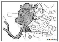
5. Rotate the spiral cable slightly so the locating pin (2) is positioned at the top.

• Locating hole (1) • Alignment arrows (B) 6. Remove the screws (A), then remove spiral cable from the steering column.

CAUTION: Do not turn the spiral cable quickly or beyond the limit number of turns (approximately 2.0 turns from the neutral position), this may cause the cable to snap.

7. Remove the steering angle sensor. Refer to BRC-242, "Removal and Installation".
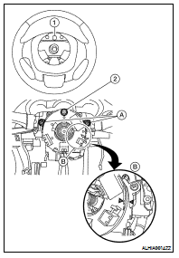
INSTALLATION

1. Set the spiral cable neutral position.

1. Slowly turn the spiral cable clockwise to the end position.

2. Next, turn it counterclockwise (about 2.0 turns) then stop turning at the point when the alignment arrows (B) are directly across from each other.

3. Rotate the spiral cable slightly so the locating pin (2) is positioned at the top.

NOTE: A service part is installed in the neutral position with a stopper clip in place and should not be adjusted after the stopper clip is removed.

2. Install the spiral cable in the reverse order of removal.

3. Align the locating hole (1) at the top of the steering wheel with the locating pin of spiral cable during installation.

CAUTION: • The spiral cable may snap by steering operation if the cable is installed in an improper position.

• Do not turn the spiral cable quickly or beyond the limit number of turns. (This can cause the cable to snap.) • After the work is completed, make sure no system malfunction is detected by air bag warning lamp.

• In case a malfunction is detected by the air bag warning lamp, reset with the self-diagnosis function and delete the memory with CONSULT−III.

• If a malfunction is still detected after the above operation, perform self-diagnosis to repair malfunctions.

Refer to SRC-12, "SRS Operation Check".

Driver air bag module

Exploded View 1. Steering switch connector 2. Steering switch ground connector 3. Steering switches 4. Driver air bag module 5. Driver air bag module connectors 6. Side lid (RH/LH) A. Steerin ...

Front passenger air bag module

Removal and Installation REMOVAL CAUTION: • Before servicing, turn ignition switch OFF, disconnect both battery terminals and wait at least three minutes. • Do not use air tools or electr ...