Nissan Altima (L32) 2007-2012 Service Manual: U1000 can comm circuit
Description
CAN (Controller Area Network) is a serial communication line for real time
applications. It is an on-vehicle multiplex
communication line with high data communication speed and excellent error
detection ability. Modern
vehicle is equipped with many electronic control unit, and each control unit
shares information and links with
other control units during operation (not independent). In CAN communication,
control units are connected
with 2 communication lines (CAN-H line, CAN-L line) allowing a high rate of
information transmission with less
wiring. Each control unit transmits/receives data but selectively reads required
data only.
CAN Communication Signal Chart, refer to LAN-25, "CAN Communication Signal
Chart"
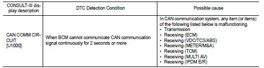
DTC Logic
DTC DETECTION LOGIC
Diagnosis Procedure
1.PERFORM SELF DIAGNOSTIC
Turn ignition switch ON and wait for 2 second or more.
2. Check “Self Diagnostic Result”.
Is “CAN COMM CIRCUIT” displayed?
YES >> Refer to LAN-8, "CAN Communication Control Circuit".
 Component diagnosis
 U1010 control unit (can)