Nissan Altima (L32) 2007-2012 Service Manual: U1000 can comm circuit
Description
Refer to LAN-7, "System Description".
DTC Logic
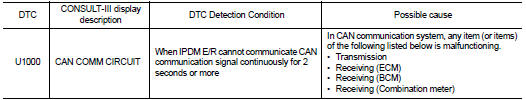
DTC DETECTION LOGIC
DTC CONFIRMATION PROCEDURE
Diagnosis Procedure
1. PERFORM SELF DIAGNOSTIC
1. Turn ignition switch ON and wait for 2 second or more.
2. Check “Self Diagnostic Result” of IPDM E/R.
Is “CAN COMM CIRCUIT” displayed?
YES >> Refer to PCS-20, "DTC Logic".
NO >> Refer to GI-42, "Intermittent Incident".
Description
• IPDM E/R operates the ignition relay when it receives an ignition switch ON
signal from BCM via CAN communication.
• Turn the ignition relay OFF by pressing the push-button ig ...
Other materials: Intelligent Around View Monitor
system limitations
WARNING
Listed below are the system limitations
for Intelligent Around View Monitor.
Failure to operate the vehicle in accordance
with these system limitations
could result in serious injury or death.
Do not use the Intelligent Around
View Monitor with the outside mirrors
in the stored positio ...
Intelligent Driver Alertness system
operation
For vehicles with the 7 inch (18 cm)
display
For vehicles with the 5 inch (13 cm)
display
If the system detects driver fatigue or that
driver attention is decreasing, the message
"Take a break?" appears in the vehicle
information display and a chime sounds
when the vehicle is driven at speeds abov ...
Oil control system (if so equipped)
The oil control system can be accessed in
the Maintenance portion of the vehicle information
display settings.
Engine oil information informs the distance
to oil change. Never exceed one year or
7,500 miles (12000 km) between oil change
intervals for the 2.0L 4 cylinder (KR20DDET
engine model) or 1 ...
 Component diagnosis
 B2098 ignition relay on stuck