Nissan Altima (L32) 2007-2012 Service Manual: Disassembly and assembly
CYLINDER BLOCK
Disassembly and Assembly
1. Drive plate reinforcement (CVT)
2. Drive plate (CVT), Flywheel (M/T)
3. Rear oil seal retainer
4. Knock sensor upper main bearing
5. Cylinder block
6. Thrust bearing (upper)
7. Main bearing (upper)
8. Crankshaft
9. Crankshaft key
10. Thrust bearing (lower)
11. Main bearing (lower)
12. Main bearing cap
13. Main bearing cap bolt
14. Main bearing beam
15. Baffle plate
16. Connecting rod bolt
17. Connecting rod bearing cap
18. Connecting rod bearing
19. Connecting rod
20. Snap ring
21. Piston pin
22. Piston
23. Oil ring
24. Second ring
25. Top ring
26. Pilot converter (CVT), Pilot bushing (MT)
27. Oil jet
A. Crankshaft side
B. Chamfered
C. Follow installation procedure
CAUTION: • Apply new engine oil to parts as marked in illustrations before installation.
• Place removed parts such as bearings and bearing caps in their proper order and direction.
• When installing the connecting rod nuts, and main bearing cap bolts, apply new engine oil to the threads and mating surfaces • Do not allow any magnetic materials to contact the signal plate teeth on the drive plate.
DISASSEMBLY
1. Remove the engine assembly. Refer to EM-202.
2. Install the engine on the engine stand.
3. Remove the knock sensor.
CAUTION: Carefully handle sensor avoiding shocking it.
4. Drain the engine of all coolant and oil.
5. Remove the oil pan. Refer to EM-139, "Removal and Installation".
6. Remove the timing chain. Refer to EM-163, "Removal".
7. Remove the cylinder head. Refer to EM-191, "Removal and Installation".
8. Remove drive plate or flywheel. Fix crankshaft with Tool, and remove bolts.
Tool number : KV10117700 (J-44716)
• Loosen bolts in diagonal order.
CAUTION: • Do not disassemble drive plate.
• Never place the drive plate with signal plate facing down.
• When handling signal plate, take care not to damage or scratch it.
• Handle signal plate in a manner that prevents it from becoming magnetized.
9. Remove pilot bushing (M/T) or converter (CVT) using Tool.
Tool number : ST16610001 (J-23907)
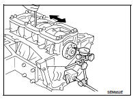
10. Cut away liquid gasket and remove rear oil seal retainer using Tool. Refer to EM-111, "Precaution for Liquid Gasket".
Tool number : KV10111100 (J-37228)
CAUTION: • Be careful not to damage mounting surface.
• If rear oil seal retainer is removed, replace it with a new one.
NOTE: Rear oil seal and retainer form a single part and are handled as an assembly.
11. Remove the piston and connecting rod assemblies.
a. Position the crankshaft pin corresponding to the connecting rod to be removed onto the bottom dead center.
b. Remove the connecting rod cap.
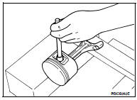
c. Using a hammer handle or similar tool, push the piston and connecting rod assembly out to the cylinder head side.
• Before removing the piston and connecting rod assembly, check the connecting rod side clearance. Refer to EM-234, "Cylinder Block".
12. Remove the connecting rod bearings.
CAUTION: • When removing the connecting rod side bearings, note the installation position. Keep them in the correct order.
13. Remove the piston rings from the piston.
• Use a piston ring expander.
CAUTION: • When removing the piston rings, be careful not to damage the piston. Do not expand the rings excessively.
• Be careful to mark the rings if they are to be reused so they are installed in their original position.
• Before removing the piston rings, check the piston ring side clearance.
Refer to EM-216, "Inspection".
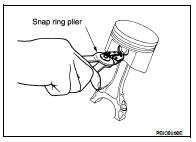
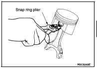
14. Remove the piston from the connecting rod as follows.
a. Using a snap ring pliers, remove the snap ring.
CAUTION: Do not reuse snap rings, always replace with new ones.
b. Heat the pistons to 60° - 70°C (140° - 158°F).
c. Push out the piston pin with a suitable tool, with an outer diameter approximately 20 mm (0.8 in).
15. Remove the rear oil seal retainer from the cylinder block.
• Insert a screwdriver or similar tool between the rear end of the crankshaft counter weight and rear oil seal retainer, and separate the liquid gasket to remove.
CAUTION: Be careful not to damage the mating surface.
NOTE: When replacing the rear oil seal during on-vehicle service, it is necessary to remove the oil pan. Refer to EM-139, "Removal and Installation".
16. Remove the baffle plate from the main bearing beam.
17. Loosen the bolts in the numerical order as shown and remove the main bearing beam, bearing caps and crankshaft.
• Before loosening the main bearing cap bolts, measure the crankshaft side clearance.
Refer to EM-216, "Inspection".
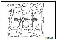
18. Remove the oil jets and dowel pins.
19. Remove the main bearings and thrust bearings from the cylinder block and main bearing caps.
• When removing them, note the direction and position. Keep them in the correct order for installation.
1. Blow out the coolant and oil passages and cylinder bore to remove any foreign materials.
WARNING: Use goggles to protect your eyes.
2. Apply liquid gasket and install each plug into the cylinder block.
• Use Genuine Silicone RTV Sealant or equivalent. Refer to GI-15, "Recommended Chemical Products and Sealants".
3. Install the oil jets.
• Insert the oil jet dowel pin into the cylinder block dowel pin hole, and tighten the bolts.
4. Install the main bearings and the thrust bearings.
a. Remove dust, dirt, and oil on the bearing mating surfaces of the cylinder block and the main bearing cap.
b. Install the thrust bearings to both sides of the No. 3 journal housing on the cylinder block and the main bearing cap.
• Install the thrust bearings with the oil groove facing the crankshaft arm (outside).
• Install bearing with a projection on one end on cylinder block and bearing with a projection at center on cap. Align each projection with mating notch.
5. Set the upper main bearings in their proper positions on the cylinder block.
• Confirm the correct main bearings are used. Refer to EM-216, "Inspection".
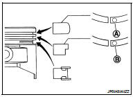
6. Instructions for the re-use of the main bearing cap bolts.
• A plastic zone tightening method is used for tightening the main bearing cap bolts. Measure d1 and d2 as shown.
• For d2, select the minimum diameter in the measuring area.
• If the difference between d1 and d2 exceeds the limit, replace the bolts for assembly.
Limit (d1 - d2) : 0.11 mm (0.0043 in)
7. After installing the crankshaft, lower main bearings, main bearing caps, main bearing beam, and bearing cap bolts. Tighten the bearing cap bolts in the numerical order as shown.
a. Make sure that the front marks on the main bearing beam faces the front of the engine.
b. Prior to tightening all the bearing cap bolts, place the bearing beam in its proper position by shifting the crankshaft in the axial position.
c. After tightening the bearing cap bolts, make sure the crankshaft turns smoothly.
d. Lubricate the threads and seat surfaces of the bolts with new engine oil.
e. Tighten the bolts in two stages:
CAUTION: Measure the tightening angle in stage 2 using Tool. Do not measure visually.
8. Measure crankshaft end play.
• If beyond the limit, replace the bearing with a new one.
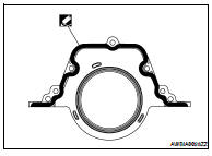
9. Install the rear oil seal retainer.
• Apply sealant to rear oil seal retainer as shown.
Use Genuine Silicone RTV Sealant, or equivalent. Refer to GI-15, "Recommended Chemical Products and Sealants".
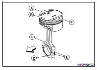
10. Install the piston to the connecting rod.
a. Using suitable snap ring pliers, install the snap ring fully into the pin-groove of the piston rear side.
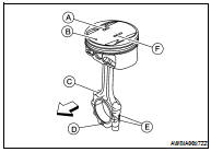
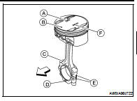
• Piston front mark (A) • Oil hole (B) • Connecting rod front mark (C) • Cylinder No. (D)
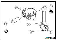
b. Install the piston to the connecting rod.
• Heat the piston until the piston pin can be pushed in by hand without excess force [approx. 60° - 70°C (140° to 158°F)].
From the front to the rear, insert the piston pin into the piston and through the connecting rod.
• Assemble so that the piston front mark (B) on the crown and the oil hole (C), connecting rod front mark (D) and Cylinder No.
(E) on the are positioned as shown.

- Piston grade number (A)
- Pin grade number (F)
c. Install the snap ring into the front of the piston pin-groove.
• After installing, check that the connecting rod pivots smoothly on the pin.
CAUTION: Do not reuse snap rings, always replace with new ones.
11. Using a piston ring expander, install the piston rings.
CAUTION: • Be careful not to damage the piston.
• When the piston rings are not replaced, remount the rings in their original positions.
• When replacing the piston rings, those without stamped surface (A) can be mounted either side up.
• Install the second ring with the stamped surface (B) facing upward. If the ring is not stamped it can face in either direction.
• Position each ring with the gap as shown, referring to the piston front mark.
12. Install the connecting rod bearings to the connecting rod and the connecting rod cap.
• When installing the connecting rod bearings, apply engine oil to the bearing surface (crankshaft side). Do not apply oil to the back surface (connecting rod and cap side), but thoroughly clean it.
• When installing, align the connecting rod bearing protrusion with the notch of the connecting rod to install.
• Check that the oil holes on the connecting rod and on the corresponding bearing are aligned.
13. Install the piston and connecting rod assembly into the corresponding cylinder.
• Position the crankshaft pin corresponding to the connecting rod to be installed onto the bottom dead center.
• Apply engine oil sufficiently to the cylinder bore, piston, and crankshaft pin.
• Match the cylinder position with the cylinder No. (B) on the connecting rod to install.
• Install the piston with the piston front mark (A) on the crown facing the front of the engine ( ), using a suitable tool.
- Oil hole (C)
CAUTION: Be careful not to damage the crankshaft pin and cylinder wall, resulting from an interference of the connecting rod big end.
14. Install the connecting rod cap.
• Match the stamped cylinder number marks on the connecting rod with those on the cylinder cap for installation.
• Install the piston connecting rod assembly and cap so that the front mark on the cap and piston are facing the front of the engine.
• Lubricate the threads and seat surfaces with new engine oil.
15. Check the connecting rod cap bolts before reusing, then install in their original position in the connecting rod. The bolts should screw in smoothly by hand.
• Measure the outer diameter of the connecting rod cap bolt as shown.
16. Tighten the connecting rod nuts in two stages using Tool:
CAUTION: Always use either an angle wrench or protractor. Avoid tightening based on visual check alone.
Tool number : KV10112100 (BT-8653-A)
• Apply engine oil to the threads and seats of the connecting rod bolts and nuts.
• After tightening the nuts, make sure that the crankshaft rotates smoothly.
• Check the connecting rod side clearance. If beyond the limit, replace the connecting rod and/or crankshaft.
17. Install the baffle plate to the main bearing beam.
18. Install the knock sensor.
• Make sure that there is no foreign material on the cylinder block mating surface and the back surface of the knock sensor.
• Install the knock sensor with the connector facing the rear of the engine.
• Do not tighten the bolts while holding the connector.
• Make sure that the knock sensor does not interfere with other parts.
CAUTION: If any impact by dropping occurs to the knock sensor, replace it with new one.
19. Install the pilot bushing (M/T) or converter (CVT) as shown.
20. Install the flywheel (M/T), if equipped.
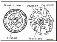
• When installing flywheel to crankshaft, be sure to correctly align crankshaft side dowel pin and flywheel side dowel pin hole.
21. Install the drive plate (CVT), if equipped.
• Install the drive plate and reinforce plate in the direction as shown.
• Align dowel pins of crankshaft rear and drive plate with pin holes of each part.
• Secure the crankshaft using a ring gear stopper.
• Tighten the drive plate bolts in one or two steps.
22. Install the cylinder head. Refer to EM-191, "Removal and Installation".
23. Install the timing chain. Refer to EM-166, "Installation".
24. Install the oil pan. Refer to EM-139, "Removal and Installation".
25. Remove the engine from the stand and install the engine assembly into the vehicle. Refer to EM-202, "Removal and Installation".
26. Assembly of the remaining parts is in the reverse order of disassembly.
27. Fill the engine with the specified oil and coolant. Refer to MA-12, "Engine Oil Recommendation" and MA- 12, "Fluids and Lubricants".
CAUTION: Wait at least 30 minutes for the sealant to set-up before filling the engine with fluids and running it.
Inspection
PISTON AND PISTON PIN CLEARANCE
Inner Diameter of Piston Pin Hole
• Measure the inner diameter of piston pin hole (dp).
Outer Diameter of Piston Pin
• Measure outer diameter of piston pin (Dp).

• Piston Grade No. (A) • Piston front mark (B) • Oil hole (C) • Connecting rod front mark (D) • Cylinder No. (E) • Pin Grade No. (F)
Piston and Piston Pin Interference Fit
Standard Interference Fit = (Dp) – (dp)
Standard : 0.002 – 0.010 mm (0.0001 – 0.0004 in)
• If clearance is exceeds specification, replace either or both of piston/piston pin assembly and connecting rod assembly with reference to specification of each part.
PISTON RING SIDE CLEARANCE
• Measure side clearance of piston ring and piston ring groove with feeler gauge.
• If out of specification, replace piston ring assembly. If clearance exceeds maximum limit with new rings, replace piston
PISTON RING END GAP
• Insert piston ring until it is in the middle of the cylinder bore and measure the end gap.
• If out of specification, replace piston ring.
CONNECTING ROD BEND AND TORSION
• If it exceeds the limit, replace connecting rod assembly.
CONNECTING ROD BEARING HOUSING DIAMETER (BIG END)
• Install the connecting rod cap without the connecting rod bearing installed. After tightening the connecting rod nut to the specified torque, measure the connecting rod bearing housing big end inner diameter using an inside micrometer.
Standard : 55.000 - 55.013 mm (2.1654 - 2.1659 in)
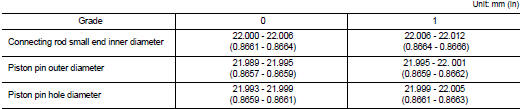
CONNECTING ROD BUSHING OIL CLEARANCE (SMALL END)
Inner Diameter of Connecting Rod (Small End)
• Measure inner diameter of piston pin bushing.
Outer Diameter of Piston Pin
• Measure outer diameter of piston pin.
Connecting Rod Bushing Oil Clearance (Small End) (Connecting rod small end oil clearance) = (Inner diameter of connecting rod small end) – (Outer diameter of piston pin)
• If the measured value exceeds the standard, replace the connecting rod assembly and/or piston and piston pin assembly.
• If replacing the piston and piston pin assembly, use the Table for Selective Fitting for Piston to select the piston corresponding to the applicable bore grade of the cylinder block to be used. Follow the "PISTON-TO-CYLINDER BORE CLEARANCE" procedure.
Factory installed parts grading:

• Piston Grade No. (A) • Piston front mark (B) • Oil hole (C) • Connecting rod front mark (D) • Cylinder No. (E) • Pin Grade No. (F)
Service parts apply only to grade 0.
CYLINDER BLOCK DISTORTION
• Using a scraper, remove any old gasket material on the cylinder block surface, and remove any oil, scale, carbon, or other contamination.
CAUTION: Be careful not to allow gasket flakes to enter the oil or coolant passages.
• Measure the distortion on the block upper face at different points in six directions.
Distortion limit : 0.10 mm (0.0039 in)
• If out of specification, resurface the cylinder block. The allowable amount of resurfacing is dependent on the amount of any cylinder head resurfacing. The resurfacing limit is [amount of cylinder head resurfacing] + [amount of cylinder head resurfacing] = 0.2 mm (0.008 in).
INNER DIAMETER OF MAIN BEARING HOUSING
• Install the main bearing caps with the main bearings removed, and tighten the bolts to the specified torque.
• Using a bore gauge, measure the inner diameter of the main bearing housing (A).
Standard : 63.993 - 64.017 mm (2.5194 - 2.5203 in)
• If out of the standard, replace the cylinder block and main bearing caps as an assembly.
NOTE: These components cannot be replaced as a single unit, because they were processed together.
PISTON-TO-CYLINDER BORE CLEARANCE
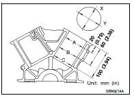
1. Using a bore gauge, measure cylinder bore for wear, out-of-round and taper at (A), (B) and (C). The X axis is in the longitudinal direction of the engine.
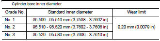
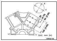
If it exceeds the limit, rebore all cylinders. Replace cylinder block if necessary.
2. Check for scratches and seizure. If seizure is found, hone it.
• If both cylinder block and piston are replaced with new ones, select piston of the same grade number punched on cylinder block rear position. These numbers are punched in either Arabic or Roman numerals.
3. Measure piston skirt diameter.
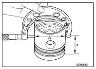
4. Check that piston-to-bore clearance is within specification.

• The piston-to-bore clearance is measured at the (B) level in the cylinder as shown.
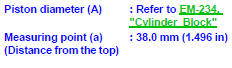
5. Cylinder bore size is determined by adding piston-to-bore clearance to piston diameter (A).
6. Install main bearing caps, and tighten to the specified torque. Otherwise, cylinder bores may be distorted after boring.
7. Cut cylinder bores.
• When any cylinder needs boring, all other cylinders must also be bored.
• Do not cut too much out of cylinder bore at a time. Cut only 0.05 mm (0.0020 in) or so in diameter at a time.
8. Hone cylinders to obtain specified piston-to-bore clearance.
9. Measure finished cylinder bore for out-of-round and taper.
• Measurement should be done after cylinder bore cools down.
CRANKSHAFT
1. Check the crankshaft main and pin journals for scoring, wear, or cracks.
2. Measure the journals for taper and out-of-round.
3. Measure crankshaft runout.
a. Place a V-block on a precise flat table to support the journals on the both ends of the crankshaft.
b. Place a dial gauge straight up on the No. 3 journal.
c. While rotating the crankshaft, read the movement of the pointer on the dial gauge.

BEARING CLEARANCE
• Use either of the following two methods, however method (A) gives more reliable results and so is the preferred method.
Method A (Using Bore Gauge and Micrometer) Main Bearing
1. Set the main bearings in their proper positions on the cylinder block and the main bearing cap.
2. Install the main bearing caps and bearing beam to the cylinder block. Tighten all bolts in the numerical order as specified. Refer to EM-206, "Disassembly and Assembly".
3. Measure the inner diameters (A) of each main bearing as shown.
4. Measure the outer diameters (Dm) of each crankshaft main journal as shown.
5. Calculate the main bearing clearance.
Main bearing clearance = (A) - (Dm)
• If it exceeds the limit, replace the bearing.
• If clearance cannot be adjusted using any standard bearing grade, grind crankshaft journal and use an undersized bearing.
• When grinding the crankshaft journal, confirm that the (L) dimension in the fillet role is more than the specified limit.
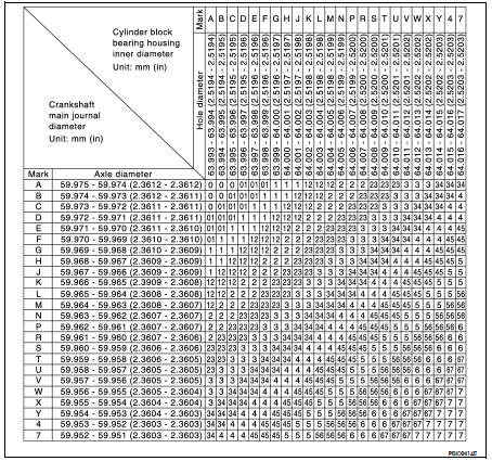
6. If the crankshaft or the cylinder block is replaced with a new one, select thickness of the main bearings as follows:
a. The grade number of each cylinder block main journal is punched on the respective cylinder block. These numbers are punched in either Arabic or Roman numerals. If measured diameter is out of the grade punched, decide suitable grade from available main bearings.
b. The grade number of each crankshaft main journal is punched on the crankshaft end. These numbers are punched in either Arabic or Roman numerals. If measured diameter is out of grade punched, decide the suitable grade from available main bearings.
c. Select the main bearing suitable thickness according to the following table:
Connecting Rod Bearing (Big End)
1. Install the connecting rod bearing to the connecting rod and cap.
2. Install the connecting rod cap to the connecting rod. Tighten to specification. Refer to EM-206, "Disassembly and Assembly".
3. Measure the inner diameter (C) of each connecting rod (big end) as shown.
4. Measure the outer diameter (Dp) of each crankshaft pin journal.
5. Calculate the connecting rod bearing clearance.
Connecting rod bearing clearance = (C) - (Dp)
6. If the calculated clearance exceeds the specified limit, replace the bearings.
7. If the clearance cannot be adjusted within the standard of any bearing, grind the crankshaft journal and use undersized bearings.
8. If the crankshaft is replaced with a new one, select the connecting rod bearings according to the following table:
Connecting Rod Bearing Grade Number (Identification Color)
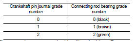
These numbers are punched in either Arabic or Roman numerals.
Method B (Using Plastigage)
• Remove oil and dust on the crankshaft pin and the surfaces of each bearing completely.
• Cut a Plastigage slightly shorter than the bearing width, and place it in crankshaft axial direction, avoiding oil holes.
• Install the connecting rod bearings to the connecting rod cap, and tighten the connecting rod nuts to the specified torque.
CAUTION: Never rotate the crankshaft.
• Remove the connecting rod cap and bearings, and using the scale on the Plastigage bag, measure the Plastigage width.
NOTE: The procedure when the measured value exceeds the repair limit is same as that described in "Method A (Using Bore Gauge and Micrometer)".
DRIVE PLATE RUNOUT (CVT)
Runout (Total Indicator Reading):

CAUTION: • The signal plate is built into the drive assembly. Be careful not to damage the signal plate, particularly the teeth.
• Check the drive plate and signal plate for deformation or cracks.
• Keep any magnetized objects away from the signal plate, particularly the teeth.
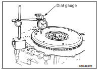
FLYWHEEL RUNOUT (M/T)
NOTE: • This inspection is for double mass flywheel only.
• Do not disassemble the double mass flywheel.
Flywheel Deflection
• Measure the deflection of the flywheel contact surface to the clutch with a dial gauge.
• Measure the runout at 210 mm (8.27 in) diameter.
Limit : 0.45 mm (0.0177 in) or less under no load
• When measured value exceeds the limit, replace the flywheel with a new one.
• Measure axial displacement at 250mm (9.84 in) diameter.
Movement Around in Rotation Direction
Check the movement amount with the following procedure: 1. Install a bolt to clutch cover mounting hole and place a torque wrench on the extended line of the flywheel center line.
• Tighten the bolt at a force of 9.8 N·m (1 kg-m, 87 in-lb) to keep it from loosening.
2. Put a mating mark on the circumference of the two flywheel masses without applying any load (measurement standard points).
3. Apply a force of 9.8 N·m (1 kg-m, 87 in-lb) in each direction, and mark the movement amount on the mass on the transaxle side.
4. Measure dimensions of movement amounts A and B on the circumference of the flywheel on the transaxle side.
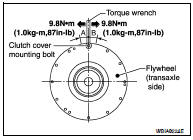
• When the measured value exceeds the standard, replace the flywheel.
OIL JET
• Check nozzle for deformation and damage.
• Blow compressed air from nozzle, and check for clogs.
• If it is not satisfied, replace oil jet.
OIL JET RELIEF VALVE
• Using a clean plastic stick, press check valve in oil jet relief valve.
Make sure that valve moves smoothly with proper reaction force.
• If it is not satisfied, replace oil jet relief valve.
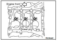
Dowel Pin Alignment
REMOVAL
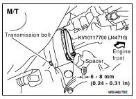
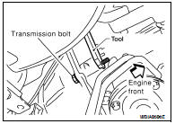
1. Use Tool to lock the flywheel (M/T) or drive plate (CVT) before removing the bolts.
Tool number : KV10117700 (J-48716)
CAUTION: Do not damage the ring gear teeth, or the signal plate teeth behind the ring gear, when setting Tool.
• CVT shown.
2. Remove the flywheel (M/T) or drive plate (CVT).
• Loosen the flywheel (M/T) or drive plate (CVT) bolts in a diagonal order.
CAUTION: • Do not disassemble the flywheel (M/T) or drive plate (CVT).
• Never place flywheel (M/T) or drive plate (CVT) with signal plate facing down.
• When handling the signal plate, take care not to damage or scratch it.
• Handle the signal plate in a manner that prevents it from becoming magnetized.
INSTALLATION (M/T)
Installation is in the reverse order of removal.
• When installing the flywheel to the crankshaft, use the triangle shaped match mark (A) as shown to correctly align the crankshaft side dowel pin to the flywheel side dowel pin hole.
• Tighten the flywheel bolts in a diagonal pattern in two steps. Refer to EM-206, "Disassembly and Assembly".
INSTALLATION (CVT)
Installation is in the reverse order of removal.
• When installing the drive plate to the crankshaft, use the triangle shaped match mark (A) as shown to correctly align the crankshaft side dowel pin to the drive plate side dowel pin hole.
• Install the drive plate and drive plate reinforcement plate in the direction as shown.
• Tighten the drive plate bolts in a diagonal pattern in two steps.
Refer to EM-206, "Disassembly and Assembly".
 Removal and installation
 Service data and specifications
(SDS)
Service data and specifications
(SDS)