Nissan Altima (L32) 2007-2012 Service Manual: Fuel injector and fuel tube
Removal and Installation
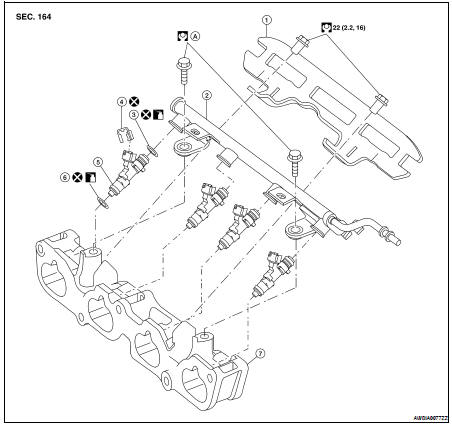
1. Fuel tube protector
2. Fuel tube
3. Upper O-ring (black)
4. Clip
5. Fuel injector
6. Lower O-ring (green)
7. Intake manifold adapter
A. Follow installation procedure
CAUTION: • Apply new engine oil before installing the parts, as shown above.
• Do not remove or disassemble parts unless instructed as shown.
REMOVAL
1. Remove engine room cover using power tool.
2. Release the fuel pressure. Refer to EC-550, "Inspection" (California), EC-1038, "Inspection" (Except California).
3. Remove the front air duct. Refer to EM-25, "Removal and Installation".
4. Disconnect the fuel hose quick connector at the fuel tube side.
CAUTION: • Prepare a container and cloth for catching any spilled fuel.
• This operation should be performed in a place that is free from any open flames.
• While hoses are disconnected seal their openings with vinyl bag or similar material to prevent foreign material from entering them.
5. Remove the intake manifold. Refer to EM-26.
6. Disconnect sub-harness for injector at engine front side, and remove it from bracket.
7. Loosen the bolts in the reverse order shown, then remove fuel tube and fuel injectors as an assembly.
8. Remove the fuel injectors from the fuel tube.
• Release the clip and remove the fuel injector.
• Pull fuel injector straight out of the fuel tube.
CAUTION: • Be careful not to damage the nozzle.
• Avoid any impact, such as dropping the fuel injector.
• Do not disassemble or adjust the fuel injector.
INSTALLATION
1. Install new O-rings on the fuel injector, the fuel side black O-ring and the nozzle side green O-ring.
CAUTION: • Upper and lower O-rings are different. Be careful not to confuse them.
- Fuel tube side: black O-ring
- Nozzle side: green O-ring
• Lubricate the O-rings lightly with new engine oil.
• Handle O-rings with bare hands only. Do not wear gloves.
• Do not clean O-rings with solvent.
• Make sure that O-ring and its mating part are free of foreign material.
• Be careful not to scratch O-rings during installation.
• Do not twist or stretch the O-ring. If the O-ring was stretched while it is attached, do not insert it into the fuel tube immediately.
2. Install the fuel injector (5) into the fuel tube (1) with the following procedure: • Do not reuse the clip (3), replace it with a new one.
• Insert the new clip (3) into the clip mounting groove (F) on fuel injector (5).
• Insert the clip (3) so that projection (E) of fuel injector (5) matches notch (C) of the clip (3).
• Fuel tube side: black O-ring (2) • Nozzle side: green O-ring (4) 3. Insert fuel injector (5) into fuel tube (1) with clip (3) attached.
• Insert it while matching it to the axial center.
• Insert fuel injector (5) so that projection (A) of fuel tube (1) matches notch (B) of the clip (3).
• Make sure that fuel tube flange (G) is securely fixed in flange fixing groove (D) on the clip (3).
• Make sure that installation is complete by checking that fuel injector (5) does not rotate or come off.
4. Install fuel tube assembly.
a. Insert the tip of each fuel injector (5) into intake manifold.
b. Tighten the bolts in two steps in the numerical order as shown.
Fuel tube assembly bolts
Step 1 : 10 N·m (1.0 kg-m, 7 ft-lb.) Step 2 : 22 N·m (2.2 kg-m, 16 ft-lb.)
CAUTION: After properly connecting fuel tube assembly to injector and fuel hose, check connection for fuel leakage.
5. Install the intake manifold. Refer to EM-26, "Removal and Installation".
6. Connect the fuel hose quick connector.
7. Installation of the remaining components is in the reverse order of removal.
INSPECTION AFTER INSTALLATION
Make sure there is no fuel leakage at connections as follows: 1. Apply fuel pressure to fuel lines by turning ignition switch ON (with engine stopped). Then check for fuel leaks at connections.
2. Start the engine and rev it up and check for fuel leaks at connections.
• Perform procedures for “Throttle Valve Closed Position Learning” after finishing repairs. Refer to EC-29, "THROTTLE VALVE CLOSED POSITION LEARNING : Description" (California), EC-565, "THROTTLE VALVE CLOSED POSITION LEARNING : Description" (Except California).
• If electric throttle control actuator is replaced, perform procedures for “Idle Air Volume Learning” after finishing repairs. Refer to EC-30, "IDLE AIR VOLUME LEARNING : Description" (California), EC-566, "IDLE AIR VOLUME LEARNING : Description" (Except California).
WARNING: Do not touch engine immediately after stopping as engine is extremely hot.
NOTE: Use mirrors for checking on connections out of the direct line of sight.
 Ignition coil
 Rocker cover