Nissan Altima (L32) 2007-2012 Service Manual: Mechanical system
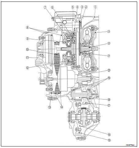
Cross-Sectional View
1. Converter housing
2. Driven sprocket
3. Chain
4. Reverse brake
5. Oil pump
Projekt?bersicht Website Erfahrungsberichte von Anlegern 6. Forward clutch
7. Planetary carrier
8. Primary pulley
9. Sun gear
10. Steel belt
11. Side cover
12. Internal gear
13. Parking gear
14. Secondary pulley
15. Final gear
16. Differential case
17. Idler gear
18. Reduction gear
19. Taper roller bearing
20. Output gear
21. Drive sprocket
22. Input shaft
23. Torque converter
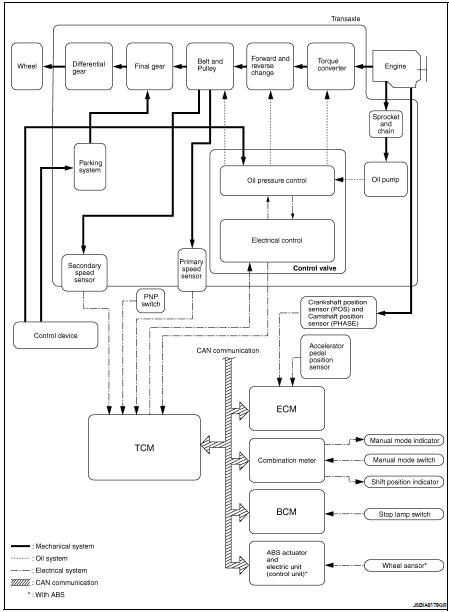
System Diagram
System Description
Transmits the power from the engine to the drive wheel.
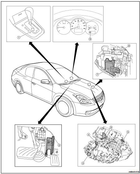
Component Parts Location - Coupe
1. Control device assembly
2. Accelerator pedal position sensor
3. CVT unit harness connector
4. Primary speed sensor
5. Secondary speed sensor
6. PNP switch
7. TCM
8. Battery
9. Shift position indicator
Manual mode indicator
Component Parts Location - Sedan
1. Control device assembly
2. Accelerator pedal position sensor
3. CVT unit harness connector
4. Primary speed sensor
5. Secondary speed sensor
6. PNP switch
7. TCM
8. Battery
9. Shift position indicator
Manual mode indicator
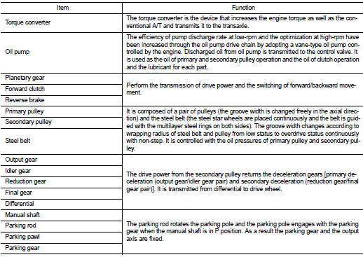
Component Description
System Diagram
Component Parts Location - Coupe
1. Control device assembly
2. Accelerator pedal position sensor
3. CVT unit harness connector
4. Primary speed sensor
5. Secondary speed senso ...
System Diagram
System Description
The hydraulic control mechanism consists of the oil pump directly driven by
the engine, the hydraulic control
valve that controls line pressure and transmiss ...
Other materials: Seats
WARNING
Do not ride in a moving vehicle when
the seatback is reclined. This can be
dangerous. The shoulder belt will not
be against your body. In an accident,
you could be thrown into it and receive
neck or other serious injuries.
You could also slide under the lap belt
and receive serious ...
Checking engine oil level
2.0L 4 cylinder (KR20DDET engine
model)
1. Park the vehicle on a level surface and
apply the parking brake.
2. Start the engine and let it idle until it
reaches operating temperature.
3. Turn off the engine. Wait more than 10
minutes for the oil to drain back into
the oil pan.
4. Remove the dips ...
ICC system limitations
WARNING
Listed below are the system limitations
for the ICC system. Failure to operate
the vehicle in accordance with these
system limitations could result in serious
injury or death:
The ICC system is primarily intended
for use on straight, dry, open roads
with light traffic. It is not advisabl ...

 CVT system
 Hydraulic control system