Nissan Altima (L32) 2007-2012 Service Manual: Speedometer
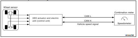
System Diagram
System Description
The ABS actuator and electric unit (control unit) provides a vehicle speed
signal to the combination meter via
CAN communication lines.
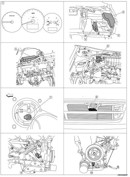
Component Parts Location
1. Combination meter M24
2. IPDM E/R E17, E18, E201, F10
3. ECM E10
4. TCM F16
5. BCM M17, M18, M19, M21 (view with
instrument panel removed)
6. ABS actuator and electric unit (control
unit) E26
7. Fuel level sensor unit and fuel pump
(fuel level sensor) B42 (view with rear
seat and inspection hole cover removed)
8. Ambient sensor E211 (view of front
bumper fascia)
9. Oil pressure switch F41 (QR25DE)
(view with engine removed)
10. Oil pressure switch F41 (VQ35DE)
(view with engine removed)
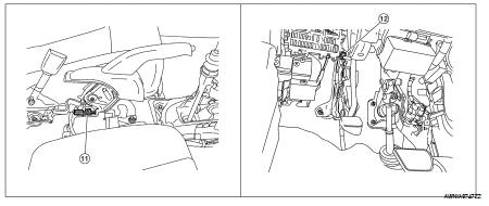
11. Parking brake switch M73
(Sedan with M/T and Coupe)
(view with center console removed)
12. Parking brake switch E35
(Sedan with CVT)
(view with instrument lower cover LH
removed)
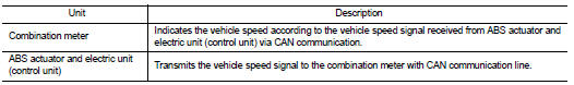
Component Description
System Diagram
System Description
COMBINATION METER
• Speedometer, odo/trip meter, tachometer, fuel gauge, engine coolant
temperature gauge and information
display are controlled by the unif ...
System Diagram
System Description
The tachometer indicates engine speed in revolutions per minute (rpm).
The ECM provides an engine speed signal to the combination meter via CAN
commu ...
Other materials: Seat belt extenders
If, because of body size or driving position, it
is not possible to properly fit the lap/
shoulder belt and fasten it, an extender
that is compatible with the installed seat
belts is available for purchase. The extender
adds approximately 8 in (200 mm)
of length and may be used for either the
driver ...
Child safety
WARNING
Do not allow children to play with the
seat belts. Most seating positions are
equipped with Automatic Locking Retractor
(ALR) mode seat belts. If the seat
belt becomes wrapped around a child’s
neck with the ALR mode activated, the
child can be seriously injured or killed if
the seat belt r ...
 Meter system
 Tachometer