Nissan Altima (L32) 2007-2012 Service Manual: Meter system
System Diagram
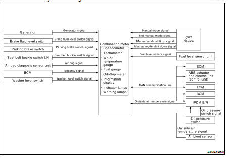
System Description
COMBINATION METER
• Speedometer, odo/trip meter, tachometer, fuel gauge, engine coolant temperature gauge and information display are controlled by the unified meter control unit, which is built into the combination meter.
• Warning and indicator lamps are controlled by the unified meter control unit and by components connected directly to the combination meter.
• Digital meter is adopted for odo/trip meter.* *The record of the odometer is kept even if the battery cable is disconnected. The record of the trip meter is erased when the battery cable is disconnected.
• Odo/trip meter and information display segments can be checked in diagnosis mode.
• Meter/gauge can be checked in diagnosis mode.
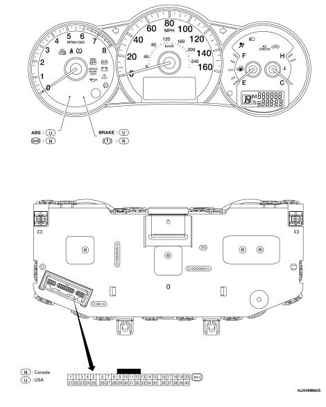
Arrangement of Combination Meter
Component Parts Location
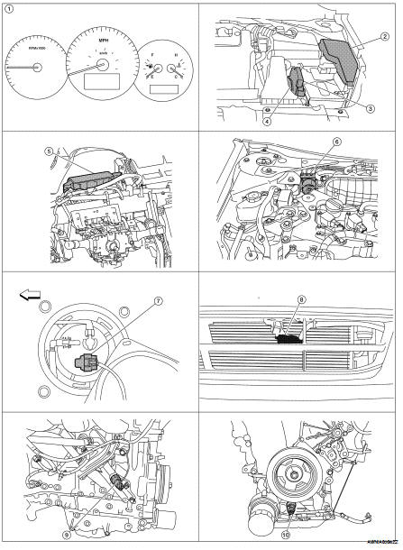
1. Combination meter M24
2. IPDM E/R E17, E18, E201, F10
3. ECM E10
4. TCM F16
5. BCM M17, M18, M19, M21 (view with instrument panel removed)
6. ABS actuator and electric unit (control unit) E26
7. Fuel level sensor unit and fuel pump (fuel level sensor) B42 (view with rear seat and inspection hole cover removed)
8. Ambient sensor E211 (view of front bumper fascia)
9. Oil pressure switch F41 (QR25DE) (view with engine removed)
10. Oil pressure switch F41 (VQ35DE) (view with engine removed)
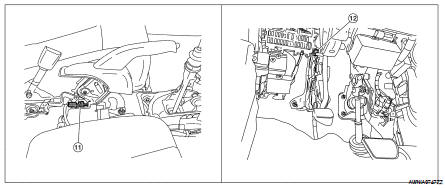
11. Parking brake switch M73 (Sedan with M/T and Coupe) (view with center console removed)
12. Parking brake switch E35 (Sedan with CVT) (view with instrument lower cover LH removed)
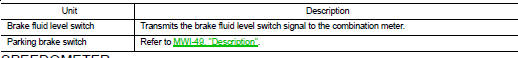
Component Description
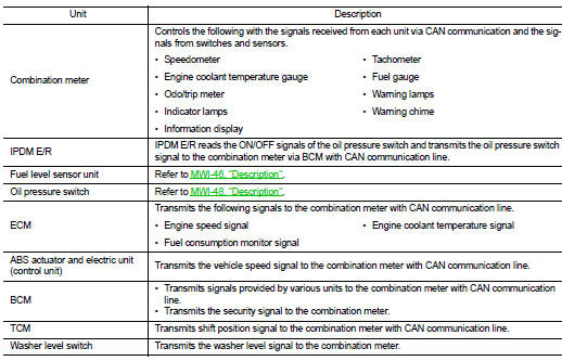
- Speedometer
- Tachometer
- Engine coolant temperature gauge
- Fuel gauge
- ODO/TRIP meter
- Shift position indicator
- Warning lamps/indicator lamps
- Information display
 Function diagnosis
 Speedometer