Nissan Altima (L32) 2007-2012 Service Manual: Stop lamp
Bulb Replacement
Removal
1. Remove rear combination lamp. Refer to EXL-257, "Removal and Installation".
2. Turn bulb socket counterclockwise to unlock and remove from combination lamp assembly.
3. Turn bulb counterclockwise to remove from bulb socket.
Installation
Installation is in the reverse order of removal.
Removal and Installation
HIGH MOUNTED STOP LAMP (with rear spoiler)
The high-mounted stop lamp uses an LED circuit board instead of a bulb. The LED circuit board is not serviceable and the high-mounted stop lamp must be replaced as an assembly. Refer to EXT-47, "Removal and Installation".
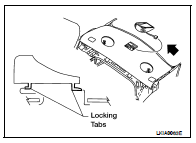
HIGH-MOUNTED STOP LAMP (with parcel shelf)
Removal
1. Slide the high-mounted stop lamp assembly rearward on the parcel shelf to give clearance to the front tabs.
2. Lift the front of the lamp assembly up and slide it forward to give clearance to the rear tabs.
3. Disconnect the high-mounted stop lamp connector and remove.
Installation
Installation is in the reverse order of removal.
REAR COMBINATION LAMP
Removal
1. Remove the trunk side finisher. Refer to INT-46, "Removal and Installation".
2. From inside the trunk, remove the rear combination lamp assembly nuts.
3. Disconnect the connectors and remove the rear combination lamp assembly.
Installation
Installation is in the reverse order of removal.
 Front fog lamp
 Back-up lamp