Nissan Altima (L32) 2007-2012 Service Manual: Fuel gauge
System Diagram
System Description
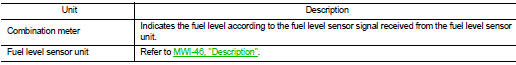
The fuel gauge indicates the approximate fuel level in the fuel tank.
The fuel gauge is regulated by the unified meter control unit and a variable
resistor signal supplied by the fuel
level sensor unit.
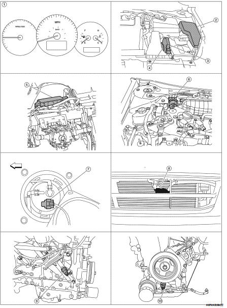
Component Parts Location
1. Combination meter M24
2. IPDM E/R E17, E18, E201, F10
3. ECM E10
4. TCM F16
5. BCM M17, M18, M19, M21 (view with
instrument panel removed)
6. ABS actuator and electric unit (control
unit) E26
7. Fuel level sensor unit and fuel pump
(fuel level sensor) B42 (view with rear
seat and inspection hole cover removed)
8. Ambient sensor E211 (view of front
bumper fascia)
9. Oil pressure switch F41 (QR25DE)
(view with engine removed)
10. Oil pressure switch F41 (VQ35DE)
(view with engine removed)
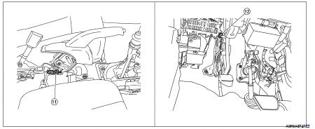
11. Parking brake switch M73
(Sedan with M/T and Coupe)
(view with center console removed)
12. Parking brake switch E35
(Sedan with CVT)
(view with instrument lower cover LH
removed)
Component Description
System Diagram
System Description
The engine coolant temperature gauge indicates the engine coolant
temperature.
The ECM provides an engine coolant temperature signal to the combination mete ...
System Diagram
System Description
The vehicle speed signal and the memory signals from the meter memory circuit
are processed by the combination
meter and the mileage is displayed.
HOW TO CHA ...
Other materials: Front manual seat adjustment
(if so equipped)
Your vehicle seats can be adjusted manually.
For additional information about adjusting
the seats, refer to the steps outlined
in this section.
WARNING
Before driving the vehicle, return the
seatback to an upright seating position
after manually releasing it. Also, make
sure the seat is locked in p ...
Supplemental air bag warning labels
Warning labels about the supplemental
front-impact air bag system are placed in
the vehicle as shown in the illustration.
WARNING
Do not use a rear-facing child restraint
on a seat protected by an air bag in
front of it. If the air bag deploys, it may
cause serious injury or death.
Supplemental air ...
Warning lights, indicator lights and audible
reminders
Warning/Indicator light (red)
Brake warning light
Charge warning light
Electronic parking brake
indicator
light (if so equipped)
Engine oil pressure warning
light
Master warning light
Seat belt warning light and
chime
Security indicator light
Supplemental air bag warning
light
Warning/Indic ...
 Engine coolant temperature gauge
 ODO/TRIP meter