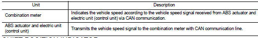
Nissan Altima (L32) 2007-2012 Service Manual: ODO/TRIP meter
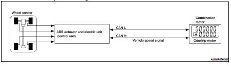
System Diagram
System Description
The vehicle speed signal and the memory signals from the meter memory circuit
are processed by the combination
meter and the mileage is displayed.
HOW TO CHANGE THE DISPLAY FOR ODO/TRIP METER
Refer to Owner's Manual for odo/trip meter operating instructions.
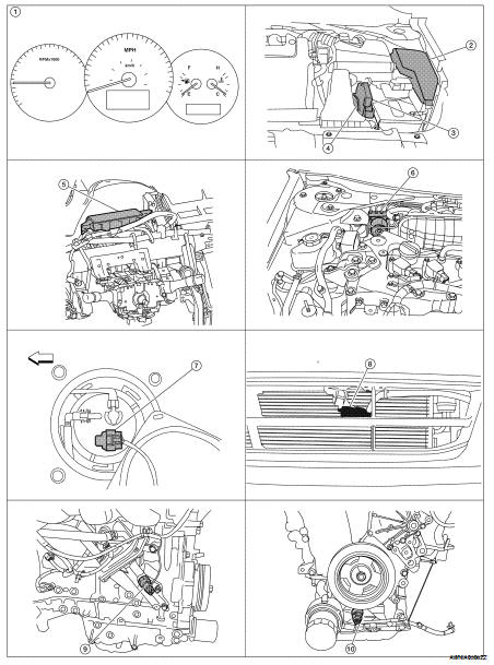
Component Parts Location
1. Combination meter M24
2. IPDM E/R E17, E18, E201, F10
3. ECM E10
4. TCM F16
5. BCM M17, M18, M19, M21 (view with
instrument panel removed)
6. ABS actuator and electric unit (control
unit) E26
7. Fuel level sensor unit and fuel pump
(fuel level sensor) B42 (view with rear
seat and inspection hole cover removed)
8. Ambient sensor E211 (view of front
bumper fascia)
9. Oil pressure switch F41 (QR25DE)
(view with engine removed)
10. Oil pressure switch F41 (VQ35DE)
(view with engine removed)
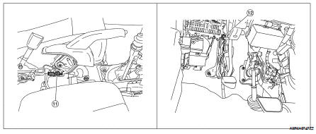
11. Parking brake switch M73
(Sedan with M/T and Coupe)
(view with center console removed)
11. Parking brake switch M73
(Sedan with M/T and Coupe)
(view with center console removed)
Component Description
System Diagram
System Description
The fuel gauge indicates the approximate fuel level in the fuel tank.
The fuel gauge is regulated by the unified meter control unit and a variable
resistor s ...
System Diagram
System Description
The TCM receives CVT indicator signals from the park/neutral position (PNP)
switch. The TCM then sends
CVT position indicator signals to the combination meter ...
Other materials: Heated steering wheel switch (if so equipped)
Push the heated steering wheel switch to
warm the steering wheel after the ignition
switch is placed in the ON position. The
indicator light will come on.
If the surface temperature of the steering
wheel is below 68ºF (20ºC), the system will
heat the steering wheel and cycle off and
on to mainta ...
Seat belt extenders
If, because of body size or driving position, it
is not possible to properly fit the lap/
shoulder belt and fasten it, an extender
that is compatible with the installed seat
belts is available for purchase. The extender
adds approximately 8 in (200 mm)
of length and may be used for either the
driver ...
Precautions on SRS
This SRS section contains important information
concerning the following systems:
Driver and front passenger supplemental
front-impact air bag (NISSAN Advanced
Air Bag System)
Front seat-mounted side-impact supplemental
air bag
Rear outboard seat-mounted side-impact
supplemental air bag
Roo ...
 Fuel gauge
 Shift position indicator