Nissan Altima manuals

Nissan Altima (L32) 2007-2012 Service Manual: Warning lamps/indicator lamps
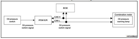
System Diagram

System Description

OIL PRESSURE WARNING LAMP

The oil pressure warning lamp is controlled by the IPDM E/R (intelligent power distribution module engine room).

Low oil pressure causes the oil pressure switch to provide a ground signal to the IPDM E/R. The IPDM E/R then signals the combination meter (unified meter control unit) via the CAN communication lines and ground is provided to the oil pressure warning lamp.

When power and ground are supplied, the oil pressure warning lamp illuminates.

 Component Parts Location

1. Combination meter M24

2. IPDM E/R E17, E18, E201, F10

3. ECM E10

4. TCM F16

5. BCM M17, M18, M19, M21 (view with instrument panel removed)

6. ABS actuator and electric unit (control unit) E26

7. Fuel level sensor unit and fuel pump (fuel level sensor) B42 (view with rear seat and inspection hole cover removed)

8. Ambient sensor E211 (view of front bumper fascia)

9. Oil pressure switch F41 (QR25DE) (view with engine removed)

10. Oil pressure switch F41 (VQ35DE) (view with engine removed)

11. Parking brake switch M73 (Sedan with M/T and Coupe) (view with center console removed)

12. Parking brake switch E35 (Sedan with CVT) (view with instrument lower cover LH removed)

Component Description

Shift position indicator
System Diagram System Description The TCM receives CVT indicator signals from the park/neutral position (PNP) switch. The TCM then sends CVT position indicator signals to the combination meter ...

Information display
System Diagram System Description FUNCTION The information display can indicate the following items. • Outside air temperature • Trip/fuel consumption readings • Intelligent Key operat ...

Other materials:

Front fog lamp
Aiming Adjustment The fog lamp is a semi-sealed beam type which uses a replaceable halogen bulb. Before performing aiming adjustment, make sure of the following. • Keep all tires inflated to correct pressure. • Place vehicle on level ground. • See that vehicle is unloaded (except ...

Diagnosis system (AV control unit)
Diagnosis Description DESCRIPTION • Diagnosis function consists of the self-diagnosis mode performed automatically and the CONFIRMATION/ ADJUSTMENT mode operated manually. • Self-diagnosis mode checks for connections between the units constituting this system, analyzes each individual ...

P0181 FTT Sensor
Description The fuel tank temperature sensor is used to detect the fuel temperature inside the fuel tank. The sensor modifies a voltage signal from the ECM. The modified signal returns to the ECM as the fuel temperature input. The sensor uses a thermistor which is sensitive to the change in te ...