Nissan Altima manuals

Nissan Altima (L32) 2007-2012 Service Manual: Shift position indicator
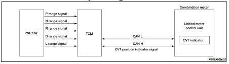
System Diagram

System Description

The TCM receives CVT indicator signals from the park/neutral position (PNP) switch. The TCM then sends CVT position indicator signals to the combination meter via CAN communication lines. The combination meter indicates the received shift position.

Component Parts Location

1. Combination meter M24

2. IPDM E/R E17, E18, E201, F10

3. ECM E10

4. TCM F16

5. BCM M17, M18, M19, M21 (view with instrument panel removed)

6. ABS actuator and electric unit (control unit) E26

7. Fuel level sensor unit and fuel pump (fuel level sensor) B42 (view with rear seat and inspection hole cover removed)

8. Ambient sensor E211 (view of front bumper fascia)

9. Oil pressure switch F41 (QR25DE) (view with engine removed)

10. Oil pressure switch F41 (VQ35DE) (view with engine removed)

11. Parking brake switch M73 (Sedan with M/T and Coupe) (view with center console removed)

12. Parking brake switch E35 (Sedan with CVT) (view with instrument lower cover LH removed)

Component Description

ODO/TRIP meter
System Diagram System Description The vehicle speed signal and the memory signals from the meter memory circuit are processed by the combination meter and the mileage is displayed. HOW TO CHA ...

Warning lamps/indicator lamps
System Diagram System Description OIL PRESSURE WARNING LAMP The oil pressure warning lamp is controlled by the IPDM E/R (intelligent power distribution module engine room). Low oil pressure ...

Other materials:

Spark plug
Removal and Installation 1. Ignition coil 2. Spark plug 3. Rocker cover REMOVAL 1. Remove the ignition coil. Refer to EM-35, "Removal and Installation". 2. Remove the spark plug with a suitable spark plug wrench. INSPECTION AFTER REMOVAL • Do not use a wir ...

Intelligent key system/engine start function symptoms
Symptom Table Engine cannot be started with all Intelligent Keys. CAUTION: • Follow Trouble Diagnosis Flowchart referring to “SEC-209, "Work Flow"”. Determine malfunctioning condition before performing this diagnosis. • Check that vehicle is under the condition shown in ...

P0137 HO2S2
Description The heated oxygen sensor 2, after three way catalyst (manifold), monitors the oxygen level in the exhaust gas on each bank. Even if switching characteristics of the air fuel ratio (A/F) sensor 1 are shifted, the air-fuel ratio is controlled to stoichiometric, by the signal from t ...